

Abstract
Microfluidic chips have been developed to generate droplets and microparticles with control over size, shape, and composition not possible using conventional methods. However, it has remained a challenge to scale-up production for practical applications due to the inherently limited throughput of micro-scale devices. To address this problem, we have developed a self-contained microchip that integrates many (N = 512) micro-scale droplet makers. This 3 × 3 cm2 PDMS microchip consists of a two-dimensional array of 32 × 16 flow-focusing droplet makers, a network of flow channels that connect them, and only two inputs and one output. The key innovation of this technology is the hybrid use of both soft-lithography and direct laser-micromachining. The microscale resolution of soft lithography is used to fabricate flow-focusing droplet makers that can produce small and precisely defined droplets. Deeply engraved (h ≈ 500 μm) laser-machined channels are utilized to supply each of the droplet makers with its oil phase, aqueous phase, and access to an output channel. The engraved channels' low hydrodynamic resistance ensures that each droplet maker is driven with the same flow rates for highly uniform droplet formation.To demonstrate the utility of this approach, water droplets (d ≈ 80 μm) were generated in hexadecane on both 8 × 1 and 32 × 16 geometries.
Introduction
Microfluidic chips that generate droplets and microparticles have been utilized for a wide variety of applications, including the generation of droplets for digital biological assays,1–5 the fabrication of functional microparticles,6–11 and the synthesis of nanoparticles.12–17 The small feature-size of microfluidics enables fine control over size, shape, and composition of droplets and microparticles, with extremely high levels of uniformity.18,19 However, the limited throughput of micro-scale devices, make these approaches unsuitable for many practical applications.19,20
One promising approach to increase the throughput of microfluidic-based approaches is to incorporate multiple droplet makers onto a single chip for parallel operation. For conventional single-layer microfluidics the number of inputs and outputs n scales with n ∝ N, the number of generators,19 (Fig. 1a) resulting in an impractically large number of connections to the outside world. By using a second layer of microfluidic channels to supply each generator, analogous to the architecture of an integrated circuit,21 large arrays can be packed onto a single chip with only a single set of inputs and outputs (n = 3 for single emulsions) (Fig. 1b). Previous work to integrate arrays of microfluidic droplet makers include the use of a machined metal fitting to feed a circular array of 256 PDMS molded droplet makers.20 Additionally, devices have been developed that use multiple layers of microfabricated channels coupled together with either drilled22 or punched holes.23,24 Because these previous approaches rely on macroscopically defined through-holes, there is a practical limit to the number of generators that can be integrated onto a single chip (N ∼ 100).20,23,24
Fig. 1.
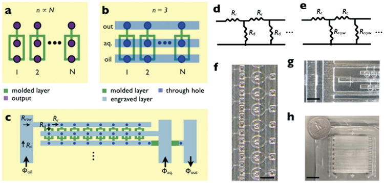
A hybrid soft-lithography/laser micromachined PDMS microchip for highly parallel droplet formation. a. For single-layer microfluidics, the topology of a droplet maker requires that the number of inputs/outputs n is proportional to the number of droplet makers n ∝ N. b. By adding a second layer of microfluidics, the number of inputs for an array of droplet makers is n = 3 regardless of N. The droplet makers are molded into PDMS using soft lithography (green) and the delivery lines (blue) and through-holes (purple) are fabricated using laser micromachining. c. The droplet makers are organized into a ladder geometry, where each row of droplets is supplied by a single oil Φoil, aqueous Φaq., and output line Φout. Each row is supplied by an arterial row-delivery line, in a ladder geometry. d. The flow resistance of the ladder geometry is modeled as a series of flow resistors, with the resistance of the droplet makers Rd and that of the rows Rr. e. For the supply of fluid to each row, we model a similar circuit with the resistance of the arterial channel Rc and the total resistance of each row Rrow. f. A micrograph of a row of droplet makers. The scale bar is 600 μm. g. A micrograph of the arterial supply line and underpass. The scale bar is 1.5 mm. h. A photograph of the chip. The scale bar is 20 mm.
To address this issue, we have developed a fully microfabricated, self-contained 3 × 3 cm2 PDMS microchip that consists of a two-dimensional array of 32 × 16 (512) flow-focusing droplet makers, an integrated network of channels to drive each droplet maker, and only two inputs and one output. To build this chip, we used both soft-lithography and laser micromachining. The microscale resolution of soft lithography was used to fabricate flow-focusing droplet makers with an aperture of 30 μm that can produce small and precisely defined droplets. Laser micromachining enabled larger feature sizes and higher aspect ratios to create deeply engraved channels (h ≈ 500 μm), which supply each of the droplet makers with its oil phase, aqueous phase, and access to an output channel. The engraved channels' low hydrodynamic resistance ensured that each droplet maker was uniformly driven to create homogenous droplets. To demonstrate the utility of this platform, d ≈ 80 μm water droplets were generated in hexadecane containing Span 80 (1.5% v/v) on both a single row 8 × 1 and a two dimensional array 32 × 16 (512) geometry.
Experimental design
To deliver fluid to each of the droplet makers, we used a ladder geometry with each maker connected to an oil, aqueous, and output line (Fig. 1b). The spine of the ladder is an engraved supply line and each rung of the ladder is a molded flow-focusing droplet maker. To ensure that each drop maker behaves identically, we designed the microchip such that the pressure drop along the supply channel Pr remains small compared to the pressure drop across the individual drop makers Pr ≪ Pd. To enforce this design condition, we adopted the following design rule,23
| (1) |
where Rr is the fluidic resistance along the delivery channel between each drop maker, Rd is the fluidic resistance of the individual droplet maker, and N is the number of droplet makers in the row (Fig. 1d). The row delivery lines and droplet makers consisted of rectangular microchannels, whose fluidic resistance R can be approximated25
| (2) |
where μ is the dynamic viscosity of the fluid and w, h, and l are the width, height, and length of the microchannel. The row delivery channel has a width wr = 0.6 mm, height hr = 0.55 mm, and length lr = 40 mm. The flow-focusing droplet maker was modeled as rectangular channels in series with wd = 50 μm, 30 μm, 50 μm, and ld = 1600 μm, 380 μm, 500 μm, hd = 30 μm for oil, water, and their mixture respectively. For this geometry, we calculated that we can satisfy the design condition eqn (1) for Nd < 360. This number could be increased further by either increasing the size of the row delivery channel or decreasing the size of the droplet makers. For our two dimensional array, we set the number of droplet makers per row Nd = 32. A micrograph of a row of droplet makers is shown in Fig. 1f.
To deliver fluid to each of the rows, we used a ladder geometry with each row connected to a single arterial supply line (Fig. 1c). The supply line is a rectangular channel with wd = 1.4 mm, hd = 0.55 mm, and ld = 40 mm. Because the resistance of the drop makers are much larger than that of the row delivery lines, we modeled the resistance from the arterial line through each row as Nd = 32 droplet makers in parallel Rrow ∼ Rd/Nd (Fig. 1e). We calculated that the design condition eqn (1) can be satisfied for Nr < 19 (for both the water and oil channels). This number could be increased further by either increasing the size of the arterial line or decreasing the size of the droplet makers. We set the number of rows per device Nr = 16. A micrograph of the ladder geometry that supplies each row is shown in Fig. 1g. A photograph of the 3 × 3 cm2 two dimensional array chip is shown in Fig. 1h next to a quarter dollar for scale.
Device fabrication
The fabrication strategy consisted of integrating three separate pieces: 1. a laser-engraved layer of PDMS that contains channels to deliver fluid to the droplet makers below (Fig. 2a). 2. An intermediate layer of spin-coated PDMS that is laser cut with through-holes to connect the engraved layer to the droplet makers (Fig. 2b). 3. A soft-lithography molded layer of PDMS that contains a two dimensional array of droplet makers (Fig. 2c). The three separate pieces were bonded together by stamping the pieces into spin-coated uncured PDMS,26 aligning the pieces together under a stereoscope with a custom alignment rig, and baking (Fig. 2d). All pieces were fabricated using poly(dimethylsiloxane) (PDMS) (KR Anderson Company, Sylgard/elastomer kit). The dimensions of the droplet makers and connecting channels are given in the Experimental Design section above. The laser cut through-holes are 270 × 270 μm2 for the oil, 180 × 180 μm2 for the aqueous phase, and 270 × 270 μm2 for the output. The complete mask design is included in ESI.†
Fig. 2.
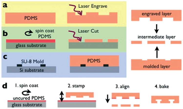
Fabrication strategy. The hybrid chip consists of three layers, a. A laser engraved layer, which includes the delivery microchannels. b. A laser cut intermediate layer that contains the through-holes that connect the laser engraved layer and the droplet makers. c. A soft-lithography molded layer that includes the droplet makers. Uncured and cured PDMS are shown in red and orange, respectively. d. The layers are combined together using a stamping and baking technique, in which 1. a thin layer of PDMS in spun coat onto a silicon wafer, 2. one of the pieces is stamped into the uncured PDMS, 3. two layers are aligned and bonded using a custom built rig under a stereoscope, and 4. the pieces are baked to cure the PDMS.
The laser engraved layer and the intermediate layer were machined using an infrared laser micromachining system (VLS3, VersaLaser). The molded layer was fabricated using standard single-layer SU-8 lithography (SU-8 2025, MicroChem) with 30 μm thick features.23 For the engraved layer, a 4 mm thick layer of PDMS was poured into a plastic petri dish and baked. This piece was then laser engraved using raster-based laser patterning, for a channel thickness h ≈ 500 μm. For the intermediate layer, a 200 μm thick layer of PDMS was spin coated (ws-650mz-23npp, Laurell) and then baked. This spin coated layer was then laser cut using vector-based laser patterning to make through holes. Both the engraved and the intermediate layer were cleaned in a solution of tergazyme detergent (Sigma-Aldrich) in deionized water for 10 minutes in a sonicator, followed by a 10 minute soak in deionized water, followed by nitrogen blow drying. Washing using a detergent instead of isopropanol avoided swelling of the PDMS, which allowed for better alignment of the layers. Prior to use, the microfluidic channels were coated with Aquapel (PPG Industries) to ensure that they were preferentially wet by the hexadecane oil.
Results
Single row device
The first prototype that we built consisted of a single row of 8 droplet makers (Fig. 3a). Extending from each droplet maker is a 3 mm long channel, such that the droplets could be consistently imaged and droplet size and uniformity characterized. The aqueous phase input was set to Φaq = 0.8 mL h−1 and the oil phase was set to Φoil = 3 mL h−1, using two syringe pumps (NE 500, New Era Pumping Systems). Droplet formation was observed on all eight drop makers using an upright microscope (Leica, DM4000B) (Fig. 3b). The rate of droplet formation for the array was calculated to be 4 × 10⁵ droplets per minute. The flow rates were chosen to facilitate characterization, by producing spatially separated droplets from each droplet maker. A video of droplet formation can be found the ESI.†
Fig. 3.
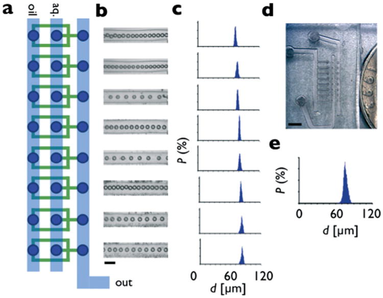
Characterization of a single row device. a. Eight flow focusing droplet makers are organized into a single row, with oil, aqueous, and output lines connected in a ladder geometry. b. Optical micrographs show uniform droplets are created by each droplet maker. The scale bar is 150 μm. c. Histograms of the diameter of the droplets from each individual droplet maker show an average diameter of d = 78.6 μm and an average CV of 2.1%. d. A photograph of the single row device. Scale bar: 1 mm. e. The histogram of the total output of the device shows a CV of 3.6%.
The droplet diameters were measured using image analysis software (ImageJ). The average diameter for the droplet makers was d = 78.6 μm and the coefficient of variation CV of the individual droplet makers was 2.1%. The CV from the total output of all eight droplet makers was 3.6% (Fig. 3e). The variations in drop size did not significantly increase or decrease as a function of position along the ladder geometry, demonstrating that the pressure drop on the supply line was not significant. A photograph of the droplet maker device used in these experiments is shown in Fig. 3d.
Two dimensional droplet array
Based on the design constraints outlined in the sections above, we designed and fabricated a two dimensional droplet array consisting of 32 rows, with each row consisting of 16 drop makers (Fig. 4a). Each of the 512, 30 μm aperture flow focusing drop makers (Fig. 4b) connect to a source of oil and aqueous phase as well as to an output path. The fluid delivery lines run across each row in a ladder geometry. On the edge of the array, each row is supplied by an arterial supply channel (Fig. 4d). An underpass geometry connects each of the rows to the arterial output line, allowing it to pass under the arterial lines that supply the oil and aqueous phase. The underpass brings the fluid from the engraved level down to the molded level, where it passes under the oil or aqueous supply line, and back to the engraved level to meet with the arterial output line, which runs along both edges of the chip (Fig. 4c).
Fig. 4.
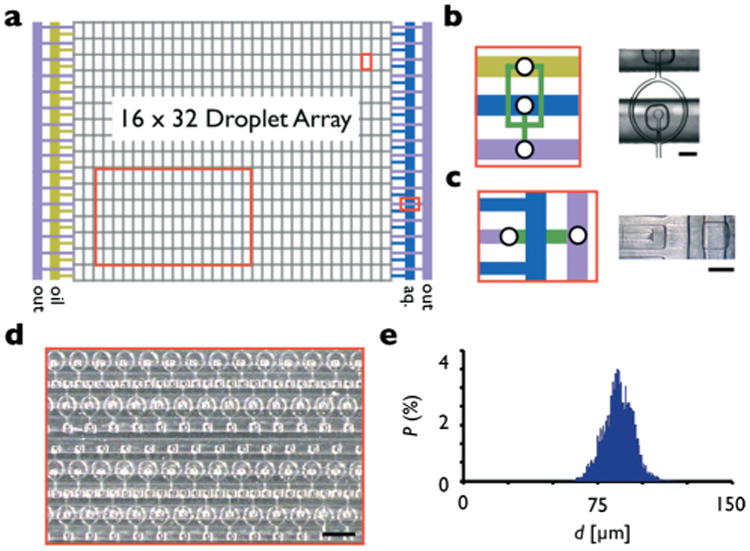
Two dimensional array. a. The array of droplet generators is organized into 16 rows, each row consisting of 32 droplet makers. The array is fed by a single aqueous (blue), oil (yellow), and output (purple) line. b. A schematic and stereoscope micrograph of the flow focusing droplet makers. The scale bar is 100 μm. c. A schematic and stereoscope micrograph of the underpass structure, which allows the output lines to pass under the oil line on the left edge and the aqueous line on the right edge of the array. The underpass sends the output from the engraved layer down to the molded layer (green), and then back to the engraved layer where it connects to an arterial line. Scale bar: 500 μm. d. A stereoscope micrograph of the droplet array. Scale bar: 3 mm. e. A histogram of the diameter of the droplets from the array of droplet makers show an average diameter of d = 86.1 μm and a CV of 9.0%.
We tested the two dimensional array of droplet makers using two syringe pumps, one for the oil and one for the aqueous input. The aqueous phase input was set to Φaq = 8 mL h−1 and the oil phase was set to Φoil = 20 mL h−1. We observed droplet formation on all five hundred and twelve drop makers using an upright microscope (Leica, DM4000B). We calculated the rate of droplet formation, 4 × 10⁶ droplets per minute. This rate was not limited by the device but by the syringe pumps and could be improved by switching to peristaltic pumps. A histogram was generated for the total output of the 512 droplet makers (Fig. 4e). The droplets had an average diameter of d = 86.1 μm and CV = 9.0%. We hypothesize that the variations in droplet size from droplet-maker to droplet-maker increased relative to the 8 droplet device, due to the increased area of the chip which exacerbated small misalignment. Alignment could be improved by using a material more rigid than PDMS (e.g. fused silica27).
Discussion
We have developed a novel technology for integrating many droplet makers onto a single PDMS chip. Our hybrid laser micromachined/soft lithography defined device uses the following elements to maximize the density of droplet makers, while maintaining droplet homogeneity: 1. deep, laser micromachined channels to deliver flow to each of the droplet makers with minimum variation in pressure, 2. fine-featured soft-lithography defined droplet makers to create small and uniform droplets. 3. Only two inputs and one output to enable simple use and integration. Furthermore, the all-PDMS construction of the device enables inexpensive manufacturing.
The device architecture developed in this paper can be extended to chips with more droplet makers than the 512 demonstrated in this paper. The main limitation to increasing the number of droplet makers is the design condition outlined in eqn (1). Due to this constraint, increases in the number of droplet makers N must be accompanied by a decrease in the flow resistance of the supply lines or an increase in the flow resistance of the droplet makers. By isotropically scaling the droplet makers from having an aperture size of 30 μm to 2 μm, the flow resistance of the drop maker Rd ∝ l/(wh3) would increase by a factor of ∼103. This scaling would allow for approximately 1000× more droplet makers N to be included for a given supply channel. However, to pack droplet makers this densely, the infrared laser micromachining used in this study, which has a resolution of ∼100 μm, would not be sufficient. We hypothesize that UV laser micromachining could be utilized, which can achieve ∼1 μm feature size.28 With such a device we estimate that on a 3 × 3 cm2 chip 2 × 10⁶ droplet makers can be fabricated (1000 × 2000), with a throughput of >10 × 109 droplets per minute. Additional opportunities for future development includes replacing the flow-focusing droplet makers with T-junctions29 which require less space per drop maker and can be packed more densely or the addition of droplet splitters to further increase droplet generation.31 Additionally, more complex droplets can be generated that require N > 2 inputs per device, such as Janus microparticles30 or multiple emulsions.23
Supplementary Material
Acknowledgments
This work is supported by the Department of Bioengineering, University of Pennsylvania, a pilot grant from the University of Pennsylvania Nano/Bio Interface Center-National Science Foundation DMR 08-32802, and a pilot grant from the University of Pennsylvania Center for AIDS Research (AI 045008).
Footnotes
Electronic supplementary information (ESI) available. See DOI: 10.1039/c3lc50979f
Notes and references
- 1.Hindson BJ, Ness KD, Masquelier DA, Belgrader P, Heredia NJ, Makarewicz AJ, Bright IJ, Lucero MY, Hiddessen AL, Legler TC, et al. Anal Chem. 2011;83:8604–8610. doi: 10.1021/ac202028g. [DOI] [PMC free article] [PubMed] [Google Scholar]
- 2.Fair RB. Microfluid Nanofluid. 2007;3:245–281. [Google Scholar]
- 3.Shim J, Ranasinghe RT, Smith CA, Ibrahim SM, Hollfelder F, Huck WTS, Klenerman D, Abell C. ACS Nano. 2013;7:5955–5964. doi: 10.1021/nn401661d. [DOI] [PubMed] [Google Scholar]
- 4.Witters D, Knez K, Ceyssens F, Puers R, Lammertyn J. Lab Chip. 2013;13:2047–2054. doi: 10.1039/c3lc50119a. [DOI] [PubMed] [Google Scholar]
- 5.Eastburn DJ, Sciambi A, Abate AR. PLoS One. 2013;8:e62961. doi: 10.1371/journal.pone.0062961. [DOI] [PMC free article] [PubMed] [Google Scholar]
- 6.Shah RK, Shum HC, Rowat AC, Lee D, Agresti JJ, Utada AS, Chu LY, Kim JW, Fernandez-Nieves A, Martinez CJ, Weitz DA. Mater Today. 2008;11:18–27. [Google Scholar]
- 7.Chung BG, Lee KH, Khademhosseini A, Lee SH. Lab Chip. 2012;12:45–59. doi: 10.1039/c1lc20859d. [DOI] [PubMed] [Google Scholar]
- 8.Kim SH, Kim JW, Kim DH, Han SH, Weitz DA. Microfluid Nanofluid. 2013:1–6. [Google Scholar]
- 9.Kim SH, Kim JW, Kim DH, Han SH, Weitz DA. Small. 2013;9:124–131. doi: 10.1002/smll.201201709. [DOI] [PubMed] [Google Scholar]
- 10.Duncanson WJ, Lin T, Abate AR, Seiffert S, Shah RK, Weitz DA. Lab Chip. 2012;12:2135–2145. doi: 10.1039/c2lc21164e. [DOI] [PubMed] [Google Scholar]
- 11.Baah D, Tigner J, Bean K, Walker N, Britton B, Floyd-Smith T. Microfluid Nanofluid. 2012;12:657–662. [Google Scholar]
- 12.Kim Y, Chung BL, Ma M, Mulder WJM, Fayad ZA, Farokhzad OC, Langer R. Nano Lett. 2012;12:3587–3591. doi: 10.1021/nl301253v. [DOI] [PMC free article] [PubMed] [Google Scholar]
- 13.Koziej D, Floryan C, Sperling RA, Ehrlicher AJ, Issadore D, Westervelt R, Weitz DA. Nanoscale. 2013;5:5468–5475. doi: 10.1039/c3nr00500c. [DOI] [PubMed] [Google Scholar]
- 14.Shestopalov I, Tice JD, Ismagilov RF. Lab Chip. 2004;4:316–321. doi: 10.1039/b403378g. [DOI] [PubMed] [Google Scholar]
- 15.Belliveau NM, Huft J, Lin PJC, Chen S, Leung AKK, Leaver TJ, Wild AW, Lee JB, Taylor RJ, Tam YK, et al. Mol Ther–Nucleic Acids. 2012;1:e37. doi: 10.1038/mtna.2012.28. [DOI] [PMC free article] [PubMed] [Google Scholar]
- 16.Langer R, Valencia PM, Farokhzad OC, Karnik RN. Nat Nanotechnol. 2012;7:623–629. doi: 10.1038/nnano.2012.168. [DOI] [PMC free article] [PubMed] [Google Scholar]
- 17.Chen D, Love KT, Chen Y, Eltoukhy AA, Kastrup C, Sahay G, Jeon A, Dong Y, Whitehead KA, Anderson DG. J Am Chem Soc. 2012;134:6948–6951. doi: 10.1021/ja301621z. [DOI] [PubMed] [Google Scholar]
- 18.Anna SL, Bontoux N, Stone HA. Appl Phys Lett. 2003;82:364. [Google Scholar]
- 19.Holtze C. J Phys D: Appl Phys. 2013;46:114008. [Google Scholar]
- 20.Nisisako T, Torii T. Lab Chip. 2008;8:287–293. doi: 10.1039/b713141k. [DOI] [PubMed] [Google Scholar]
- 21.Issadore D, Franke T, Brown KA, Hunt TP, Westervelt RM. J Microelectromech Syst. 2009;18:1220–1225. doi: 10.1109/JMEMS.2009.2030422. [DOI] [PMC free article] [PubMed] [Google Scholar]
- 22.Tetradis-Meris G, Rossetti D, Pulido de Torres C, Cao R, Lian G, Janes R. Ind Eng Chem Res. 2009;48:8881–8889. [Google Scholar]
- 23.Romanowsky MB, Abate AR, Rotem A, Holtze C, Weitz DA. Lab Chip. 2012;12:802–807. doi: 10.1039/c2lc21033a. [DOI] [PubMed] [Google Scholar]
- 24.Li W, Greener J, Voicu D, Kumacheva E. Lab Chip. 2009;9:2715–2721. doi: 10.1039/b906626h. [DOI] [PubMed] [Google Scholar]
- 25.Lee H, Ham D, Westervelt RM. CMOS Biotechnology. Springer; 2007. [Google Scholar]
- 26.Eddings MA, Johnson MA, Gale BK. J Micromech Microeng. 2008;18:067001. [Google Scholar]
- 27.He F, Cheng Y, Xu Z, Liao Y, Xu J, Sun H, Wang C, Zhou Z, Sugioka K, Midorikawa K, et al. Opt Lett. 2010;35:282–284. doi: 10.1364/OL.35.000282. [DOI] [PubMed] [Google Scholar]
- 28.Xu BB, Zhang YL, Xia H, Dong WF, Ding H, Sun HB. Lab Chip. 2013;13:1677–1690. doi: 10.1039/c3lc50160d. [DOI] [PubMed] [Google Scholar]
- 29.Garstecki P, Fuerstman MJ, Stone HA, Whitesides GM. Lab Chip. 2006;6:437–446. doi: 10.1039/b510841a. [DOI] [PubMed] [Google Scholar]
- 30.Nisisako T, Torii T, Takahashi T, Takizawa Y. Opt Lett. 2006;18:1152–1156. [Google Scholar]
- 31.Hatch AC, Fisher JS, Tovar AR, Hsieh AT, Lin R, Pentoney SL, Yang DL, Lee AP. Lab Chip. 2011;11:3838–3845. doi: 10.1039/c1lc20561g. [DOI] [PubMed] [Google Scholar]
Associated Data
This section collects any data citations, data availability statements, or supplementary materials included in this article.