Abstract
We designed, fabricated, and characterized a monolithically integrated optofluidic ring resonator laser that is mechanically, thermally, and chemically robust. The entire device, including the ring resonator channel and sample delivery microfluidics, was created in a block of fused-silica glass using a 3-dimensional femtosecond laser writing process. The gain medium, composed of Rhodamine 6G (R6G) dissolved in quinoline, was flowed through the ring resonator. Lasing was achieved at a pump threshold of approximately 15 μJ/mm2. Detailed analysis shows that the Q-factor of the optofluidic ring resonator is 3.3×10⁴, which is limited by both solvent absorption and scattering loss. In particular, a Q-factor resulting from the scattering loss can be as high as 4.2×10⁴, suggesting the feasibility of using a femtosecond laser to create high quality optical cavities.
Introduction
The fusion of optics and fluidics has given birth to the flourishing field of optofluidics, in which optical elements and fluidic frameworks are amalgamated on a common substrate to synergistically deliver a broad range of functionalities and high performances1–3. Optofluidic lasers are among the branches of optofluidics that promise solutions to the presently insurmountable problems1,4,5. They have justified themselves to be outstanding nominees for on-chip tunable coherent light sources6–8, bio-controlled lasers9, and sensitively analyzing biomolecules5,10–14. The earlier debuts of optofluidic lasers15–18 with notable features have sparked a resurgence of research interest in exploring various optical cavity architectures, device materials, fluidic gain media, and fabrication technologies to promote broader applications.
From a manufacturing point of view, a successful deployment of optofluidic lasers as practical sub-modules in lab-on-a-chip (LOC) design requires a simple process that can reliably produce the desirable apparatuses while providing a great degree of design freedom. The ideal fabrication process should be compatible with rapid prototyping and relatively low cost. From a device application standpoint, a platform that has high mechanical strength, broad chemical compatibility, and good thermal stability is highly favorable.
In the last decade, several research groups have demonstrated Bragg gratings based optofluidic lasers, such as distributed feedback (DFB) laser on a chip8,19–22. These devices exhibit certain compelling characteristics, such as low pump thresholds, tunable wavelengths, and single mode of operations. However, the manufacturing of these devices is not straightforward and rather expensive as electron-beam (e-beam) lithography is used for patterning the gratings in conjunction with additional multilayer processing steps. Microfluidic dye lasers that integrate a Fabry–Pérot cavity with two fiber-based mirrors have shown single mode emissions and digital programmability6,17,23,24. Nevertheless, the coating process of the Fabry–Pérot cavity is an arduous process, which is difficult to implement in a monolithically integrated system. Furthermore, this type of optofluidic laser entails a multipart assembly process, which degrades the compactness and robustness of the device. Fabry–Pérot microcavity fluidic dye lasers with metallic mirrors have also been reported previously16,25. While these devices can be expediently integrated with other microfluidic systems without adding further processing steps, the overall fabrication and assembly processes either are relatively long and complicated16, or have to be accomplished manually by adding spacer beads25. Furthermore, the polymer bonding process may raise issues associated with imprecisions and device sturdiness. More recently, an optofluidic laser based on a two-dimensional photonic crystal26 was demonstrated. This device was patterned by a laser interference lithography27 technique. It reveals enhanced spontaneous emissions and a low laser threshold of 9 × 10³ nJ/cm2. Although the laser interference lithography seems to have evaded the necessity of employing expensive and tedious e-beam lithography process, it demands very customized and laborious optical alignments to pattern each device with particular dimensions. This patterning method may be suitable to accurately realize a large array of devices with high resolutions and optical sub-wavelength dimensions for various laboratory experiments, but it is very challenging to adopt this process to manufacture and integrate practical devices as this type of lithography technique is incapable of patterning arbitrary shapes.
The ring-shaped optical cavities that operate based on the whispering gallery modes (WGM) are known to have relatively high quality factors (Q-factors) even when they are fabricated on a chip28–30. They have a simple form factor, miniscule size, ability to support a broad range of lasing emission wavelengths, and do not demand space consuming arrays of identical nanoscale structures which require e-beam patterning such as Bragg grating based devices. Optofluidic ring resonator dye lasers that have compact sizes and single mode of operations have been previously presented31–33. However, they were built on materials (such as polydimethylsiloxane) with very modest flexural rigidity and limited chemical compatibility, making it challenging to operate these devices under practical conditions. More importantly, the planar lithography method that is used to pattern those devices makes it extremely difficult to deliver liquid gain medium into the ring resonator without degrading its optical performance, including its Q-factor.
The present work focuses on the design, fabrication, and characterization of a monolithically integrated optofluidic ring resonator laser that meets the requirements put forth earlier. We fabricated the entire device, including the ring resonator and the microfluidics, with a relatively simple femtosecond laser direct-writing, followed by a wet chemical etching, and a final thermal bonding. This integration concept is appealing for many lab-on-a-chip applications: it has manifold advantages, such as reproducible fabrication, straightforward assembly, and does not require post-fabrication processes such as dicing and packaging. These are all originated from the fact that we are engaged to a single piece of material34. In addition, the 3-D fluidic design enabled by the femtosecond laser fabrication allows to deliver the liquid gain medium to the ring resonator without affecting significantly its optical performance or degrading the cavity Q-factor as discussed later. Note that previously Cheng et al. demonstrated dye lasers with four micro-mirrors machined using a femtosecond laser15. Nonetheless, the cavity occupied a relatively large area and has a low Q-factor due to the stringent requirements for the micro-mirror's surfaces imposed by the device configuration.
Our optofluidic ring resonator laser was characterized using Rhodamine 6G (R6G) dye dissolved in a quinoline solution (n=1.62) as the gain medium and optically pumped by nanosecond pulses generated by a 532 nm optical parametric oscillator (OPO). The laser emission emerged at 575 nm wavelength with a relatively low pump threshold fluence of ~15 μJ/mm2 per pulse. We observed stable laser emissions for different dye concentrations. Furthermore, by analyzing the lasing threshold, a bare cavity Q-factor of 3.3 × 10⁴ is deduced. Lasing with R6G in chlorobenzene (n=1.524) was also demonstrated.
Design and fabrication
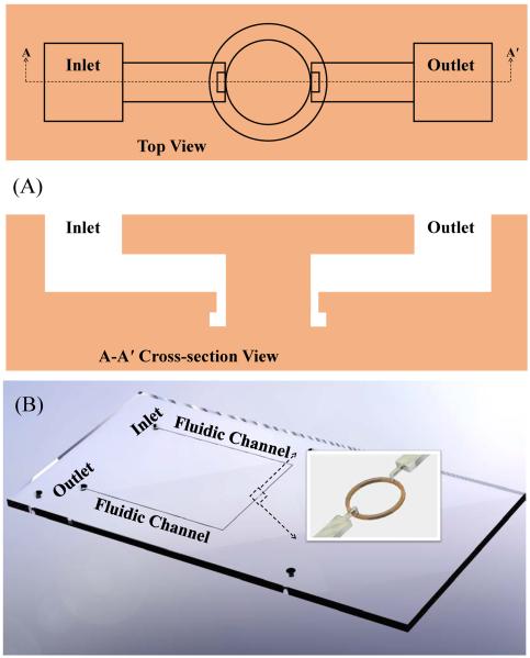
The optofluidic ring resonator laser in this work predominantly comprised of a ring-shaped channel to define the liquid cavity and connecting microfluidic channels used to flow the gain medium solution. All components that build the laser were monolithically incorporated in a piece of fused-silica glass with 3-D freedom. The top and cross-sectional views of the device are illustrated in Fig. 1. The ring cavity was designed to have inner and outer radii and depth of 150 μm, 170 μm, and 40 μm, respectively.
Figure 1.
(A) Top and cross-sectional view of the monolithic optofluidic ring resonator. (B) CAD design of the optofluidic system. Inset shows the details of the ring resonator and the fluidics that delivers the gain solution into the ring resonator.
Owing to the capability of the femtosecond laser to tailor the microfluidic channels in three dimensions, we are able to introduce fluidic channels to transport the gain medium from the inner circumference of the ring where virtually no WGM is present (Fig. 1(A)). This design concept, in contrast to the ring cavity in Ref. 32 where the liquid waveguide channel has to merge with the liquid ring resonator channel for sample delivery, eliminates the possible source of Q-factor degradation35. In addition, the vertical fluidic channels with direct contact to the ring are built to have smaller cross-sectional dimensions (10 μm × 20 μm) than the ring to serve as high flow resistances that guarantee the cavity is constantly filled with adequate amount of light amplification medium irrespective to the device orientation (see the inset in Fig. 1(B)).
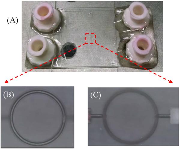
The machining process was started with two fused silica substrates with identical dimensions of 1 inch × 2 inch. The optofluidic components were initially machined separately in these two substrates, with one piece containing the microring and the other encompassing the remaining microfluidic elements, including the input and output fluidic ports. The fabrication process is comprised of three main steps: In the first step, the external boundaries of the various microfluidic elements are written in their respective substrates. This writing step consists of exposing the substrates to femtosecond laser pulses from a Ti:Sapphire laser operating at 800 nm. The pulse width is approximately 100 fs and the repetition rate is set at 250 kHz. The beam is focused into the sample with a long-working distance microscope objective. The laser writing speed ranges from 100 μm/s to 5 mm/s depending on the local geometry of the optofluidic element. The laser pulse energy is adjusted so that there is no material ablation associated with this first step. Both transverse and longitudinal polarizations of the laser beam are used for the exposure. After the laser exposure is completed, the fused-silica substrates are immersed in a low-concentration aqueous solution of hydrofluoric acid. The specimens are polished and rinsed multiple times. Finally, the two substrates are aligned in a clean room and fused together in a high-temperature furnace to form a monolithic optofluidic system. The photograph of the laser-machined device and the microphotograph of the microring cavity are shown in Fig. 2. Figs. 2(B) and (C) present the images of the microring and adjoining fluidic channels taken at different focal lengths. The optical measurements suggest that the separation distance between the ring and parallel fluidic channels is approximately 100 μm, which is in agreement with the design specification. Fig. 2(C) also evidently points out that the orthogonal fluidic channels which directly contact the ring are routed from the inner circumference of the ring.
Figure 2.
(A) Picture of the optofluidic ring resonator laser system. (B) and (C) Microscopic pictures of the optofluidic ring resonator focused on the ring and the fluid delivery channel, respectively.
Experimental
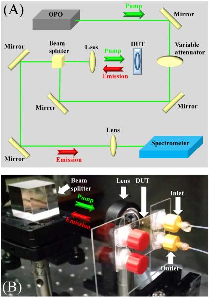
The optofluidic laser was tested according to the measurement setup outlined in Fig. 3. Chemically inert polytetrafluoroethylene (PTFE) tubes with an inner diameter of 300 μm were attached to the input and output fluidic ports as shown in Fig. 3(B). The RG6 dye was dissolved in quinoline: the concentration was 1 mM. The gain solution was then injected into the fluidic channel at a constant flow rate of 3 μL/min using a syringe pump. The aqueous cavity was formed as the active solution with a higher refractive index (1.62) than that of the circumambient fused-silica (1.46) inhabits the ring channel. Next, nanosecond pulses at 532 nm wavelength with 20 Hz repetition rate were launched from an optical parametric oscillator to excite the cavity. The pump beam was focused to a spot area of 0.33 mm2 on the sample by using a cylindrical lens. The coherent light output was emitted from the optofluidic cavity and recorded by a spectrometer (Horiba iHR550, 2400 g/mm grating, spectral resolution: ~0.05 nm, unless otherwise noted) (Fig. 3(A)).
Figure 3.
(A) Schematic of the measurement setup. (B) A close-up view of the device under test during measurement.
Results and discussion
Fig. S1 plots the evolution of the emission from the ring resonator when the pump intensity increases. At low pump intensity, only broad fluorescence centered around 567 nm appears. With further increase in pump, multiple laser emission peaks emerge at the red-side of the fluorescence spectrum. Fig. 4(A) shows the high resolution lasing spectra, which allows us to distinguish each lasing peak. The free-spectral-range (FSR) of approximately 0.184 nm is clearly seen near the wavelength of 572 nm. This FSR is very close to the theoretical prediction of 0.189 nm using FSR = λm2 /(2πrnEff), where λm=572 nm, r=170 μm, nEff=1.62, which suggests that the laser mode travels along the outer rim of the ring resonator, as expected. At pump intensity well above the threshold, a small blue shift in the lasing peak is observed, consistent with what was previously reported36. Fig. 4(B) displays the spectrally integrated laser emission as a function of the pump intensity. The lasing threshold is approximated 15 μJ/mm2. To further confirm the laser emission, additional experiments were performed with lower concentrations of RG6 dye in quinoline. Blue shifts in the laser emissions accompanied by attenuations in output peak intensity were recorded as the concentration of RG6 was lowered from 1 to 0.5 and 0.38 mM while preserving the same pump intensity as shown in Figs. 5(A)–C). The dependence of emission wavelengths on the dye concentrations has been previously studied36,37 and can be accounted for by the dye laser theory presented in the Supplementary Information. The versatility of the optofluidic ring resonator laser lies in its capability to conveniently change the solvent (and gain medium as well). Fig. S8 shows that the lasing emission can easily be achieved with R6G dissolved in chlorobenzene (n=1.524).
Figure 4.
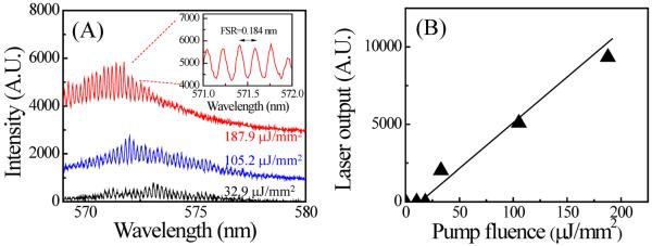
(A) Lasing spectrum of the optofluidic ring resonator dye laser with a pump fluence of 187.9 μJ/mm2 per pulse, 1 mM of R6G dye in quinoline, and a flow rate of 3 μL/min. The spot size of the OPO pumping laser beam was approximately 0.33 mm2. A 2400 g/mm grating was used to achieve high spectral resolution (~0.05 nm). Broad fluorescence background is removed. Spectra are vertically shifted for clarity. Inset: A magnified portion around 572 nm, showing a free spectral range of 0.184 nm. Wider spectral coverage lasing spectra below and just above the threshold are given in Fig. S1. (B) Spectrally integrated (569 nm – 576 nm) laser output as a function of pump fluence extracted from (A). The lasing threshold is approximately 15 μJ/mm2. Solid line is the linear fit above the threshold.
Figure 5.

Blue shifts in the laser emissions accompanied by reduction in output peak intensity as the concentration of RG6 dye was decreased from 1 mM (A) to 0.5 mM (B) and finally to 0.38 mM (C) while keeping the same pump fluence (105.2 μJ/mm2). All spectra are normalized with respect to the highest intensity peak recorded in Fig. 5(A).
Success of ring resonator fabrication by femtosecond laser writing technology is reflected in the resonator's bare cavity Q-factor, Q0 (i.e., the Q-factor in the absence of the gain medium). The Q-factor in the previous work, although not reported, is expected to be rather low due to the low reflectivity of the mirrors15. In the current work, it is difficult to directly measure Q0. However, as detailed in the Supplementary Information, the lasing threshold analysis is able to provide quite accurate Q0 estimation. Based on the lasing fluence threshold of 15 μJ/mm2, we estimate Q0=3.3×10⁴.
It is well known that Q0 is primarily determined by:
| (1) |
where QRad, QSol, and QSc are the Q-factors due to the radiative loss, solvent absorption, and loss resulting from wall scattering. Among the three contributing Q-factors, the loss due to radiation is known to be very small (QRad < 1011)38 due to the relatively large ring radius (170 μm) and high refractive index contrast (Δn~0.17). QSol = 2πnSol/λLαSol, where λL and αSol are respectively the lasing wavelength and the absorption coefficient of the solvent. For quinoline, αSol = 1.1 cm−1 (see Fig. S6), which results in QSol = 1.6×10⁵. Thus, we can conclude that QSc = 4.2×10⁴ and Q0 is mainly determined by the losses due to light scattering from the fused-silica walls and absorption in quinoline. Note that although Q0 (or QSc) is 20–30 times lower than the best previously reported femtosecond laser fabricated ring resonator (Q = 106)39, which underwent CO2 laser annealing, it still represents one of the best cavities in optofluidic lasers (for example, the Q-factor for DFB and Fabry-Pérot are usually on the order of 103 or lower). Such achievement suggests the feasibility of using a femtosecond laser to create high quality optical cavities.
Conclusions and future work
An integrated optofluidic ring resonator laser in a fused-silica glass substrate has been successfully designed, fabricated, and characterized. The manufacturing procedure of this optofluidic laser is unique and compelling for various applications as it offers maskless and flexible fabrication process, easy assembly, excellent device robustness, no post-fabrication processes, quick prototyping, and relatively low cost. The bare cavity Q-factor of 3.3×10⁴ has been achieved, suggesting that the femtosecond writing technology can be used to create high quality cavities.
Several characteristics of this proof-of-concept device are entitled for further investigations. First, we will incorporate another liquid ring resonator nearby to achieve single mode of laser operation via the Vernier effect31,32. In addition, since each ring resonator can be independently controlled, a wavelength-tunable laser will be built by changing the solution in one of the rings. A waveguide can also be fabricated in the vicinity of the ring so that the laser emission can be directionally coupled out. Furthermore, we will explore other high index and low absorption solvents40 as alternatives to quinoline (see example in Fig. S8). With those solvents, we expect Q0 to approach QSc, which is caused during femtosecond laser fabrication. Post-fabrication annealing will also be employed to further reduce scattering and increase QSc. Finally, biolasers will be explored where gain media such as nanoparticles, biological molecules, and cells will be flowed through the ring resonator5.
Supplementary Material
Acknowledgements
The authors thank the National Institutes of Health (NIBIB-1R21EB016783) and National Science Foundation (ECCS-1303499) for financial supports, Seung Yup Lee and Dr. Mary-Ann Mycek for assistance with the fluorescence lifetime measurement, Zhizheng Zhang for assistance in acquiring SEM images, and Dr. Alper Kiraz and Dr. Aghapi Mordovanakis for valuable discussions.
References
- 1.Fan X, White IM. Optofluidic microsystems for chemical and biological analysis. Nature Photon. 2011;5:591–597. doi: 10.1038/nphoton.2011.206. [DOI] [PMC free article] [PubMed] [Google Scholar]
- 2.Psaltis D, Quake SR, Yang C. Developing optofluidic technology through the fusion of microfluidics and optics. Nature. 2006;442:381–386. doi: 10.1038/nature05060. [DOI] [PubMed] [Google Scholar]
- 3.Schmidt H, Hawkins AR. The photonic integration of non-solid media using optofluidics. Nature Photon. 2011;5:598–604. [Google Scholar]
- 4.Li Z, Psaltis D. Optofluidic dye lasers. Microfluid. Nanofluid. 2007;4:145–158. [Google Scholar]
- 5.Fan X, Yun S-H. The potential of optofluidic biolasers. Nature Methods. 2014;11:141–147. doi: 10.1038/nmeth.2805. [DOI] [PMC free article] [PubMed] [Google Scholar]
- 6.Aubry G, Méance S, Haghiri-Gosnet A-M, Kou Q. Flow rate based control of wavelength emission in a multicolor microfluidic dye laser. Microelectron. Eng. 2010;87:765–768. [Google Scholar]
- 7.Gersborg-Hansen M, Kristensen A. Tunability of optofluidic distributed feedback dye lasers. Opt. Express. 2007;15:137–142. doi: 10.1364/oe.15.000137. [DOI] [PubMed] [Google Scholar]
- 8.Li Z, Zhang Z, Scherer A, Psaltis D. Mechanically tunable optofluidic distributed feedback dye laser. Opt. Express. 2006;14:10494–10499. doi: 10.1364/oe.14.010494. [DOI] [PubMed] [Google Scholar]
- 9.Sun Y, Shopova SI, Wu C-S, Arnold S, Fan X. Bioinspired optofluidic FRET lasers via DNA scaffolds. Proc. Natl. Acad. Sci. USA. 2010;107:16039–16042. doi: 10.1073/pnas.1003581107. [DOI] [PMC free article] [PubMed] [Google Scholar]
- 10.Chen Q, Ritt M, Sivaramakrishnan S, Sun Y, Fan X. Optofluidic lasers with a single molecular layer of gain. Lab Chip. 2014;14:4590–4595. doi: 10.1039/c4lc00872c. [DOI] [PMC free article] [PubMed] [Google Scholar]
- 11.Chen Q, Zhang X, Sun Y, Ritt M, Sivaramakrishnan S, Fan X. Highly sensitive fluorescent protein FRET detection using optofluidic lasers. Lab Chip. 2013;13:2679–2681. doi: 10.1039/c3lc50207d. [DOI] [PubMed] [Google Scholar]
- 12.Gather MC, Yun SH. Single-cell biological lasers. Nature Photon. 2011;5:406–410. [Google Scholar]
- 13.Sun Y, Fan X. Distinguishing DNA by Analog-to-Digital-like Conversion by Using Optofluidic Lasers. Angew. Chem. Int. Ed. 2012;51:1236–1239. doi: 10.1002/anie.201107381. [DOI] [PubMed] [Google Scholar]
- 14.Zhang X, Lee W, Fan X. Bio-switchable optofluidic lasers based on DNA Holliday junctions. Lab Chip. 2012;12:3673–3675. doi: 10.1039/c2lc40183e. [DOI] [PubMed] [Google Scholar]
- 15.Cheng Y, Sugioka K, Midorikawa K. Microfluidic laser embedded in glass by three-dimensional femtosecond laser microprocessing. Opt. Lett. 2004;29:2007–2009. doi: 10.1364/ol.29.002007. [DOI] [PubMed] [Google Scholar]
- 16.Helbo B, Kristensen A, Menon A. A micro-cavity fluidic dye laser. J. Micromech. Microeng. 2003;13:307. [Google Scholar]
- 17.Kou Q, Yesilyurt I, Escalier G, Galas JC, Coureau L, Chen Y. Photonics Asia 2004. International Society for Optics and Photonics; 2004. Microfluidic dye laser integration in a lab-on-a-chip device; pp. 112–115. [Google Scholar]
- 18.Shopova SI, Zhu H, Fan X, Zhang P. Optofluidic ring resonator based dye laser. Appl. Phys. Lett. 2007;90:221101. [Google Scholar]
- 19.Chen Y, Li Z, Zhang Z, Psaltis D, Scherer A. Nanoimprinted circular grating distributed feedback dye laser. Appl. Phys. Lett. 2007;91:051109. [Google Scholar]
- 20.Song W, Vasdekis AE, Li Z, Psaltis D. Optofluidic evanescent dye laser based on a distributed feedback circular grating. Appl. Phys. Lett. 2009;94:161110. [Google Scholar]
- 21.Vannahme C, Smith CL, Christiansen MB, Kristensen A. Emission wavelength of multilayer distributed feedback dye lasers. Appl. Phys. Lett. 2012;101:151123. [Google Scholar]
- 22.Wienhold T, Breithaupt F, Vannahme C, Christiansen MB, Dörfler W, Kristensen A, Mappes T. Diffusion driven optofluidic dye lasers encapsulated into polymer chips. Lab Chip. 2012;12:3734–3739. doi: 10.1039/c2lc40494j. [DOI] [PubMed] [Google Scholar]
- 23.Aubry G, Kou Q, Soto-Velasco J, Wang C, Meance S, He J, Haghiri-Gosnet A. A multicolor microfluidic droplet dye laser with single mode emission. Appl. Phys. Lett. 2011;98:111111. [Google Scholar]
- 24.Kou Q, Yesilyurt I, Chen Y. Collinear dual-color laser emission from a microfluidic dye laser. Appl. Phys. Lett. 2006;88:091101. [Google Scholar]
- 25.Kuehne AJC, Gather MC, Eydelnant IA, Yun S-H, Weitzad DA, Wheeler AR. A switchable digital microfluidic droplet dye-laser. Lab Chip. 2011;11:3716–3719. doi: 10.1039/c1lc20405j. [DOI] [PubMed] [Google Scholar]
- 26.Zhen B, Chua S-L, Lee J, Rodriguez AW, Liang X, Johnson SG, Joannopoulos JD, Soljačić M, Shapira O. Enabling enhanced emission and low-threshold lasing of organic molecules using special Fano resonances of macroscopic photonic crystals. Proc. Natl. Acad. Sci. USA. 2013;110:13711–13716. doi: 10.1073/pnas.1311866110. [DOI] [PMC free article] [PubMed] [Google Scholar]
- 27.Lee J, Zhen B, Chua S-L, Qiu W, Joannopoulos JD, Soljačić M, Shapira O. Observation and differentiation of unique high-Q optical resonances near zero wave vector in macroscopic photonic crystal slabs. Phys. Rev. Lett. 2012;109:067401. doi: 10.1103/PhysRevLett.109.067401. [DOI] [PubMed] [Google Scholar]
- 28.De Heyn P, Vermeulen D, Van Thourhout D, Roelkens G. Silicon-on-insulator all-pass microring resonators using a polarization rotating coupling section. IEEE Photon. Technol. Lett. 2012;24:1176–1178. [Google Scholar]
- 29.Griffith A, Cardenas J, Poitras CB, Lipson M. High quality factor and high confinement silicon resonators using etchless process. Opt. Express. 2012;20:21341–21345. doi: 10.1364/OE.20.021341. [DOI] [PubMed] [Google Scholar]
- 30.Momeni B, Yegnanarayanan S, Soltani M, Eftekhar AA, Hosseini ES, Adibi A. Silicon nanophotonic devices for integrated sensing. J. Nanophoton. 2009;3:031001. doi: 10.1109/IEMBS.2010.5625992. [DOI] [PubMed] [Google Scholar]
- 31.Lee W, Li H, Suter JD, Reddy K, Sun Y, Fan X. Tunable single mode lasing from an on-chip optofluidic ring resonator laser. Appl. Phys. Lett. 2011;98:061103. [Google Scholar]
- 32.Li Z. Frequency Control Symposium (FCS), 2012 IEEE International. IEEE; 2012. Optofluidic coupled micro-ring resonators for biosensing; pp. 1–4. [Google Scholar]
- 33.Tang SK, Li Z, Abate AR, Agresti JJ, Weitz DA, Psaltis D, Whitesides GM. A multi-color fast-switching microfluidic droplet dye laser. Lab Chip. 2009;9:2767–2771. doi: 10.1039/b914066b. [DOI] [PubMed] [Google Scholar]
- 34.Bellouard Y, Said AA, Dugan M, Bado P. European Symposium on Optics and Photonics for Defence and Security. International Society for Optics and Photonics; Bruges, Belgium: 2005. All-optical, ultra-high accuracy displacement sensors with detection means; pp. 59890V–59891.pp. 59814 [Google Scholar]
- 35.Little BE, Foresi J, Steinmeyer G, Thoen E, Chu S, Haus H, Ippen E, Kimerling L, Greene W. Ultra-compact Si-SiO2 microring resonator optical channel dropping filters. IEEE Photonics Technol. Lett. 1998;10:549–551. [Google Scholar]
- 36.Lacey S, White IM, Sun Y, Shopova SI, Cupps JM, Zhang P, Fan X. Versatile opto-fluidic ring resonator lasers with ultra-low threshold. Opt. Express. 2007;15:15523–15530. doi: 10.1364/oe.15.015523. [DOI] [PubMed] [Google Scholar]
- 37.Vezenov DV, Mayers BT, Wolfe DB, Whitesides GM. Integrated fluorescent light source for optofluidic applications. Appl. Phys. Lett. 2005;86:041104. [Google Scholar]
- 38.Gorodetsky ML, Savchenkov AA, Ilchenko VS. Ultimate Q of optical microsphere resonators. Opt. Lett. 1996;21:453–455. doi: 10.1364/ol.21.000453. [DOI] [PubMed] [Google Scholar]
- 39.Lin J, Yu S, Ma Y, Fang W, He F, Qiao L, Tong L, Cheng Y, Xu Z. On-chip three-dimensional high-Q microcavities fabricated by femtosecond laser direct writing. Opt. Express. 2012;20:10212–10217. doi: 10.1364/OE.20.010212. [DOI] [PubMed] [Google Scholar]
- 40.Stone J. Measurements of the absorption of light in low-loss liquids. J. Opt. Soc. Am. 1972;62:327–333. [Google Scholar]
Associated Data
This section collects any data citations, data availability statements, or supplementary materials included in this article.


