Abstract
Electrospinning from the melt, in contrast to from solution, is an attractive tissue engineering scaffold manufacturing process as it allows for the formation of small diameter fibers while eliminating potentially cytotoxic solvents. Despite this, there is a dearth of literature on scaffold formation via melt electrospinning. This is likely due to the technical challenges related to the need for a well-controlled high temperature setup and the difficulty in developing an appropriate polymer. In this paper, a biodegradable and thermally stable polyurethane (PU) is described specifically for use in melt electrospinning. Polymer formulations of aliphatic PUs based on (CH2)4-content diisocyanates, polycaprolactone (PCL), 1,4-butanediamine and 1,4-butanediol (BD) were evaluated for utility in the melt electrospinning process. The final polymer formulation, a catalyst-purified PU based on 1,4-butane diisocyanate, PCL and BD in a 4/1/3 molar ratio with a weight-average molecular weight of about 40 kDa, yielded a nontoxic polymer that could be readily electrospun from the melt. Scaffolds electrospun from this polymer contained point bonds between fibers and mechanical properties analogous to many in vivo soft tissues.
Keywords: aliphatic polyurethanes, biodegradable polymer, melt electrospinning, tissue engineering
Introduction
A number of polymers have been used in melt electrospinning. However, the use of polyurethanes (PUs) in melt electrospun scaffolds is not well represented in the literature despite the attractive properties of this class of polymers1. The seminal melt electrospinning work of Larrondo and Manley2-4 focused on polyethylene and polypropylene. Other polymers that have been melt electrospun include polyester5, poly(lactic acid)6, poly(ethylene glycol)7, and a blend of poly(ethylene oxide-block-caprolactone) with polycaprolactone (PCL)8. PUs contain properties which are superior to many commonly used polymers for tissue engineering scaffolds9. PUs can be designed such that the finished material is thermally stable, degradable, nontoxic, and with tunable mechanical properties10-12. A sub-class of PUs, segmented linear elastomeric biodegradable urethane block copolymers consisting of alternating backbone hard and soft segments, are attractive for tissue engineering, primarily due to their molecular design flexibility providing a broad range of properties including biodegradability. Most commercially available, linear PU block copolymers are based on aromatic diisocyanates such as 4,4’-diphenylmethane diisocyanate and toluene diisocyanate11. Although several medical devices comprised of PU elastomers containing aromatic cycles in their hard segments were approved by the regulatory authorities in past years for medical applications, these are not biodegradable formulations and the products of decomposition (if, indeed, decomposition occurs) may be toxic13, 14. Some groups have worked to develop less toxic degradable aliphatic diisocyanate-based PUs15-17; however, such a polymer has yet to be melt electrospun.
The goal of the current work was to develop a novel degradable and biocompatible aliphatic PU which could be formed into scaffolds via melt electrospinning. The PU formulations investigated in this study were based on various combinations of PCL diol, with number-average molecular weight (MW) about 1250 Da, 2,6-diisocyanato methyl caproate (lysine diisocyanate (LDI)), 1,4-butanediisocyanate (BDI), 1,4-butanediamine (BDA) (putrescine), and 1,4-butanediol (BD). PU copolymers based on (CH2)4- content diisocyanates such as LDI and BDI are expected to be nontoxic since the product of hydrolytic degradation, BDA, is nontoxic18. Similarly, the use of PCL as the soft segment is common due to its biocompatibility and biodegradability10. The polymer composition and weight-average MW (Mw) were optimized for melt electrospinning. The final polymer was evaluated for cytotoxicity, and mechanical properties of electrospun scaffolds were determined.
Materials and Methods
Polymer synthesis
All chemicals were purchased from Aldrich Chemical Company, Inc. (Milwaukee, WI), unless otherwise noted. The synthesized polymers were made via the standard procedure of multi-step addition polymerization in N,N-dimethylacetamide (DMAc) solvent, described elsewhere19-20. This general method allows the synthesis of PUs with a variety of compositions with precision and reproducibility19, 20. The polymerization pathway can be briefly described by three main steps:
Reaction between PCL and the variable molar excess of isocyanate (NCO) groups of either LDI or BDI yields intermediates end-capped with isocyanate groups (prepolymers).
Either BDA or BD with variable molar excess of amino (NH2) or hydroxyl (OH) groups were used as chain extenders to provide a polymerization with the isocyanate prepolymer in DMAc to create a low MW PU end-capped with either NH2 or OH groups. A reaction between aliphatic NCO groups of the prepolymer and NH2 groups of BDA was carried out at room temperature in DMAc. Dibutyltin dilaurate (DBTDL) served as the catalyst accelerating reaction between aliphatic NCO groups of the prepolymer and OH groups of BD at approximately 80°C in DMAc.
The low MW PU was then combined with a monomeric diisocyanate in a gradual approach to stoichiometry21, 22 to yield a high MW polymer of specific Mw.
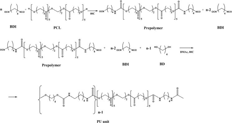
The simplified scheme of the urethane polymerization process based on PCL, BDI and BD is presented in Figure 1.
Figure 1.
Simplified synthesis scheme of a thermally stable polyurethane based on BDI, PCL and BD
Polymer purification
In order to remove methanol-soluble catalyst after the last synthesis step, the polymer was precipitated in an excess of methanol at room temperature. After filtration, remaining polymer was washed three more times in fresh methanol at room temperature (12 hour washing steps). These steps were followed by two 12 hour rinses in fresh, circulating DI water to remove methanol and DMAc. The polymer was finally dried under vacuum at approximately 60 - 65°C for at least 12 hours.
Electrospinning
Scaffolds were electrospun using a custom apparatus described previously23. Briefly, the apparatus consists of a melt chamber mounted on an enclosure that housed a collecting surface and electrode. The melt chamber was made up of a metal sleeve that terminated in a 0.5 mm diameter nozzle. A pair of band heaters was secured around the melt chamber to heat the as-received purified and dried polymer. A grounding rod was placed inside the polymer which terminated at the external surface of a custom poly(ether ether ketone) cap screwed onto the melt chamber. The positive electrode was mounted below the collection surface. The collection surface, an adhesive backed copper strip affixed to a glass microscope slide, was mounted on a 3-axis stage (404150XR, Parker Daedal, Harrison City, PA) that moved the collector in concentric circles beneath the electrospinning nozzle. A high voltage power supply (RP-50-100, Del, Valhalla, NY) supplied a potential of 30 kV between the grounding rod and positive electrode.
The distance between positive and ground electrodes was set at 13 cm, and melt temperature set at 220 - 240°C for all runs. The voltage and electrode distance used provided an electric field strength sufficient to form fibers into an electrospun mat on the collector. A low electric field strength was not strong enough to overcome the surface tension of the polymer droplet24, while a high electric field strength increased the bending instability of the electrospun fiber. Therefore, for a given applied voltage a large distance between electrodes did not result in formation of a Taylor cone and subsequent fiber formation while a short electrode distance caused the fiber to miss the target collector.
After electrospinning, samples were immediately transferred to a 60 mm Petri dish, sealed with Parafilm, and placed in a desiccator until cytotoxicity testing began. Electrospun scaffolds were photographed with a 6.1 megapixel digital camera (D70S, Nikon, Melville, NY).
Cytotoxicity
Cytotoxicity screening was performed on electrospun mats to evaluate suitability as a biomaterial. Cytotoxicity testing was based on the United States Pharmacopeia in vitro biological reactivity “elution test.”25 This test determines the reactivity of leachates from polymeric materials to mammalian cell cultures. Included in the test is a description of standardized grades, 0 - 4, that correlate cell morphology to a description of reactivity. According to the test specifications, a grade of 0 correlates to an absence of cell lysis, while a grade of 4 correlates to nearly total destruction of the cell layer.
Prior to cytotoxicity testing, electrospun samples were washed and sterilized. Briefly, samples were placed in a dilute solution of RBS 35 detergent and sonicated for 30 minutes. The samples were then rinsed with DI water and sonicated in DI water several times using fresh DI water each time to remove most or all of the detergent. Samples were dried overnight in a biological safety cabinet, and, once dried, sterilized using ultraviolet (UV) light. Samples were irradiated for 30 min on each side at a distance of 14 cm beneath the lamp which was previously shown to be sufficient for sterilization of electrospun fibers26. Subsequently, samples were incubated at 37°C and 5% CO2 for 24 hours in Dulbecco's modified eagle's medium (DMEM) at a weight-to-volume ratio of 4 g per 20 ml to obtain the polymer extract. High density polyethylene and latex surgical gloves served as the negative and positive reference controls, respectively.
Human fetal foreskin fibroblast cells (SCRC-1041, ATCC, Manassas, VA) were cultured at 37°C and 5% CO2. Cells were plated at 2×10⁵ cells/well in 6-well tissue culture plates or 5×10⁴ cells/well in 24-well tissue culture plates. When a cell monolayer was achieved, the medium was aspirated and replaced with complete DMEM containing extracts from test sample and control preparations. For the 6-well and 24-well culture plates 0.8 ml and 0.1 ml of extracts were added respectively. After 48 hours in culture, cell monolayers were examined microscopically (Microphot-SA, Nikon Inc., Tokyo, Japan) for the presence of morphological changes, reduction in cell density or lysis. Samples were tested in triplicate.
Polymer optimization for electrospinning
The change in Mw from the melt electrospinning process was determined by computing percent change in Mw values between the as-received polymer and electrospun scaffold using gel permeation chromatography (GPC). A series of four new polymers with variable Mw based on the component molar ratio of PU-5 (Table 1) were made via the standard procedure of solution polymerization in DMAc described above. During the synthesis, four aliquots of the polymer solutions were withdrawn from the reaction flask at the last step in various precalculated equivalent OH/NCO group ratios: 1.15/1 (PU-5-1), 1.10/1 (PU-5-2), 1.05/1 (PU-5-3), and 1.00/1 (PU-5-4). Each sample was purified separately following the procedure described above.
Table 1.
Electrospun fiber appearance related to polymer composition.
| Polymer Code | Composition and Molar Ratio | Hard Segment %wt | Soft Segment %wt | Appearance |
|---|---|---|---|---|
| PU-1 | PCL/LDI/BDA = 1/2/1 | 29.05 | 70.95 | Weak, yellowed fibers |
| PU-2 | PCL/LDI/BDA = 1/4/3 | 46.95 | 53.05 | Robust, slightly yellowed fibers |
| PU-3 | PCL/LDI/BDA = 1/8/7 | 64.78 | 35.22 | Electrospray and drips |
| PU-4 | PCL/BDI/BDA = 1/4/3 | 39.38 | 60.62 | Unable to melt polymer |
| PU-5 | PCL/BDI/BD = 1/4/3 | 35.22 | 64.78 | Good quality fibers |
Electrospinning was performed at an appropriate temperature required to melt each polymer. In a pilot test, the temperature in the melt chamber was raised from 200°C until a droplet of polymer formed and was held in place at the nozzle. The surface tension in the polymer maintained the droplet's shape and position. The maintenance of the droplet shape and position was a critical precursor to Taylor cone and fiber formation once the electric field was applied. The temperature necessary to melt the polymer and form a droplet was considered the appropriate melt electrospinning temperature.
Three electrospun samples for each polymer with different Mw values were used for MW measurements. Using statistical software (SPSS, Chicago, IL), a one-way independent ANOVA and post hoc tests (Bonferroni, Tukey, and Games-Howell) were performed to determine statistical significance (p<0.05) of differences in MW between polymers.
Gel permeation chromatography
In preparation for gel permeation chromatography (GPC) analysis, polymer samples were dissolved in HPLC-grade N,N-dimethylformamide (DMF) then filtered with a disposable 0.2 μm syringe filter. GPC analysis was performed using three Tosoh TSK-GEL columns (TSK-α±3000, α±3000, α±4000) connected in series to a Viscotek GPCmax (VE2001, Viscotek, Houston, TX) and Viscotek RI and UV detectors (VE3580 and VE3210, respectively, Viscotek, Houston, TX). The mobile phase was DMF containing 0.1 wt% LiBr. Mw distributions were determined relative to a series of poly(methyl methacrylate) standards.
Fiber diameter
Mean fiber diameter was determined by measuring individual fibers based on un-biased stereological techniques. To accomplish this measurement, five equidistant 12 μm sections were cut from scaffolds embedded in optimal cutting temperature embedding media in triplicate. Sections were digitized with an upright microscope at 2X by taking random 0.5 mm2 images. Images were imported into Image J software (National Institutes of Health, Bethesda, MD) for analysis of fiber diameter with a dissector probe. This method yielded more than 200 measurements per scaffold.
Cell seeding
A primary cell culture was established from anterior cruciate ligaments fibroblasts. Ligaments were aseptically harvested from freshly sacrificed adolescent (3-5 months) Yorkshire pigs. In a biosafety cabinet, ligaments were minced to facilitate cell outgrowth according to Protocol 11.4 of Freshney14. Minced tissue was cultured in cell culture medium in an incubator with a 37°C humidified atmosphere of 5% CO2. The medium consisted of Dulbecco's Modified Eagle's Medium (D5796, Sigma-Aldrich, St. Louis, MO) supplemented with 10% fetal bovine serum (SH3008802, Fisher Scientific, Pittsburg, PA), 1% L-glutamine (G7513, Sigma-Aldrich, St. Louis, MO), 1% 100X antibiotic/antimicrobial (15240-062, Invitrogen, Carlsbad, CA), and Hepes buffer (H0887, Sigma-Aldrich, St. Louis, MO). Fibroblast migration typically took 5-7 days during which medium was changed every three days. Once cells approached 70% confluence the minced tissue was removed, and then cells were re-plated onto tissue culture flasks. Cells from passage 3 were re-suspended in medium containing 10% Dimethyl Sulfoxide and stored in -70°C liquid N2 until use.
Prior to cell seeding, electrospun scaffolds were washed and sterilized as described above. Fibroblasts from passage 6 were seeded onto fibronectin-coated scaffolds at a concentration of 1×10⁶ cells/ml. Seeded scaffolds were cultured for four weeks prior to fixation with Karnovsky's fixative (15720, Electron Microscopy Sciences, Hatfield, PA).
Scanning electron microscopy
High-resolution SEM (HR-SEM, Sirion, FEI Company, Eindhoven, The Netherlands) was used to visualize sample morphology and fiber bonding. The HR-SEM micrographs were taken using a voltage of 5 kV for the electrospun samples. Prior to visualization, samples were sputter-coated for 30 seconds forming an approximately 10 nm thick gold layer in order to prevent charging.
Mechanical Testing
Testing of scaffolds was performed following ASTM standard D5035 (Standard Test Method for Breaking Force and Elongation of Textile Fabrics - Strip Method). Samples were cut into rectangular test strips with a width of 5 mm and length of 26 mm. Five vertically oriented samples were subjected to a tensile test in an Instron testing machine (5543, Instron, Norwood, MA) at room temperature at a strain rate of 300 mm/min until sample failure. For strain calculations, the initial gauge length was taken as the grip-to-grip distance. For stress calculations, the bulk thickness of each sample was measured in three locations with a digital micrometer while the sample was at zero displacement. Measurements were taken at both ends and the center of the sample gauge length. The mean of these three measurements constituted bulk scaffold thickness. To compute accurate cross sectional area, bulk width and thickness measurements were multiplied by the fiber area fraction. Fiber area fraction was determined with a similar sampling technique used to measure fiber diameters. The area fraction was determined using Image J. The elastic modulus was computed from the linear region of the stress-strain curve, defined as the portion which gave the best fit linear regression (R2 > 0.99).
Results and discussion
The ability to form tissue engineering scaffolds with PUs is advantageous due to their wide acceptance as biomedical polymers, excellent mechanical properties and biocompatibility27. In the present study, biodegradable segmented linear PU block copolymers with a backbone consisting of two types of segments based on three constituents, oligodiol, diisocyanate and difunctional chain extender have been synthesized.
Polymer formulation and fiber diameter
In order to determine an optimal biodegradable polymer composition with segmental concentration suitable for melt electrospinning, three polymers were synthesized and electrospun in a pilot study. The ideal polymer must possess an appropriate melting temperature, melt viscosity at the temperature of electrospinning, high thermal stability, and also be a good fiber-forming composition under electrospinning conditions.
To melt electrospin successfully, the polymer composition should be designed to have an appropriate temperature “gap” between melting temperature (Tm) and temperature of thermal degradation (Td). In other words, the macromolecular structure should be engineered for a Tm high enough to break hydrogen bonds between hard segments in adjacent chains, but lower than the Td so covalent chemical bonds in the polymer backbone are not cleaved.
In a pilot study, the polymers spanned a broad range of compositions with increasing hard segment concentrations and corresponding molar ratios of PCL/LDI/BDA: 1/2/1 (PU-1), 1/4/3 (PU-2), 1/8/7 (PU-3) (Table 1). It was expected that the PCL segment contributed both biodegradability and elasticity. We assumed that degradation products of such a polymer would be nontoxic due to the polymer composition consisting of ester linkages (hydrolyzing to carboxylic acid and hydroxyl) in the PCL molecular chain, urea groups in the LDI-BDA hard segment, and lysine-like structures for both LDI and BDA. We hypothesized that optimal mechanical properties of the polymers based on chosen components could be found in the concentration range of the hard segment between about 30 and 65%wt and corresponding concentration range of the soft segment between about 35 and 70%wt. PU-1, PU-2, and PU-3 were electrospun at melt temperatures of 220°C, 230°C, and 240°C, respectively.
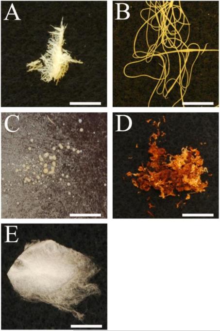
Each polymer formulation yielded a different result. The electrospun mat from PU-1 was composed of yellowed fibers (Figure 2A) that were clumped together. Minor mechanical manipulation readily separated the fibers and broke them apart. The significant color change in this polymer was likely a result of thermal degradation during the melt electrospinning process, attributed to the relatively high soft segment concentration. Electrospun PU-3 was devoid of fibers, containing only drops on the collection surface (electrospray) (Figure 2C), attributed to the high hard segment fraction making the polymer quite brittle. Of the three initial polymers, electrospun PU-2 was the most promising (Figure 2B), though the yellowed polymer appearance was taken as possible evidence of thermal degradation.
Figure 2.
Electrospun: A) PU-1; B) PU-2; C) PU-3; D) PU-4; E) PU-5. Scale bar is 10 mm.
LDI was initially chosen because there is experimental evidence that the pendant methyl ester group in LDI is rapidly hydrolyzed, followed by slower hydrolysis of urethane bonds in the backbone chain28, and the product of its degradation has a nontoxic lysine-like structure. However, at the temperatures required for electrospinning, 220 - 240°C, degradation of the LDI based PU occurred as evidenced by the yellowing of the polymer (Figure 2A, B, and C).
This result prompted further exploration for a more thermally stable formulation. PU-4 was made with the same component molar ratio as PU-2 and similar segmental weight concentration, but based on the use of BDI instead of LDI with the assumption that the structure of the BDI-BDA hard segment would provide increased thermal stability. After 25 minutes at 300°C, PU-4 did not melt resulting in polymer that was a deep orange/yellow burnt color (Figure 2D). The inability to melt was likely due to the structure of the BDI-BDA hard segments that closely pack in the hard domains because BDI offers no steric hindrance from a pendant unit as in the LDI structure. This leads to stronger hydrogen bonding in the BDI-BDA domains compared to LDI-BDA.
To improve melt processing, a polymer with a lower melt temperature (Tm) was synthesized with BD replacing BDA as the chain extender, since the hydrogen bonding associated with BDI-BD urethane groups is typically reduced compared to the urea groups of the BDI-BDA domain. Thus, the final polymer formulation, PU-5, was based on PCL as an elastic segment, BDI as a fragment of the hard segment and BD as chain extender (molar component ratio 1/4/3). Electrospun PU-5 yielded a homogenous fibrous scaffold with little to no visual evidence of thermal degradation (Figure 2E). With the application of an electrostatic field, a continuous single fiber ejected from the Taylor cone. No beads were observed within the scaffold as a result of dripping or electrospray during electrospinning. This polymer was further evaluated in the remainder of this study.
The higher viscosities associated with melt electrospinning typically yield fiber diameters that are orders of magnitude larger than those produced by solution electrospinning which are mostly in the sub-micron range. The relationship between viscosity and diameter can be attributed to the interplay of forces involved in electrospinning. The applied electrostatic field energizes the polymer causing bending instability that violently whips the fiber resulting in cross-section area reduction. A more viscous polymer will resist the bending instability due to increased fiber stiffness thereby stabilizing the cross-sectional area. While our melt-electrospun fibers are relatively large compared to those from solution electrospinning, the mean diameter of melt electrospun PU-5 fibers, 11.2 ± 2.3 μm, would be suitable for scaffolds intended to replace many soft tissue structures. For example, the anterior cruciate ligament contains collagen fibers in the 1 - 20 μm range29.
Cytotoxicity
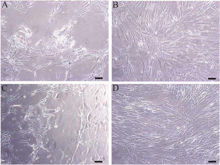
All positive controls resulted in a grade of least 3 (moderate reactivity) while all negative controls resulted in a grade of 0 (no reactivity). Representative images of positive and negative controls are seen in Figure 3A and B, respectively. The sheet of cells exposed to negative control eluent is intact and continuous with spindle-shaped cells. In contrast, cells exposed to positive control eluent form a discontinuous sheet. Many of the cells are non-viable and appear to be detached.
Figure 3.
Cytotoxicity results from: A) positive control; B) negative control; C) electrospun PU-5 with DBTDL catalyst; D) electrospun PU-5 without DBTDL catalyst. Scale bar is 100 μm.
Since a preliminary test for cytotoxicity of one of our polymers was positive, residual DBTDL catalyst, having poor solubility in water, was the suspect toxic agent. Before leaching out of the catalyst, PU-5 with DBTDL in both the as-received and electrospun states was found to be cytotoxic achieving grade 3 reactivity. Cells exposed to eluent of pre-washed PU-5 (Figure 3C) became rounded and detached attaining morphology similar to positive controls. Based on this result, the polymer purification procedure described in the methods section was developed. PU-5 purified of catalyst was found to be nontoxic. Cells exposed to eluent from this polymer exhibited no observed change in morphology between these samples and negative controls (Figure 3D). A summary of graded results is shown in Table 2.
Table 2.
United States Pharmacopeia in vitro biological reactivity grades of as-received and electrospun PU polymers.
| Polymer Code | Polymer State | Sample Grade | Negative Control Grade | Positive Control Grade |
|---|---|---|---|---|
| PU-5 with DBTDL catalyst | as-received | 3 | 0 | 3 |
| electrospun | 3 | |||
| PU-5 without DBTDL catalyst | as-received | 0 | 0 | 4 |
| electrospun | 0 |
In vitro cytotoxicity testing has limitations. While in vitro cytotoxicity results typically hold in the in vivo environment27, the test used in the present study should be considered an initial screening for cytotoxicity. The USP in vitro elution protocol specifies cell exposure for 48 hours, thereby giving no indication of long term cell viability. The short-term test does not allow for assessment of degradation products from the electrospun polymer. However, a longer term cell culture also showed no indication of cytotoxicity, described in more detail below.
Polymer optimization for electrospinning
Ideally, polymers for melt electrospinning should not change Mw as a function of processing temperature. The number of chain entanglements is proportional to polymer M as is melt viscosity30. Chain entanglement affects the morphology of fibers since viscosity is important to the formation of uniform electrospun fiber. For example, a lower Mw can lead to the formation of beads on fibers31.
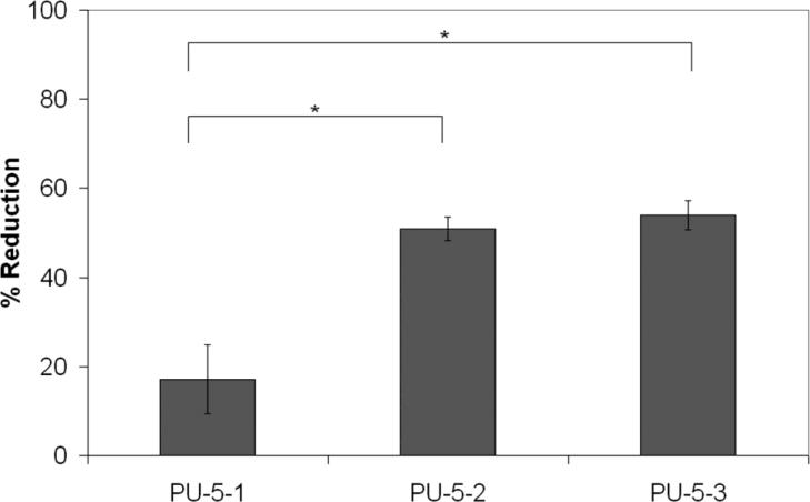
Melt electrospinning had a significant effect on the Mw with PU-5-1 having the least change in Mw. The as-synthesized polymers had Mw's of 39.7, 49.0, 54.0, and 66.8 kDa for PU-5-1, PU-5-2, PU-5-3, and PU-5-4, respectively. PU-5-4 could not be adequately electrospun at any temperature up to 300°C, just yielding beads of yellowed polymer. Polymers PU-5-1, PU-5-2, and PU-5-3 were melt electrospun at 235°C, 240°C, and 247°C, respectively. A significantly lower change (p<0.05) in Mw after melt electrospinning of PU-5-1 compared to PU-5-2 and PU-5-3 was noted (Figure 4). Therefore, despite the relatively high Mw of as-synthesized PU-5-2 and PU-5-3, the greater reduction in Mw during melt electrospinning will unfavorably impact fiber morphology at longer electrospinning times.
Figure 4.
Effect of electrospinning on polymer Mw. Mean + 1 standard deviation.
Morphological characterization and cell interaction
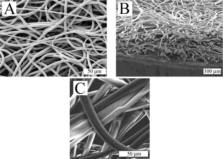
The fibers produced by melt electrospinning PU-5-1 were smooth and uniform, and lacked the beads-on-the-string morphology sometimes observed in solution electrospun fibers (Figure 5A). Macroscopically, scaffolds are highly porous (Figure 5B). The electrospun fibers were neither focused on a particular spot forming a mound nor did they form looped coils which have been observed in melt electrospun scaffolds32; rather, the fibers were evenly distributed throughout the scaffold. Obvious bonds between fibers were not apparent in the sample (Figure 5C). However, manual manipulation of the scaffolds and microscope observation leads to the conclusion that fiber point bonding exists since deformation of an individual fiber would affect adjacent fibers33. If there were no point bonding, individual fibers would pull apart upon application of strain. Point bonding is difficult to quantify in SEM images since a true point bond will have virtually no alteration of fiber morphology at the junction.
Figure 5.
Scanning electron micrographs of electrospun scaffold using PU-5-1: A) Top view; B) Cross-section; C) Top view magnified.
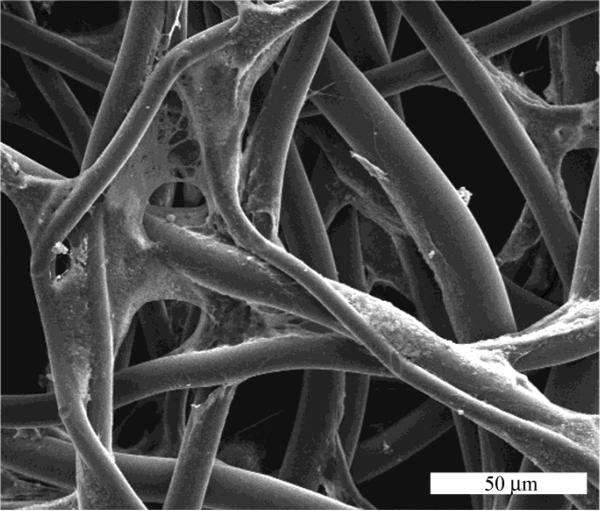
To assess cell infiltration, and to further assess the potential for cytotoxic breakdown products, fibroblasts were grown on scaffolds for up to four weeks. Fibroblasts seeded onto electrospun scaffolds adhered and were observed to assume different morphologies (Figure 6). Some cells assumed a spindly morphology elongating and wrapping partway around fibers. Others stretched between adjacent fibers extending multiple processes between fibers. Cells infiltrated throughout the 200 – 400 μm thick scaffolds.
Figure 6.
Fibroblasts in an electrospun scaffold.
Mechanical testing
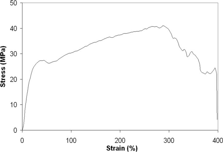
A representative stress-strain curve for electrospun PU-5-1 scaffolds is seen in Figure 7. Tensile test data reveal mechanical performance similar to many in vivo soft tissues. The average elastic modulus, ultimate tensile strength (UTS), and ultimate strain were 1.8 ± 0.0 MPa, 36.7 ± 9.9 MPa, 221.5 ± 95.1 %, respectively. These values fall between those of collagen and elastin34. This is relevant since these proteins are the dominant contributions to the mechanical properties of soft tissue. The elastic modulus, UTS and ultimate strain of PU-5-1 scaffolds could be adjusted in future formulations by altering the constituents of the copolymer and/or the fiber architecture. Alignment of fibers along different axes has been shown to induce changes in mechanical properties of an electrospun scaffold35. Future studies will modulate scaffold mechanical properties through control of fiber alignment.
Figure 7.
Representative stress-strain curve for electrospun PU-5-1.
Conclusion
A biodegradable, linear, segmented block polyurethane copolymer was designed specifically for preparing scaffolds via melt electrospinning. Polycaprolactone diol, 1,4-butane diisocyanate, and 1,4-butanediol in a 1/4/3 molar ratio and Mw of about 40 kDa (PU-5) yielded a useful polymer for this processing method. Extracting DBTDL catalyst resulted in a nontoxic polymer suitable for tissue engineering applications. The resulting nontoxic scaffold is composed of smooth, robust fibers lacking beads and with mechanical properties comparable to many native tissues. This polymer is worth pursuing in future investigations on scaffold alignment and its effect on cell and extracellular matrix alignment with the ultimate goal being tailoring the mechanical and biological properties of a tissue engineering scaffold.
Acknowledgments
The authors are grateful to Dr. Weiping Zhang for assistance with the cytotoxicity study. This study was supported by University of Washington Engineered Biomaterials (UWEB) and NIH RO1 HD038554. In addition, A. Karchin was funded through the NIH Engineered Biomaterials Training Program (EBTP).
Footnotes
Author Disclosure Statement
No competing financial interests exist.
References
- 1.Bhardwaj N, Kundu SC. Electrospinning: a fascinating fiber fabrication technique. Biotechnol Adv. 2010;28(3):325–47. doi: 10.1016/j.biotechadv.2010.01.004. [DOI] [PubMed] [Google Scholar]
- 2.Larrondo L, Manley RS. Electrostatic fiber spinning from melts I. Experimental observations on fiber formation and properties. Journal of Polymer Science. 1981;19:909–920. [Google Scholar]
- 3.Larrondo L, Manley RS. Electrostatic fiber spinning from melts II. Examination of the Flow Field in an Electrically Driven Jet. Journal of Polymer Science. 1981;19:921–932. [Google Scholar]
- 4.Larrondo L, Manley RS. Electrostatic fiber spinning from melts III. Electrostatic Deformation of Pendant Drop of Polymer Melt. Journal of Polymer Science. 1981;19:933–940. [Google Scholar]
- 5.Kim J-S, Lee DS. Thermal properties of electrospun polyesters. Polymer Journal. 2000;32(7):616–618. [Google Scholar]
- 6.Zhou H, Green TB, Joo YL. The thermal effects on electrospinning of polylactic acid melts. Polymer. 2006;47:7497–7505. [Google Scholar]
- 7.Dalton PD, Lleixa Calvet J, Mourran A, Klee D, Moller M. Melt electrospinning of poly-(ethylene glycol-block-epsilon-caprolactone). Biotechnol J. 2006;1(9):998–1006. doi: 10.1002/biot.200600064. [DOI] [PubMed] [Google Scholar]
- 8.Dalton PD, Klinkhammer K, Salber J, Klee D, Moller M. Direct in vitro electrospinning with polymer melts. Biomacromolecules. 2006;7(3):686–90. doi: 10.1021/bm050777q. [DOI] [PubMed] [Google Scholar]
- 9.Rockwood DN, Woodhouse KA, Fromstein JD, Chase DB, Rabolt JF. Characterization of biodegradable polyurethane microfibers for tissue engineering. J Biomater Sci Polym Ed. 2007;18(6):743–58. doi: 10.1163/156856207781034115. [DOI] [PubMed] [Google Scholar]
- 10.Heijkants RG, van Calck RV, van Tienen TG, de Groot JH, Buma P, Pennings AJ, Veth RP, Schouten AJ. Uncatalyzed synthesis, thermal and mechanical properties of polyurethanes based on poly(epsilon-caprolactone) and 1,4-butane diisocyanate with uniform hard segment. Biomaterials. 2005;26(20):4219–28. doi: 10.1016/j.biomaterials.2004.11.005. [DOI] [PubMed] [Google Scholar]
- 11.Xie R, Bhattacharjee D, Argyropoulos J. Polyurethane Elastomers Based on 1,3 and 1,4-Bis(Isocyanatomethyl)cyclohexane. Journal of Applied Polymer Science. 2009;113:839–848. [Google Scholar]
- 12.Santerre JP, Woodhouse K, Laroche G, Labow RS. Understanding the biodegradation of polyurethanes: from classical implants to tissue engineering materials. Biomaterials. 2005;26(35):7457–70. doi: 10.1016/j.biomaterials.2005.05.079. [DOI] [PubMed] [Google Scholar]
- 13.Marcos-Fernandez A, Abraham GA, Valentin JL, San Roman J. Synthesis and characterization of biodegradable non-toxic poly(ester-urethane-urea)s based on poly(epsilon-caprolactone) and amino acid derivatives. Polymer. 2006;47(3):785–798. [Google Scholar]
- 14.Freshney RI. Culture of animal cells : a manual of basic technique and specialized applications. 6th ed. John Wiley & Sons; Hoboken, N.J.: 2010. [Google Scholar]
- 15.Bruin P, Veenstra GJ, Nijenhuis AJ, Pennings AJ. Design and Synthesis of Biodegradable Poly(Ester-Urethane) Elastomer Networks Composed of Non-Toxic Building-Blocks. Makromolekulare Chemie-Rapid Communications. 1988;9(8):589–594. [Google Scholar]
- 16.Skarja GA, Woodhouse KA. Synthesis and characterization of degradable polyurethane elastomers containing and amino acid-based chain extender. J Biomater Sci Polym Ed. 1998;9(3):271–295. doi: 10.1163/156856298x00659. [DOI] [PubMed] [Google Scholar]
- 17.Skarja GA, Woodhouse KA. In vitro degradation and erosion of degradable, segmented polyurethanes containing an amino acid-based chain extender. J Biomater Sci Polym Ed. 2001;12(8):851–873. doi: 10.1163/156856201753113060. [DOI] [PubMed] [Google Scholar]
- 18.Benjamin M, Evans EJ, Copp L. The histology of tendon attachments to bone in man. J Anat. 1986;149:89–100. [PMC free article] [PubMed] [Google Scholar]
- 19.Simonovsky FI, Wu Y, Golledge SL, Ratner BD, Horbett TA. Poly(ether urethane)s incorporating long alkyl side-chains with terminal carboxyl groups as fatty acid mimics: synthesis, structural characterization and protein adsorption. J Biomater Sci Polym Ed. 2005;16(12):1463–1483. doi: 10.1163/156856205774576691. [DOI] [PubMed] [Google Scholar]
- 20.Wu Y, Simonovsky FI, Ratner BD, Horbett TA. The role of adsorbed fibrinogen in platelet adhesion to polyurethane surfaces: a comparison of surface hydrophobicity, protein adsorption, monoclonal antibody binding, and platelet adhesion. J Biomed Mater Res A. 2005;74(4):722–738. doi: 10.1002/jbm.a.30381. [DOI] [PubMed] [Google Scholar]
- 21.Kafengaus AP, Kazarinova NV, Nepyshnevsky VM, Simonovsky FI, Gladkaya MA. Method for producing of polyurethane solutions. 1978 SU Patent 640547.
- 22.Simonovsky F, Zaplatin A, Samigullin F, Khudyak E. Method for producing of polyetherurethanes in solution. 1989 Soviet Union Patent 1746688.
- 23.Mitchell SB, Sanders JE. A unique device for controlled electrospinning. J Biomed Mater Res A. 2006;78(1):110–120. doi: 10.1002/jbm.a.30673. [DOI] [PubMed] [Google Scholar]
- 24.Zong XH, Kim K, Fang DF, Ran SF, Hsiao BS, Chu B. Structure and process relationship of electrospun bioabsorbable nanofiber membranes. Polymer. 2002;43(16):4403–4412. [Google Scholar]
- 25.us P. Biological reactivity tests, In Vitro <87>. Rockville, MD, USA.: 2000. p. 1832. [Google Scholar]
- 26.Neumann T, Hauschka SD, Sanders JE. Tissue engineering of skeletal muscle using polymer fiber arrays. Tissue Eng. 2003;9(5):995–1003. doi: 10.1089/107632703322495637. [DOI] [PubMed] [Google Scholar]
- 27.Ratner B, Hoffmann A, Schoen F, Lemons J, editors. Biomaterials Science: An Introduction to Materials in Medicine. Second ed. Elsevier Academic Press; London: 2004. p. 879. [Google Scholar]
- 28.Yamamoto N, Nakayama A, Oshima M, Kawasaki N. Aiba S-i. Enzymatic hydrolysis of lysine diisocyanate based polyurethanes and segmented polyurethane ureas by various proteases. Reactive and Functional Polymers. 2007;67(11):1338–1345. [Google Scholar]
- 29.Duthon VB, Barea C, Abrassart S, Fasel JH, Fritschy D, Ménétrey J. Anatomy of the anterior cruciate ligament. Knee Surgery, Sports Traumatology, Arthroscopy. 2005;14(3):204–213. doi: 10.1007/s00167-005-0679-9. [DOI] [PubMed] [Google Scholar]
- 30.Tan S-H, Inai R, Kotaki M, Ramakrishna S. Systemic parameter study for ultra-fine fiber fabrication via electrospinning process. Polymer. 2005;46:6128–6134. [Google Scholar]
- 31.Gupta P, Elkins C, Long TE, Wilkes GL. Electrospinning of linear homopolymers of poly(methyl methacrylate): exploring relationships between fiber formation, viscosity, molecular weight and concentration in a good solvent. Polymer. 2005;46(13):4799–4810. [Google Scholar]
- 32.Dalton PD, Grafahrend D, Klinkhammer K, Klee D, Moller M. Electrospinning of polymer melts: Phenomenological observations. Polymer. 2007;48:6823–6833. [Google Scholar]
- 33.Johnson J, Ghosh A, Lannutti J. Microstructure-property relationships in a tissue-engineering scaffold. J Appl Polym Sci. 2007;104(5):2919–2927. [Google Scholar]
- 34.Bronzio J, editor. The biomedical engineering handbook. Vol. 2. CRC Press LLC; Boca Raton, FL: 1999. p. 1656. [Google Scholar]
- 35.Ayres CE, Bowlin GL, Pizinger R, Taylor LT, Keen CA, Simpson DG. Incremental changes in anisotropy induce incremental changes in the material properties of electrospun scaffolds. Acta Biomater. 2007;3(5):651–661. doi: 10.1016/j.actbio.2007.02.010. [DOI] [PMC free article] [PubMed] [Google Scholar]


