Abstract
Objective
Percutaneous cochlear implantation (PCI) surgery uses patient-specific customized microstereotactic frames to achieve a single drill-pass from the lateral skull to the cochlea avoiding vital anatomy. We demonstrate the use of a specific microstereotactic frame, called a “Microtable”, to perform PCI surgery on cadaveric temporal-bone specimens.
Study Design
Feasibility study using cadaveric temporal-bones.
Subjects and Methods
PCI drilling was performed on six cadaveric temporal-bone specimens. The main steps involved were (1) placing three bone-implanted markers surrounding the ear, (2) obtaining a CT scan, (3) planning a safe surgical path to the cochlea avoiding vital anatomy, (4) constructing a microstereotactic frame to constrain the drill to the planned path, and (5) affixing the frame to the markers and using it to drill to the cochlea. The specimens were CT scanned after drilling to show the achieved path. Deviation of the drilled path from the desired path was computed, and the closest distance of the mid- axis of the drilled path from critical structures was measured.
Results
In all six specimens, we drilled successfully to the cochlea preserving the facial nerve and ossicles. In 4/6 specimens, the chorda tympani was preserved, and in 2/6 specimens, it was sacrificed. The mean ± standard deviation error at the target was found to be 0.31±0.10 mm. The closest distances of the mid-axis of the drilled path to structures were 1.28±0.17 mm to facial nerve, 1.31±0.36 mm to chorda tympani, and 1.59±0.43 mm to ossicles.
Conclusion
In a cadaveric model, PCI drilling is safe and effective.
INTRODUCTION
Percutaneous cochlear implantation (PCI) involves drilling a linear path from the lateral skull to the cochlea through the facial recess. PCI can be performed using a customized microstereotactic frame that constrains the drill to the desired path. We have shown in our previous in vitro1,2 and in vivo3,4 validation studies that it is possible to choose a safe linear drill path for PCI and to construct a customized microstereotactic frame that guides the drill to the cochlea without causing risk to the facial nerve.
The main steps in PCI involves bone-implanting at least three fiducial markers surrounding the mastoid, acquiring a CT scan, planning a safe trajectory in the CT scan relative to the location of the fiducial markers, designing and constructing a customized microstereotactic frame that mounts on the fiducial markers and achieves the specified trajectory, and using the frame to drill to the cochlea. Our prior studies involved validation of the PCI technique to make sure that a drill passing through the frame will target the cochlea without risk to the facial nerve1–4.
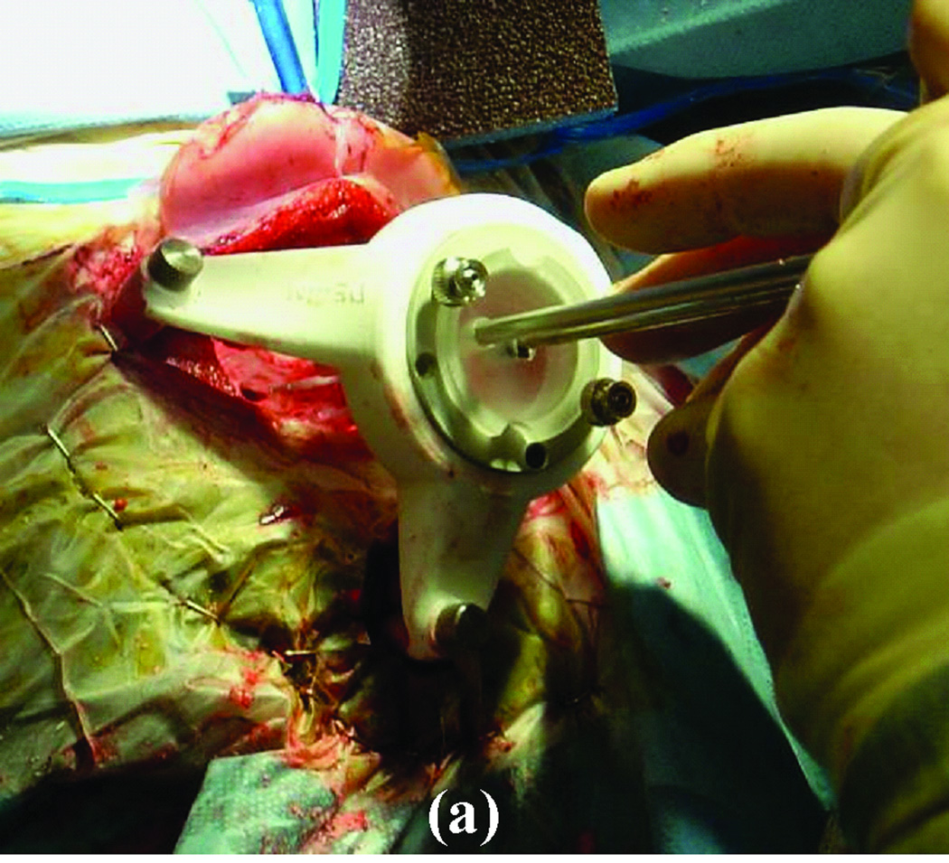
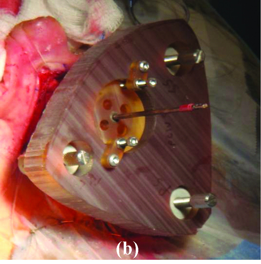
For this application, we have tested two microstereotactic frames (Figure 1)—the commercially available STarFix™ microTargeting™ Platform (FHC, Inc., Bowdoin, ME) and the recently developed microstereotactic table (which we refer to as a “microtable”)—both of which achieve the submillimetric accuracy necessary for PCI. The Starfix platform is an FDA-approved microstereotactic frame for deep-brain stimulation surgeries. It is manufactured using rapid-prototyping technology at a centralized facility. As a result, there is a two-day delay in getting the microstereotactic frame ready for the surgery after obtaining the CT scan. This delay necessitates implanting markers on patients in the clinic at least two days prior to the surgery, which is inconvenient for both patients and surgeons.
Figure 1. Clinical validation of the PCI technique using a customized microstereotactic frame.
(a) Starfix platform. (b) Microtable.
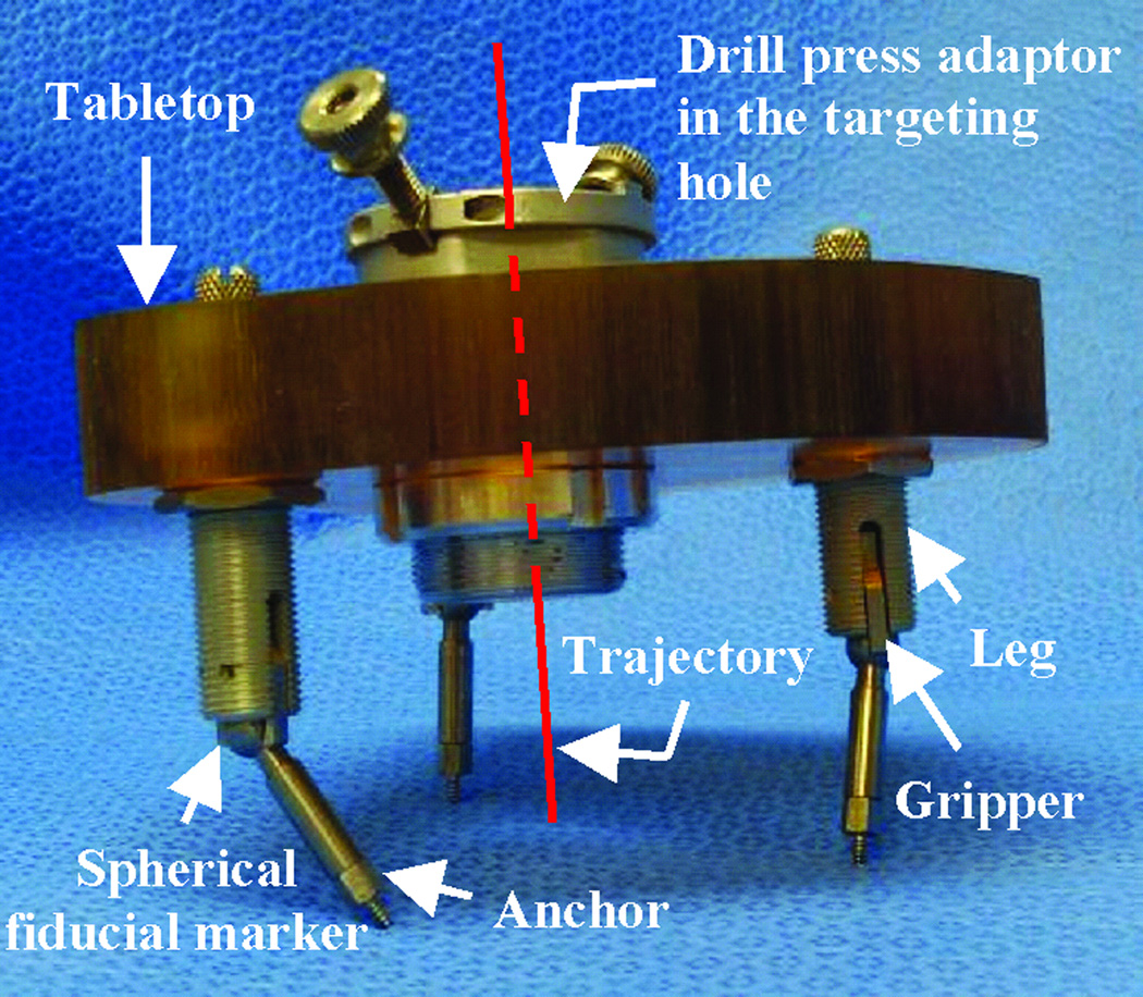
To avoid the manufacturing delay, we developed the microtable as an alternate microstereotactic frame that can be constructed onsite within a few minutes2. The microtable consists of a tabletop supported by three legs that mount on the bone-implanted markers such that the tabletop is perpendicular to the desired trajectory (Figure 2). The tabletop has four holes, three of which are used to connect to three legs and a fourth that serves as a targeting hole that determines the trajectory. The three holes for the legs are countersunk based on the anatomy of the patient and the desired trajectory. The targeting hole is always designed such that the top of the countersink is 75 mm from the cochlea. The tabletop can be manufactured in less than four minutes using a standard computer-numeric-control (CNC) machine. The in vitro targeting accuracy of microtable has been shown to be 0.37 ± 0.18 mm2, which is similar to the accuracy of the Starfix platform (0.45 ± 0.15 mm)5.
Figure 2. Microtable design.
The tabletop has three holes for legs that mount on markers and a targeting hole for the trajectory.
We have previously reported on the use of the microtable for an application similar to PCI, namely percutaneous access to the petrous apex6. The drilling mechanism we used in that recent report has been improved to achieve better accuracy. In this report, we present the results of PCI drilling in cadaveric temporal-bone specimens to target the cochlea. We follow the same procedure we propose to use for the clinical implementation of PCI.
METHODS
Cadaveric temporal-bone specimens were used. Therefore, IRB approval was not necessary for this study.
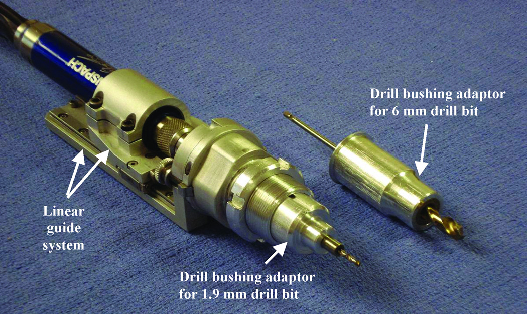
We designed a drill press for this study to advance the drill linearly along the path constrained by the microtable. Based on our previous drilling experience6 and guidelines from the Machinery’s Handbook7, we designed a new drill press (Figure 3) that consists of a linear guide system that controls the straight travel of the drill to a specific distance and a drill bushing adaptor that is used to restrict the movement of the drill bit during drilling. We chose to use a traditional “twist” drill bit for our application because otologic drill bits, which are spherical in shape with side-cutting flutes, are not ideal for forward drilling. For each specimen, we begin drilling with a 6 mm diameter drill bit and then switch to a 1.9 mm diameter drill bit for the last 20 mm to the target, during which the facial recess is traversed. The linear guide system of the drill and drill-tip bushing adaptors are designed such that we drill the exact desired distance and cannot physically override the system to drill farther down the path. The desired distances are accurately preset using a FARO Gage Plus coordinate measuring machine (Faro Technologies Inc., Lake Mary, FL). The 6 mm beginning hole can be used to provide irrigation during the deeper drilling. The 1.9 mm hole size to the cochlea will provide sufficient room for electrode implantation using a customized insertion tool8,9.
Figure 3. Drill press system.
The linear guide system controls the advancement of the drill, and the drill bushing adaptor controls the movement of the drill bit.
For the current study, we followed the same procedure that we would potentially follow for clinical implementation. The procedure involves the following steps. (Note that except for steps 1 and 2, which are done prior to the surgery, all the steps are performed in the operating room.)
Acquisition of pre-operative CT scan: A clinically-applicable temporal bone CT scan is acquired. For this current study, we use a Philips Mx8000 IDT 16 (16-slice acquisition) CT scanner that can provide a pixel size of 0.25-by-0.25 mm and slice thickness of 0.8 mm with 0.4 mm overlap.
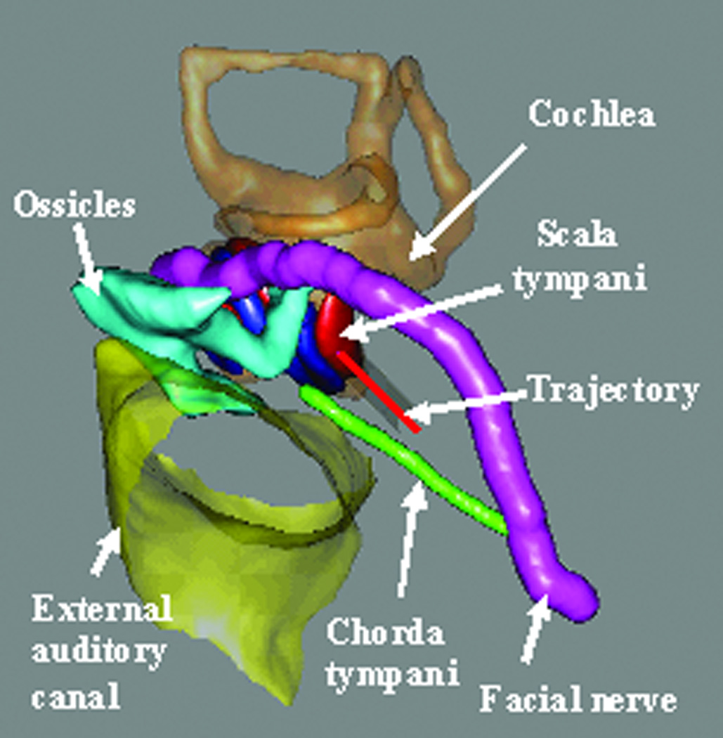
Pre-operative trajectory planning: A safe drill trajectory is automatically planned using the pre-operative CT scan. To achieve this automatic planning, the significant structures around the target—namely the facial nerve, the chorda tympani, the cochlea, the labyrinth, the ossicles, and the external auditory canal—are automatically segmented using methods described previously by our group10,11. A drill trajectory is then automatically determined that targets the scala tympani avoiding the facial nerve12 (Figure 4). Segmentation followed by trajectory determination is completed in approximately three minutes using an Intel Xeon 2.4 GHz dual quad-core 64-bit machine with 10 GB RAM. The segmentation results and the trajectory are verified by the surgeon.
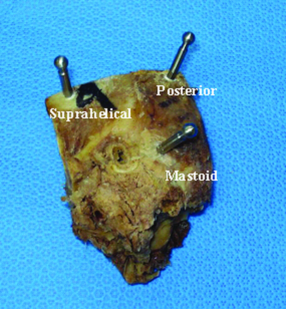
Implantation of fiducial markers: Markers are bone-implanted at three locations surrounding the target region—typically in the mastoid tip, the supra-helical region, and the region posterior to the sigmoid sinus (Figure 5). Each marker consists of an anchor that screws into the bone and an extension, at the tip of which is a spherical portion that serves as a fiducial (Figure 2). Using these spheres as fiducials, instead of the anchors themselves, provides higher accuracy2.
Acquisition of intra-operative CT scan: After the spherical fiducial markers are attached, an xCAT® ENT mobile CT scanner (Xoran Technologies, Ann Arbor, MI) is used to acquire a CT scan with a voxel size of 0.3 mm in all directions.
Intra-operative planning: The pre-operative and intra-operative CT scans of the patient are registered using a standard mutual-information method13, and the trajectory is transformed from the pre-operative scan to the intra-operative scan. Also, the centers of the spherical fiducial markers are automatically localized. This step takes approximately four minutes.
Design and fabrication of customized microstereotactic frame: The marker locations and the desired trajectory are used to design a customized microtable. The design involves determining the location and depths of four holes in the tabletop of the microtable and the lengths of the three legs that connect the tabletop to the markers. A custom Matlab (The Mathworks, Natick, MA) program automatically determines these values, creates a virtual model of the microtable, and generates the commands (in G-code) necessary to run the CNC milling machine for fabricating the tabletop. This program takes two or three seconds to run. The tabletop is then fabricated in less than four minutes from a blank of Ultem® (Quadrant Engineering Plastic Products, Reading, PA) using a CNC milling machine (Ameritech CNC, Broussard Enterprises, Inc., Santa Fe Springs, CA). Legs of lengths specified by the program are fitted into the three leg holes of the microtable, and a drill-press adaptor is attached to the targeting hole (Figure 2). A quality assurance check is performed on the parts of the microtable. Attachment of parts to the tabletop and quality assurance takes approximately two minutes.
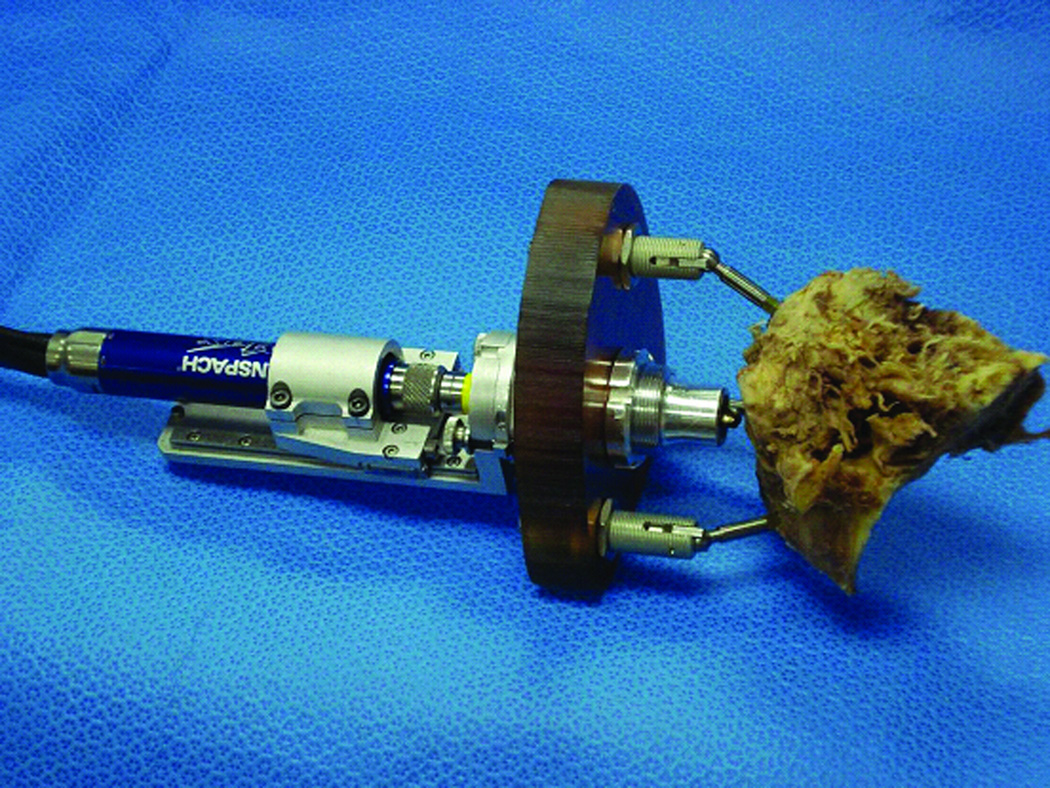
Attachment of frame and drilling: The microtable is attached to the markers by tightening the grippers, which attach to the spherical fiducial markers using thumbscrews (Figure 6). The drill bushing adaptor for the 6 mm drill bit is inserted into the drill press, and then the assembly is inserted into the targeting hole of the microtable. Thumbnuts are tightened to hold the assembly in place. Drilling is then performed along the constrained path until the stop is reached. For the initial 6 mm drill bit, the stop is set at 20 mm from the desired target. The drill press and the drill bushing adaptor are then removed from the drill press adaptor. The 6 mm diameter drill bit is replaced with a 1.9 mm diameter drill bit. The drill bushing adaptor for the 1.9 mm drill bit is inserted into the drill press and then the assembly is attached to the drill press adaptor as before. Drilling is again performed until the drill press stops at 75 mm—the depth of the cochlea.
Acquisition of post-operative CT scan for validation: To analyze the quality of the drilling, a post-operative CT scan is acquired using the xCAT CT scanner with the 1.9 mm drill bit in the drilled trajectory. The spherical fiducial markers are present in this scan and are used to register it to the intra-operative scan by means of a rigid-body point-based registration algorithm14. The planned trajectory in the intra-operative scan is transformed to the post-operative scan and the deviation of the drilled trajectory from the planned trajectory is determined. The post-operative scan is also registered using standard mutual information registration technique13 to the pre-operative scan, in which the critical structures have been automatically segmented (see Step 2). Applying this registration transformation, we transform the axis of the drilled path to the pre-operative scan and measure the closest distance of the drilled path to the critical structures.
Figure 4. Trajectory planning.
Significant structures are automatically segmented, and a drill trajectory that targets the scala tympani and avoids the facial nerve is determined.
Figure 5.
Locations of the three spherical fiducial markers.
Figure 6.
Microtable and drill press assembly attached to a cadaveric temporal bone specimen for PCI drilling.
RESULTS
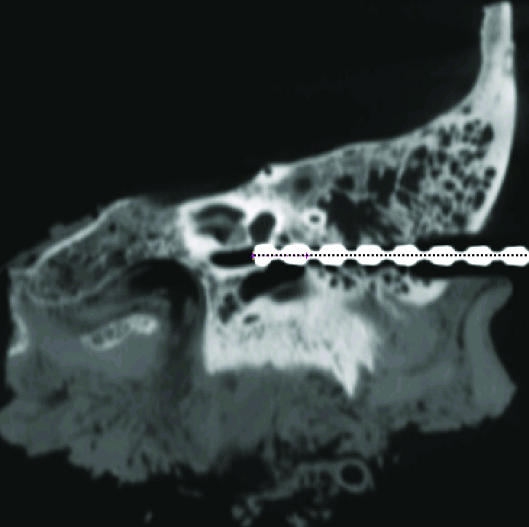
Six (n = 6) cadaveric temporal-bone specimens were used for this study, and the procedure described in the previous section was followed for each specimen. Both 6 mm and 1.9 mm diameter holes were drilled as specified. It took less than five minutes for drilling including both the 6 mm and 1.9 mm path. In all the specimens, the drill reached its target, i.e., the cochlea. Figure 7 shows the post-operative scan acquired with the 1.9 mm drill bit in the drilled hole.
Figure 7. Post-operative CT scan with the drill bit in the drilled hole.
The dotted line shows the desired trajectory.
To analyze the quality of the drilling, the mid-axis of the drilled path was localized in the post-operative CT scan and transformed to the intra-operative CT scan using the registration based on the spherical fiducial markers. The error of the system, defined as the deviation of the drilled path from the planned path, was computed at the target point and at a point 30 mm lateral from the target. The lateral point was chosen to assess any wandering of the drill tip shortly after impact with the lateral skull. Table 1 reports these error values for each specimen. The mean ± standard deviation error was 0.31 ± 0.10 mm at the target and 0.15 ± 0.09 mm at the lateral location.
Table 1.
Deviation of the drilled trajectory from the planned trajectory.
| Specimen | Ear | Deviation in millimeters | |
|---|---|---|---|
| At target | At lateral point | ||
| 1 | Left | 0.22 | 0.11 |
| 2 | Right | 0.22 | 0.12 |
| 3 | Left | 0.31 | 0.05 |
| 4 | Left | 0.45 | 0.32 |
| 5 | Right | 0.24 | 0.13 |
| 6 | Right | 0.41 | 0.19 |
| Mean ± SD | 0.31 ± 0.10 | 0.15 ± 0.09 | |
There was no contact between the drill and the facial nerve in any of the specimens. The shortest distance from the mid-axis of the drill to the facial nerve, chorda tympani, and ossicles were computed. Table 2 reports these distances for each specimen. The mean ± standard deviation of the closest distance was 1.28 ± 0.17 mm to the facial nerve, 1.31 ± 0.36 mm to the chorda tympani, and 1.59 ± 0.43mm to the ossicles. Margin distances between the surface of the 1.9 mm drill and the surface of a critical structure can be determined by subtracting the radius of the drill, which is 0.95 mm. Resulting negative numbers (Specimens 1 and 2, Chorda Tympani) indicate that the structure was sacrificed. The mean margin distance was 0.33 mm to the facial nerve, 0.36 mm to the chorda tympani, and 0.64 mm to the ossicles.
Table 2.
Closest distance of the mid-axis of the drilled trajectory to critical structures.
| Specimen | Distance to structures in millimeters | ||
|---|---|---|---|
| Facial Nerve |
Chorda Tympani |
Ossicles | |
| 1 | 1.06 | 0.83 | 1.56 |
| 2 | 1.34 | 0.88 | 1.34 |
| 3 | 1.23 | 1.60 | 1.35 |
| 4 | 1.50 | 1.53 | 1.40 |
| 5 | 1.40 | 1.65 | 2.45 |
| 6 | 1.12 | 1.34 | 1.45 |
| Mean ± SD | 1.28 ± 0.17 | 1.31 ± 0.36 | 1.59 ± 0.43 |
DISCUSSION
In a cadaveric model, we have demonstrated drilling for a PCI procedure as guided by customized microstereotactic frames. Drilling was performed on six (n = 6) cadaveric temporal bone specimens. The target was achieved without damage to vital anatomy. The facial nerve and ossicles were preserved in all six specimens with satisfactory distance between the drill and the structure. The chorda tympani was preserved in four specimens and sacrificed during planning and drilling in two specimens.
The achieved drilled path was close to the planned path with a deviation of 0.31 ± 0.10 mm at the target. This accuracy is dependent on the rigidity of the fiducial system relative to the patient’s head and the microtable. If the system is rigid, the image to physical registration will result in lower error at the target15. The anchors are bone-implanted enabling rigid attachment of the microstereotactic frame to the skull. Spherical fiducial markers are attached to the anchors, and the microtable is rigidly attached to the spherical fiducial markers. With this rigid system, the targeting accuracy of the microtable at the cochlea has been shown to be 0.37 ± 0.18 mm via phantom studies2. The current results of drilling, 0.31 ± 0.10 mm at the cochlea, are comparable to this prior work, showing that our drill system does not add significant error to the system.
The microtable has been clinically validated for accessing the cochlea4. With the success of PCI drilling shown in this study, we are in a position to begin PCI drilling in vivo. The procedure for this in vivo PCI drilling would be the same as that mentioned in the METHODS section with the only difference being that the microtable must be sterilized after fabrication (Step 6) and before attachment to the markers (Step 7). Immediately after fabrication, the microtable will be transported to the sub-sterile room near the operating room for sterilization. Approximate time to sterilize via steam is 15 minutes. Once sterilized, the microtable will be made available to the surgeon with total time from end of intraoperative CT scan to beginning of drilling of 30 minutes.
For the proposed technique, a CNC machine is required. The one utilized in our laboratory costs approximately $25,000. We are in the process of building a miniaturized version that can be located in the operating theater that would cost approximately $15,000. This initial capital expense may be offset by the time savings afforded by the new technique, which we estimate to be consistently performed in less than 60 minutes. This is a significant time savings over reports of traditional cochlear implantation16,17.
We anticipate performing PCI drilling in an incremental fashion to ensure safety to patients following which we will utilize a customized insertion tool8,9 to allow electrode insertion via the PCI drilled path. Our next step is drilling the lateral part of the path stopping well short of the facial recess following which an intra-operative CT scan will be acquired to confirm the accuracy of the achieved path. With successful lateral drilling, we will begin drilling through the facial recess with facial nerve monitoring. While this PCI approach seems radical, it is based on sound engineering concepts and data demonstrating submillimetric accuracy.
Acknowledgement
The project described was supported by Award Number R01DC008408 from the National Institute on Deafness and Other Communication Disorders. The content is solely the responsibility of the authors and does not necessarily represent the official views of the National Institute on Deafness and Other Communication Disorders or the National Institutes of Health.
Footnotes
The results were presented at the AAO-HNSF meeting in San Diego, CA on October 5, 2009.
Contributor Information
Ramya Balachandran, Department of Otolaryngology, Vanderbilt University Medical Center, 7209 Medical Center East, South Tower, 1215 21st Avenue South, MCE, Nashville, TN 37232, ramya.balachandran@vanderbilt.edu, Phone: 615-322-5550, Fax: 615-936-5515.
Jason E Mitchell, Department of Mechanical Engineering, Vanderbilt University, Nashville, TN.
Grégoire Blachon, Department of Electrical Engineering and Computer Science, Vanderbilt University, Nashville, TN
Jack H. Noble, Department of Electrical Engineering and Computer Science, Vanderbilt University, Nashville, TN
Benoit M. Dawant, Department of Electrical Engineering and Computer Science, Vanderbilt University, Nashville, TN.
J Michael Fitzpatrick, Department of Electrical Engineering and Computer Science, Vanderbilt University, Nashville, TN.
Robert F. Labadie, Department of Otolaryngology-Head and Neck Surgery, Vanderbilt University Medical Center, Nashville, TN.
REFERENCES
- 1.Warren FM, Balachandran R, Fitzpatrick JM, et al. Percutaneous cochlear access using bone-mounted, customized drill guides: demonstration of concept in vitro. Otol Neurotol. 2007;28:325–329. doi: 10.1097/01.mao.0000253287.86737.2e. [DOI] [PubMed] [Google Scholar]
- 2.Labadie RF, Mitchell J, Balachandran R, et al. Customized, rapid-production microstereotactic table for surgical targeting: description of concept and in vitro validation. Int J CARS. 2009;4:273–280. doi: 10.1007/s11548-009-0292-3. [DOI] [PMC free article] [PubMed] [Google Scholar]
- 3.Labadie RF, Noble JH, Dawant BM, et al. Clinical validation of percutaneous cochlear implant surgery: initial report. Laryngoscope. 2008;118:1031–1039. doi: 10.1097/MLG.0b013e31816b309e. [DOI] [PMC free article] [PubMed] [Google Scholar]
- 4.Labadie RF, Balachandran R, Mitchell J, et al. Clinical Validation Study of Percutaneous Cochlear Access Using Patient Customized Micro-Stereotactic Frames. Otol Neurotol in press. doi: 10.1097/MAO.0b013e3181c2f81a. [DOI] [PMC free article] [PubMed] [Google Scholar]
- 5.Balachandran R, Mitchell JE, Dawant BM, et al. Accuracy evaluation of microTargeting Platforms for deep-brain stimulation using virtual targets. IEEE Trans Biomed Eng. 2009;56:37–44. doi: 10.1109/TBME.2008.2002110. [DOI] [PMC free article] [PubMed] [Google Scholar]
- 6.Wanna GB, Balachandran R, Majdani O, et al. Percutaneous access to the petrous apex in vitro using customized micro-stereotactic frames based on image-guided surgical technology. Acta Otolaryngol. 2009:1–6. [PMC free article] [PubMed] [Google Scholar]
- 7.Oberg E, Jones F, Horton H. Machinery's handbook. New York: Industrial Press Inc.; 1996. [Google Scholar]
- 8.Majdani O, Schurzig D, Hussong A, et al. Force measurement of insertion of cochlear implant electrode arrays in vitro: comparison of surgeon to automated insertion tool. Acta Otolaryngol. 2009:1–6. doi: 10.3109/00016480902998281. [DOI] [PMC free article] [PubMed] [Google Scholar]
- 9.Schurzig D, Labadie RF, Webster RJ. Design of a Robotic Insertion Tool for Cochlear Implantation with Nanometer-Precision and milli-Newton Force Sensing. IEEE Trans Mechatronics in submission [Google Scholar]
- 10.Noble JH, Warren FM, Labadie RF, et al. Automatic segmentation of the facial nerve and chorda tympani in CT images using spatially dependent feature values. Med Phys. 2008;35:5375–5384. doi: 10.1118/1.3005479. [DOI] [PMC free article] [PubMed] [Google Scholar]
- 11.Noble JH, Dawant BM, Warren FM, et al. Automatic identification and 3D rendering of temporal bone anatomy. Otol Neurotol. 2009;30:436–442. doi: 10.1097/MAO.0b013e31819e61ed. [DOI] [PMC free article] [PubMed] [Google Scholar]
- 12.Noble JH, Warren FM, Labadie RF, et al. Determination of drill paths for percutaneous cochlear access accounting for target positioning error. Progress in Biomedical Optics and Imaging - Proceedings of SPIE. 2007:650925.1–650925.10. [Google Scholar]
- 13.Maes F, Collignon A, Vandermeulen D, et al. Multimodality image registration by maximization of mutual information. IEEE Transactions on Medical Imaging. 1997;16:187–198. doi: 10.1109/42.563664. [DOI] [PubMed] [Google Scholar]
- 14.Fitzpatrick JM, Hill DLG, Maurer CR. Registration. In: Sonka M, Fitzpatrick JM, editors. Handbook of Medical Imaging Volume 2 Medical Image Processing and Analysis. SPIE--The International Society for Optical Engineering; 2000. [Google Scholar]
- 15.Fitzpatrick JM, West JB. The distribution of target registration error in rigid-body point-based registration. IEEE Trans Med Imaging. 2001;20:917–27. doi: 10.1109/42.952729. [DOI] [PubMed] [Google Scholar]
- 16.Majdani O, Schuman TA, Haynes DS, et al. Time of Cochlear Implant Surgery in Academic Settings. Otolaryngology-Head and Neck Surgery. doi: 10.1016/j.otohns.2009.10.025. (in press). [DOI] [PMC free article] [PubMed] [Google Scholar]
- 17.Postelmans JT, Grolman W, Tange RA, et al. Comparison of two approached to the surgical management of cochlear implantation. Laryngoscope. 2009;119(8):1571–1578. doi: 10.1002/lary.20487. [DOI] [PubMed] [Google Scholar]


