

Abstract
Sutureless anastomosis devices are designed to reduce surgical time and difficulty, which may lead to quicker and less invasive cardiovascular anastomosis. The implant utilizes a barb-and-seat compression fitting composed of one male and two female components. The implant body is resorbable and capable of eluting heparin. Custom robotic deposition equipment was designed in order to fabricate the implants from a self-curing silk solution. Curing did not require deleterious processing steps but devices demonstrated high crush resistance, retention strength, and leak resistance. Radial crush resistance is in the range of metal vascular implants. Insertion force and retention strength of the anastomosis was dependent on fit sizing of the male and female components and subsequent vessel wall compression. Anastomotic burst strength was dependent on the amount of vessel wall compression, and capable of maintaining higher than physiological pressures. In initial screening using a porcine implant, the devices remained intact for 28 days (the length of study). Histological sections revealed cellular infiltration within the laminar structure of the male component, as well as at the interface between the male and female components. Initial degradation and absorption of the implant wall were observed. The speed per anastomosis using this new device was much faster than current systems, providing significant clinical improvement.
Keywords: silk, sutureless anastomosis, resorbable implant, drug delivery, bio-ink
INTRODUCTION
Manual suturing is the current gold standard for generating vascular anastomoses. Reconstitution of blood supply via vessel anastomosis remains a technically challenging and time consuming procedure with a steep learning curve for surgeons. Suturing errors such as uneven spacing, inversion of suture walls, and misalignment of the vessel intima can lead to anastomotic leaks, thrombosis, prolonged hospital stays and death.1,2 These and other factors have contributed to the persistent failure rates in 2–6% of cases, potential loss of reconstruction, and elevated health care costs.3,4 There is increasing demand for an easy, time saving, less damaging but reliable procedure to form vascular anastomoses. This is particularly crucial in trauma, cardiac surgery, and organ transplant surgery where patient survival is dependent on clamp time or warm ischemia time. By decreasing the level of technical dexterity required for anastomosis, pathways to less invasive tool and robotic facilitated anastomosis may become available. Furthermore, development of anastomosis devices which do not require highly skilled hands or lengthy surgical times will allow the possibility of temporary peripheral vessel bypass by minimally trained respondents in times of emergency such as direct combat casualty care.
A variety of vascular anastomosis mechanisms and devices have been pursued.5 Each anastomosis mechanism imparts varying levels of security and implantation difficulty. The average reported anastomosis time for these devices range from 14 to 100 minutes and require the use of specialized tools and a high level of dexterity. Devices such as microclips,6 ring staplers,7 and magnets8 have been used to improve sutureless anastomosis but are composed of non-degradable materials. Permanent vascular implants can induce chronic trauma and raises concerns for growing children or adolescents suffering from congenital disease or traumatic vascular injury.9 For these reasons, a gamut bioresorbable strategies are being developed for vascular implants.10,11 Current experimental bioresorbable devices exhibit relatively weak anastomotic pull out strength compared to permanent alternatives.12
The goal of the present study was to develop a fully resorbable, drug-eluting, sutureless anastomosis device for small to large diameter vessels in order to decrease complexity and ischemic time in vascular reconstructive surgical procedures. Additionally, the device was to be fabricated using a programmable rapid prototyping (RP) technique which enables the future possibility of patient specific treatment via inclusion of custom biologicals or programmed device dimensions if required. This device is formed from a silk protein blend, which does not require deleterious curing mechanisms, and can handle high pressures (2,800 mmHg) and flow rates once completed. Vascular anastomosis is simplified by providing a quick and feasible mechanical union without the need for specialized proprietary tools, piercing of vessel tissue, or tying of knots. The components fit concentrically within and around the vessel, which allows the device to align and complete the anastomosis procedure with single sliding motion.
MATERIALS AND METHODS
Preparation of Aqueous Silk-Glycerol Bio-ink Solution
Aqueous silk fibroin solutions were prepared following published procedures.13 Aqueous fibroin solutions were blended with 99% (w/v) glycerol MW 92.09 (Sigma-Aldrich Corp. St. Louis, MO, US), as previously described,14 to produce blends of 80:20 (dry w/w) silk:glycerol solution.
Fabrication of Device Components
The anastomosis device design was composed of two parts as described in Figure 1. Part 1 was an intraluminal coupler, which was a cylindrical tube with spherical barb tips at each end. A micro-stepped extrusion system was developed to robotically deposit layers of silk:glycerol bio-ink solution around Teflon-coated stainless steel rods (0.65 to 6 mm diameter) to fabricate the tubular film components [Figure 1]. The coating was allowed to dry to an insoluble state for 2 minutes between layers. Each coating produced a 40 μm thick tubular film layer and subsequent layers were deposited to achieve the target (150 to 300 μm) thickness. Lower concentrations of silk:glycerol can be used to generate thinner layers. The ellipsoid barb tips were produced in a separate step by dispensing 5 to 50 μl of silk:glycerol solution onto the previously coated rods. The final outer diameter of the barbs were equivalent to approximately 125% of the outer diameter of the coated rods [Figure 1(B)]. Part 2 [Figure 1(F)] was a tubular sheath clip fabricated by same technique to achieve thickness of 250 μm. Two or more opposing holes were excised from the sheath using a biopsy punch to form a recess seat. The holes were sized according the dimensions of the ellipsoid tip to be received. Couplers with an outer diameter of 3 mm (approximately 300 μm wall thickness) were used for in vitro studies to match the luminal diameter of porcine femoral vessels.
FIGURE 1.

Process flow of device fabrication: a) Coating of rods for clip and coupler components; b) Spherical barb tip deposition for coupler components; c) Removal of tubes from rods for clip components; d) Removal of tubes with spherical barbs from rods for couplers; e) Initial trimming of coupler components; f) Initial trimming of clip components from tube, and creation of seats using biopsy punch; g-i) Phase contrast demonstrating laminar structure and swelling of sidewall.
Surface Analysis
A scanning white-light interferometer (NewView 600, Zygo Co., Middlefield, CT, US) was used to measure topography, and profile. A 10X interferometric objective was used to scan the film in the Z-axis 5 μm below and above the surface plane to produce a 3D interferogram. Roughness (Ra) was measured along a 500 μm linear section on the luminal surface of 5 implants per time point (1, 30, or 180 days storage in sterile DI H20). Ra was expressed the difference in height between any measured point and the calculated mean sample height.
Swelling of Components
Five devices with 6 mm outer diameter were subjected to dehydration for seven days at ambient conditions, then rehydration in deionized water for 24 hours. Changes in diameter and wall thickness were measured using cylindrical class ZZ plug gauges and an electronic micrometer.
Mechanical Analysis
The coupler-vessel insertion force and anastomotic pull-out force was measured using uniaxial mechanical tester (model 3366, Instron Inc., Norwood, MA, US). The fully hydrated device components were removed from the aqueous storage vials and mechanical testing was performed in ambient conditions approximately 1 minute later. The components were assembled within this time frame for the various mechanical tests as described below. Insertion and pull-out tests were performed in triplicate at room temperature and repeated using four different assembly fitments which ranged in tightness. Tightness was measured as the amount of vessel wall compression produced between the outer diameter of the spherical bead tip of the coupler, and the inner diameter of the clip lumen. The four ranges were assembly fitments producing 25%, 50%, 75%, or 90% compression of the blood vessel wall. Forces were measured in Newtons. In the insertion force test the anastomosis clip over cadaver vessel segments was concentrically aligned over the fixed coupler and the construct was compressed in between two parallel plates in line with the load cell [Figure 3]. The construct was compressed at a rate of 1mm/min until the holes of tubular sleeve received the spherical barbs of the coupler thereby completing the assembly procedure [Figure 3(B)]. Pull-out force was measured by pulling the proximal and distal anastomosed vessel segments in opposing directions [Figure 3(C)]. Radial strength was assessed using a pressure chamber. A coupler was placed within a sealed latex sleeve. The external pressure was increased in steps until coupler collapse. Collapse pressure was measured in pounds per inch2.
FIGURE 3.

Mounting method for (a–b) mechanical testing of compression to insertion; (c) tensile testing procedure; (d) radial compressive resistance of the tubular component used in anastomosis device fabrication. Crush resistance of 5 different implant wall thickness are compared to femoral vein (F.V.) and artery (F.A.) and a clinically available metal self-expanding stent (MSES) (Boston Scientific Wallstent); (e) Effect of 50% vessel wall compression on insertion force and pull-out retention strength.
Analysis of Anastomotic Seal
Porcine femoral vessels from 6–9 month old 250 lb. Yorkshire pigs were ordered from Animal Technologies, Inc. (Tyler, TX, US). Anastomotic seal was evaluated using a peristaltic pump and polyethylene terephthalate (PET) tubing. Anastomosis was performed by securing couplers into the proximal and distal ends of the vessel segments. The flow loop was then completed with PET tubing [Figure 4(A)]. Phosphate buffered saline (PBS) was flowed through the flow loop, and PBS was used to fill the burst chamber which housed the assembled anastomosis device. Flow rate was increased by 4 mL·min−1 each second until anastomotic failure was reached. A butterfly valve placed inline distal to the anastomosis to restrict the flow and to increase the line pressure until anastomotic failure was reached. Experiments were performed in triplicate.
FIGURE 4.

(a) Bench top flow loop and burst chamber designed for this work; (b) maximum supported flow rate and burst pressure per compression fitting tightness; (c) Interferograms measuring implant luminal surface roughness after 1, 30, and 180 days of aqueous storage.
Heparin Release Kinetics
Heparin and Fluorescein conjugated Heparin was purchased from Invitrogen Life Technologies (Grand Island, NY, US). Coupler devices were soaked in fluorescein conjugated heparin solution (0.5mg/ml in deionized water) using two different techniques. Either the luminal surface of the couplers were coated with fluorescein conjugated heparin solution or the coupler devices were completely submerged into the solution for 24 hours [Figure 5(A)]. After equilibration for 24 hours, the couplers were rinsed with deionized water and secured between two segments of silicon tubing mounted in line with a standard perfusion system to mimic dynamic flow conditions for drug release [Figure 5(B)]. The devices were perfused at a rate of 2 ml/min for 1 hour and 1 ml/hr for 24 hours using deionized water. The perfused silk couplers were removed from the perfusion system and then dissolved in lithium bromide solution to quantify the remnant drug. The dissolved samples and standards (known amount of fluorescein conjugated heparin in silk/lithium bromide solution) were measured (at 495 nm excitation and 515 nm emission) using a plate reader (Molecular Device, LLC, model: SpectraMax M12, Sunnyvale, CA) and plotted in micro-grams. The error bars represent the standard deviation and n=5 per condition and time point.
FIGURE 5.
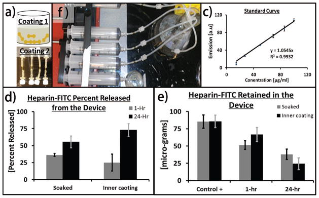
(a) Schematic describing the procedure of loading devices with Heprain (top) bulk loading via hydration in hepariniized solution (bottom) inner wall coating; (b) perfusion system used to perform the release studies; (c) standard curve; (d) total quantity of Heprain released from the devices over 24 hours time period; (e) amount of remant drug retained in the deivces at 0, 1, or 24 hours.
In Vivo Implantation
Implantations were conducted according to the recommendations of IACUC at an approved DLAM facility according to our IACUC approved protocol. Surgeries were performed on a 30 kg male Yorkshire pig. A 6–8 cm incision from the inguinal region down the medial aspect of the hind leg was performed to access the common femoral vein. The femoral vein was transected and the lumens were then flushed with dilute heparinized saline. Anastomosis was performed as described previously in Figure 2. The coupler had a wall thickness of 250 μm and the outer diameters of the coupler body and ellipsoid tips measured 3.5 mm and 4.75 mm, respectively, when fully hydrated. The coupler was inserted into a 3.5 to 4.5 mm femoral vein with approximately 600 μm wall thickness. The clips had an inner diameter of 5.15 mm which produced approximately 70.8% compression of the vessel wall. The seat diameters were 3 mm. No sutures were used to assist anastomosis. The incision was then closed. The anastomosis device was implanted in vivo into a porcine femoral vein, without long-term supplementation with antithrombotics or antiproliferatives. At the terminal time point of 4 weeks the pig had grown to 70 kg. The implant and vessel construct was then be prepped for histological analysis and stored in formalin. Euthasol IV (Pentobarbital 390 mg/ Phenytoin 50 mg), at 0.22 mL/kg, was administered intravenously immediately following these procedures.
FIGURE 2.

(a) Schematic of assembled components (b) cross-section view; (c–f) method of anastomosis, (c, d) first the clip was inserted over the vessel followed by (d, e) inserting the coupler into the vessel.(e, f) Finally, the clip is then slid toward the coupler and locked into place by aligning the seats over around the barbs.
Histological Staining
The vein/implant construct was bisected for embedding in paraffin. After embedding was complete, the blocks were further sectioned from the proximal to the distal end to produce six cross-section slides every 2 mm. The sections received one of six treatments, three of which were stained with H&E, trichrome, or Verhoeffs Elastic Stain. The remaining three were treated for immunohistochemistry (IHC). The IHC treatments were Factor VIII, CD31, or Smooth Muscle Actin.
RESULTS
Device Fabrication and Anastomosis Strategy
The robotic deposition RP technique facilitated consistent fabrication of the laminar film device from the silk solution. The device was designed based on the targeted blood vessel diameters, vessel wall thickness, and swelling ratio of the hydrated device. The anastomosis strategy uses three resorbable components; two identical tubular clip sheaths with two opposing holes and the third component is a tubular coupler terminating with ellipsoid barbs at each end. The holes in the clip act as a recessed seat for receiving the barbs of the coupler which subsequently forms the anastomotic mechanical union [Figure 2]. The anastomosed vessels are secured between the coupler and the two clips and upon restoration of blood flow, blood passes from the proximal vessel segment through the lumen of the silk implant and then into the distal vessel segment [Figure 2(B)].
The implant body produced from silk was stiff in the dry state yet progressively softened when hydrated. This property eases implantation and then allows the implant to exhibit softer properties after implantation, avoiding stress shielding and minimizing the risk of long-term chronic irritation. Unlike tyrosine-derived polycarbonate, salicylate, and magnesium alloys, hydration of this silk material swells slightly after hydration in physiological conditions [Figure 1(H,I)].15 The outer diameter and sidewall thickness of the coupler increased approximately 12% and 30%, respectively, after hydration. This property may confer more secure vessel fitment, in contrast to concerns with shrinking reported for polylactic acid implants.16
The design of this device was limited by the degree of flow resistance due to the thickness of the implant walls. The resistance to fluid flow and pressure change across the implant as a function of wall thickness was estimated by Poiseuille using the equations; R = 8ηL/(πr4) and ΔP = 8ηLQ/(πr4), respectively where R = resistance, L = implant length, η = viscosity, r = the implant luminal radius, ΔP = pressure change and Q = the volumetric flow rate. The resistance and pressure change are inversely proportional to the luminal radius raised to the fourth power, thus a small change in radius has a significant impact. Although the implants are not likely to experience pressures in the peak aortic range of 140 mmHg or 19kPa, we estimated the affect that this pressure would have on radial displacement using tensile mechanical analysis of the implant material. A stress of 25.6 ± 0.7 kPa resulted in a 2e−3 ± 7e−5 % uniaxial strain, or radial displacement of 3.2e−4 % considering Δr = Δx/2π, where Δx is the change in strain. These small radial displacements are not large enough to invalidate the estimations produced using Poiseuille’s equation for our purpose. The luminal diameter of the anastomosis device did not deform significantly under physiological pressures, thus we estimated that pressure drop due to the implant was mainly a result of the reduction in luminal cross-sectional area by the sidewalls of the device.
An implant wall thickness of 300 μm produced the maximum radial strength per unit pressure drop within the 4 mm vessel model, targeted for in vivo implantation, and produced similar results for smaller caliber vessels. Additionally, the implant wall thickness of 300 μm produced the highest radial strength to flow resistance ratio when estimated for average and peak physiological flows within the vessel model. These results supported the design of a 300 μm implant wall thickness for use in the porcine femoral vein.
Radial Strength
The functional design of the device compression fitting requires radial strength capable of maintaining radial tension at the coupler bead and clip seat interface. Radial crush resistance of the implant within a latex pressure chamber was dependent on wall thickness [Figure 3]. The maximum crush resistance of 4.48 psi was obtained from the couplers of approximately 300 μm wall thickness, which was nearly 45% higher than self-expanding metallic vascular implants. Further increases in the wall thickness marginally increased the crush pressure but would significantly increase flow resistance.
Assembly Force and Retention Strength
For assembly, the coupler outer diameter was matched to that of each blood vessel lumen, but mated with tubular clips of various internal diameters to achieve various compression strengths. The insertion force and retention strength were dependent on fit sizing of the male and female components and subsequent vessel wall compression [Figure 3]. The fitment pairing mechanically demonstrated the function of the directional barb-and-seat geometry of the implant assembly which was designed to require more force to disassemble compared to initial assembly force. The 90% compressed vessel wall required the highest insertion force and may severely damage the vessel. The 50% vessel compression yielded similar pull-out force compared to 75% compression, however, the insertion force for the later was significantly higher. A full table of insertion force and retention strength per fitment is provided in Table 1.
Table 1.
Effect of vessel wall compression on insertion force and pull-out retention strength.
| Wall Compression [%] | Insertion Force [N]a) | Retention Strength [N] |
|---|---|---|
| 25 | 0.36±0.21 | 0.48±0.10 |
| 50 | 1.2±0.06 | 4.4±0.49 |
| 75 | 3.9±0.85 | 4.7±0.76 |
| 90 | 3.3±0.48 | 11.6±1.9 |
Newtons
Peak Pressure Leak Resistance
The stability of the anastomotic seal was also dependent on the percent compression of the vessel wall [Figure 4]. The luminal cross-sectional area of the coupler was not changed in order to preserve consistent flow resistance. At the lower vessel compression (approximately 25%) the failure occurred due to slippage of the coupler past the seat, while at 50% compression and above the mechanism of failure was tearing of the seat of the external clip. Although all compression settings failed at pressures greater than average physiologically relevant pressure, the 25% compression fitting demonstrated the potential to fail at reported peak physiological pressures.17,18 A minimum wall compression greater than 25%, such as 50%, would be recommended to confidently support peak pressures as well as resist failure due to longitudinal strains physiologically relevant to a mobile animal.
Anti-thrombotic Drug Elution
We coated the luminal surfaces with heparinized-silk or hydrated the devices with heparinized solution and performed the release kinetics of the same drug for up to 24 hours in vitro. The hydrated heparin-loaded devices rapidly released most of the drug, while the dry luminally-coated couplers exhibited delayed release [Figure 5]. This delay in release was likely due to the absorption of the drug during the drying process of the lumen coating. Once the coupler lumen had hydrated during the study the release rate of the remaining drug was similar. By the 24 hour time point, the luminally-coated devices released approximately 20% more heparin than the devices loaded via hydration with heparin solution.
Surface Texture and Storage Life
Figure 4C shows interferograms of the luminal surface of couplers stored in deionized water for up to six months. The average roughness of the as-made device was approximately 10 nm and after six months of storage, the surface roughness was still in sub-micron ranges.
Anastomosis of Porcine Femoral Vein
The anastomosis device was implanted into a porcine femoral vein and evaluated for mechanical performance related to the sutureless anastomotic seal in vivo for 4 weeks [Figure 6]. At day 3 medication was reduced to one dose of Ketophen and limping was no longer observed when the animal was ambulatory and behavior remained favorable. Restored mobility did not compromise the incisions or device anastomosis which remained intact and appeared to be healing optimally. Doppler ultrasound unit was used to verify flow distal to the graft implant sites and to confirm the absence of hematomas. The device successfully maintained integrity of the anastomosis for the length of the 28 day study.
FIGURE 6.
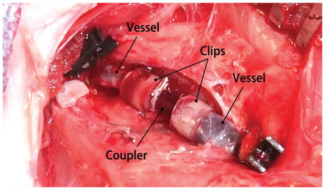
Digital photogragh of the completed anastomosis of a transected porcine femoral vein segments using the sutureless silk device.
Histology
Histological sections revealed cellular infiltration within the laminar structure of the male component, as well as at the interface between the male and female components [Figure 7]. Histological sections exhibited artifacts in the form of shrinking of the implant walls and separation of neointimal tissue from the implant. However, initial stages of degradation and absorption of the implant wall were also observed. Hematoxylin and Eosin (H & E) staining of the occlusion developed within the device demonstrated the organization and the presence of recanalization [Figure 7(A)]. Factor VIII immunohistochemistry demonstrated that the recanalization was lined with endothelial cells [Figure 7(B)]. Collagen deposition was revealed using Trichrome staining [Figure 7(C)]. Cells within the occlusion and recanalization were positive for smooth muscle actin suggesting the occlusion was a result of smooth muscle hyperplasia [Figure 7(D)].
FIGURE 7.

(a) H & E staining of the occlusion developed within the device (b) Factor VIII demonstrate the recanalization is lined with endothelial cells (c) Trichrome staining reveal collagen has been deposited within the occlusion (d) Cells within the occlusion and recanalization are positive for smooth muscle actin suggesting smooth muscle hyperplasia.
DISCUSSION
The robotic deposition system developed to deposit layers of silk:glycerol solution as a printable bio-ink for rapid prototyping of implants facilitated consistent outcomes and control over the fabrication process. Silk fibroin was used as the structural material, due to strength and potential for tissue regeneration.19,20 Silk fibroin can be classified as an enzymatically degradable polymer whereby proteolytic enzymes cleave regions of the protein into metabolizable peptides and amino acids.21–23 Regenerated silk fibroin-based materials can be tuned such that degradation in vivo is consistent with vascular regeneration. As examples, the mechanical strength of some silk materials has been programmed to be reduced by 55% to 85% over 6 to 10 weeks in vivo, with complete degradation within 2 to 6 months.24–26 Glycerol is a simple metabolizable non-toxic sugar alcohol ubiquitous in food and pharmaceutical industries. When blended, glycerol stabilizes an intermediate conformation of crystallized silk which produces a more flexible yet strong and insoluble material.14 This is the basis for the self-curing rapid prototyping strategy which does not require additional deleterious processing to aid curing. The silk material can also be sterilized using several methods without loss of mechanical integrity.27
The in vitro testing demonstrated vascular devices fabricated as silk film laminates using robotic deposition have adequate mechanical strength to perform intended functions. The multi-piece design of the RP vascular devices require the printed laminate constructs to support both tensile and radial compressive strengths in order to function. Assembled devices printed with 300 μm walls demonstrated compressive strength comparable to metal self-expanding stents and resisted burst pressures one order of magnitude greater than physiological requirements. These properties allowed the device to suturelessly coapt transected femoral vein segments in vivo, and maintain the anastomosis as a concentric compression fitting; demonstrating the resiliency of printed silk devices.
The three-piece design also facilitated faster anastomosis times compared to other reported strategies. Average reported time to complete double-sided anastomosis via manual suturing was reported in the range of 17 to 55 minutes.28–30 As an alternative to sutures, nitinol and titanium clips which are crimped in an interrupted pattern to anchor vessel ends have been developed.6,31 The average reported time to complete anastomosis for both ends of a vascular graft ranges from 14 to 18 minutes.6,31–33 Alternatives to anastomosis clips, such as stapling cartridges and ring pin staples use a minimal number of components in order to complete anastomosis with a single crimping motion but require an intricate loading process which extend the average procedure from 14 to 30 minutes.7,30,34
In contrast, the average length to perform a double sided anastomosis using the silk devices designed here was approximately 1 minute. The quick procedure was due to the implementation of novel anastomotic strategy. The slide and seat assembly design which allowed the components to concentrically self-align and complete the formation of the concentric seal was dependent on the flexibility and radial strength of the polymer body. Additionally, the assembly provided tactile confirmation of anastomosis in the form of a steep decrease followed by increased insertion resistance, as the coupler barb was positioned into the clip recesses and became fully seated. These qualities reduced technical dexterity requirements during device implantation. Porcine animal models allowed a more accurate design and analysis of implant geometries appropriate for humans, and thus allowed insight into surgical strategies and to the hurdles of human size implantation procedures. The femoral vessels, which span from the knee to groin, are large vessels subjected to significant mechanical strains in mobile animals. These strains are transferred to the anastomosis device and can be a source of failure. Initial implantation of the coupler into the femoral vein was impeded by vessel retraction after transection. The couplers were designed to function with minimal axial length. Anastomoses of the gap, which developed between vessel stumps, required a large amount of axial strain to be applied to the device. However, our design can be fabricated in various lengths to provide dual function as a vascular graft between vessel segments.
The influence of the device on vascular outcomes at the site of anastomosis was assessed relevant to endothelialization and smooth muscle hyperplasia. The degree of neointimal tissue was consistent with what was seen for metal and polymeric vascular implants, such as stents and grafts, implanted in the absence of long-term antiproliferative or antithrombotic drug therapies or, in some cases, with delivery of suboptimal therapeutics.35–39 The resorbable nature of silk has an impact on surface texture which may dictate implant shelf-life and storage strategies. Surface roughness has a large effect on platelet deposition but the roughness of the silk implant body was negligible at the time of initial fabrication, and remained minimal and within the range of current stents at the storage time point of 1 month.40,41
Anti-proliferatives, and standard drug therapies were excluded from our initial study to generate an understanding of the baseline occlusion in the absence of commonly administered treatments. Preliminary observations of neointimal tissue development in the absence of drug therapies will provide an understanding necessary to formulating a drug therapy optimized specifically to the device. Future drug therapies accompanying the device will likely include everolimus to target hyperplasia in order to compare the present data.
The erosion of the silk device designed here progresses from the luminal surface due to direct contact with fluid flow. Deposition of multiple layers of silk could be used to entrap various drugs within in each layer of the device which would elute as the couplers erode in vivo. This capability is enhanced because the silk bio-ink strategy is not dependent on high temperature, UV, or chemical crosslinking which would otherwise negatively impact incorporated biologicals such as antithrombotics or antiproliferatives. This approach presents a unique opportunity to locally deliver multiple drugs over several time scales to treat a variety of clinical conditions. The ambient processing conditions of silk facilitate the incorporation of sensitive drugs. This is a clear advantage to using resorbable polymer-based devices over metal-based implants.
CONCLUSIONS
The majority of vascular anastomotic failures are thought to be due to technical errors as manual suturing demands a high degree of technical skill and dexterity. The goal of this work was to rapid prototype a mechanically sufficient and quicker sutureless anastomosis mechanism using resorbable materials capable of drug-elution. The design and material were developed after surveying the advancements and limitations of competitive approaches. The silk material facilitated fabrication without the need for toxic solvents curing mechanisms and can be fabricated in a variety of diameters and lengths to support various anastomosis scenarios. The axial retention and burst strength were evaluated, as was the resistance generated by the implant geometry. Anastomoses formed using the device were secure and supported burst pressures and flow-rates one order of magnitude beyond physiological peaks. The anastomosis device remained intact when implanted in the femoral vein in vivo for the length of the 28 day study. The robust tensile and compressive performance of the biomaterial device provide evidence that robotic deposition of bio-ink solutions can be a viable option for rapid prototyping of biomedical implants. Future development will be focused on addressing neointimal tissue growth and tuning flexibility and permeability of the device body. Initial strategies will include incorporating antiproliferative and antithrombotic therapies, as standardized by the industry. The speed per anastomosis using the device was one of the fastest reported, requiring a fraction of the time compared to modern clinically available options. Much of the time saved is due to the minimalistic component system with an intuitive self-aligning concentric design, the single circumferentially lined seal, and the positive tactile confirmation of completion. The device has the potential to decrease complexity of procedures and to minimize ischemia and surgical times, while providing confidence in the anastomotic seal. The design may also support future strategies compatible with the use of less invasive catheter or robotic mediated procedures.
Acknowledgments
This work was supported by NIH awards P41 EB002520 and 3 P41 EB002520-09S1. The authors thank Scott Maccorkle and Denis Dupuis for their machining expertise.
Contributor Information
Rod R. Jose, Department of Biomedical Engineering, Tufts University, Science and Technology Center, 4 Colby Street, Medford, MA 02155, USA.
Waseem K. Raja, Department of Biomedical Engineering, Tufts University, Science and Technology Center, 4 Colby Street, Medford, MA 02155, USA.
Dr. Ahmed M. S. Ibrahim, Division of Plastic and Reconstructive Surgery, Beth Israel Deaconess Medical Center, Harvard Medical School, 110 Francis Street, Boston, MA 02215, USA
Dr. Pieter G. L. Koolen, Division of Plastic and Reconstructive Surgery, Beth Israel Deaconess Medical Center, Harvard Medical School, 110 Francis Street, Boston, MA 02215, USA
Dr. Kuylhee Kim, Division of Plastic and Reconstructive Surgery, Beth Israel Deaconess Medical Center, Harvard Medical School, 110 Francis Street, Boston, MA 02215, USA
Abdurrahman Abdurrob, Department of Biomedical Engineering, Tufts University, Science and Technology Center, 4 Colby Street, Medford, MA 02155, USA.
Jonathan A. Kluge, Department of Biomedical Engineering, Tufts University, Science and Technology Center, 4 Colby Street, Medford, MA 02155, USA
Professor Dr. Samuel J. Lin, Division of Plastic and Reconstructive Surgery, Beth Israel Deaconess Medical Center, Harvard Medical School, 110 Francis Street, Boston, MA 02215, USA
Professor David L. Kaplan, Email: david.kaplan@tufts.edu, Department of Biomedical Engineering, Tufts University, Science and Technology Center, 4 Colby Street, Medford, MA 02155, USA.
References
- 1.Beris AE, Lykissas MG, Korompilias AV, Mitsionis GI, Vekris MD, Kostas-Agnantis IP. Digit and hand replantation. Arch Orthop Trauma Surg. 2010;130:1141–7. doi: 10.1007/s00402-009-1021-7. [DOI] [PubMed] [Google Scholar]
- 2.Zubilewicz T, Wronski J, Bourriez A, Terlecki P, Guinault AM, Muscatelli-Groux B, Michalak J, Méllière D, Becquemin JP, Allaire E. Injury in vascular surgery--the intimal hyperplastic response. Med Sci Monit. 2001;7:316–24. [PubMed] [Google Scholar]
- 3.Disa JJ, Cordeiro PG, Hidalgo DA. Efficacy of conventional monitoring techniques in free tissue transfer: an 11-year experience in 750 consecutive cases. Plast Reconstr Surg. 1999;104:97–101. [PubMed] [Google Scholar]
- 4.Bui DT, Cordeiro PG, Hu Q-Y, Disa JJ, Pusic A, Mehrara BJ. Free flap reexploration: indications, treatment, and outcomes in 1193 free flaps. Plast Reconstr Surg. 2007;119:2092–100. doi: 10.1097/01.prs.0000260598.24376.e1. [DOI] [PubMed] [Google Scholar]
- 5.Pratt G, Rozen W, Westwood A, Hancock A, Chubb D, Ashton MW, Whitaker IS. Technology-assisted and sutureless microvascular anastomoses: Evidence for current techniques. Microsurgery. 2012;32:68–76. doi: 10.1002/micr.20930. [DOI] [PubMed] [Google Scholar]
- 6.Bigdeli AK, Kaczmarek I, Eifert S, Beiras-Fernandez A, Kober S, Nikolaou K, Oberhoffer M, Vicol C. Interrupted nitinol U-Clips versus standard running suture for the central arterial T-graft anastomosis: a prospective randomized study. Eur J Cardiothorac Surg. 2011;40:e93–7. doi: 10.1016/j.ejcts.2011.02.078. [DOI] [PubMed] [Google Scholar]
- 7.Ye G, Mo H-G, Wang Z-H, Yi S-H, Wang X-W, Zhang Y-F. Arterial anastomosis without sutures using ring pin stapler for clinical renal transplantation: comparison with suture anastomosis. J Urol. 2006;175:636–40. doi: 10.1016/S0022-5347(05)00143-6. [DOI] [PubMed] [Google Scholar]
- 8.Wall J, Diana M, Leroy J, Deruijter V, Gonzales KD, Lindner V, Harrison M, Marescaux J. MAGNAMOSIS IV: magnetic compression anastomosis for minimally invasive colorectal surgery. Endoscopy. 2013;45:643–8. doi: 10.1055/s-0033-1344119. [DOI] [PubMed] [Google Scholar]
- 9.Gonzalez I, Kenny D, Slyder S, Hijazi ZM. Medium and Long-Term Outcomes After Bilateral Pulmonary Artery Stenting in Children and Adults With Congenital Heart Disease. Pediatr Cardiol. 2013;34:179–84. doi: 10.1007/s00246-012-0439-9. [DOI] [PubMed] [Google Scholar]
- 10.Lekakou C, Lamprou D, Vidyarthi U, Karopoulou E, Zhdan P. Structural hierarchy of biomimetic materials for tissue engineered vascular and orthopedic grafts. J Biomed Mater Res B Appl Biomater. 2008;85:461–8. doi: 10.1002/jbm.b.30966. [DOI] [PubMed] [Google Scholar]
- 11.Sgarioto M, Adhikari R, Gunatillake PA, Moore T, Malherbe F, Nagel M-D, Patterson J. Properties and in vitro evaluation of high modulus biodegradable polyurethanes for applications in cardiovascular stents. J Biomed Mater Res B Appl Biomater. 2014 doi: 10.1002/jbm.b.33137. [DOI] [PubMed] [Google Scholar]
- 12.Ueda K, Mukai T, Ichinose S, Koyama Y, Takakuda K. Bioabsorbable device for small-caliber vessel anastomosis. Microsurgery. 2010;30:494–501. doi: 10.1002/micr.20764. [DOI] [PubMed] [Google Scholar]
- 13.Lovett ML, Cannizzaro C, Daheron L, Messmer B. Silk fibroin microtubes for blood vessel engineering. Biomaterials. 2007;28:5271–9. doi: 10.1016/j.biomaterials.2007.08.008. [DOI] [PMC free article] [PubMed] [Google Scholar]
- 14.Lu S, Wang X, Lu Q, Zhang X, Kluge JA, Uppal N, Omenetto F, Kaplan DL. Insoluble and flexible silk films containing glycerol. Biomacromolecules. 2010;11:143–50. doi: 10.1021/bm900993n. [DOI] [PubMed] [Google Scholar]
- 15.Lawrence BD, Wharram S, Kluge Ja, Leisk GG, Omenetto FG, Rosenblatt MI, Kaplan DL. Effect of hydration on silk film material properties. Macromol Biosci. 2010;10:393–403. doi: 10.1002/mabi.200900294. [DOI] [PMC free article] [PubMed] [Google Scholar]
- 16.Ormiston JA, Serruys PWS. Bioabsorbable coronary stents. Circ Cardiovasc Interv. 2009;2:255–60. doi: 10.1161/CIRCINTERVENTIONS.109.859173. [DOI] [PubMed] [Google Scholar]
- 17.Stick C, Hiedl U, Witzleb E. Venous pressure in the saphenous vein near the ankle during changes in posture and exercise at different ambient temperatures. Eur J Appl Physiol Occup Physiol. 1993;66:434–8. doi: 10.1007/BF00599617. [DOI] [PubMed] [Google Scholar]
- 18.Von Schroeder HP, Coutts RD, Billings E, Mai MT, Aratow M. The changes in intramuscular pressure and femoral vein flow with continuous passive motion, pneumatic compressive stockings, and leg manipulations. Clin Orthop Relat Res. 1991:218–26. [PubMed] [Google Scholar]
- 19.Kasoju N, Bora U. Silk fibroin in tissue engineering. Adv Healthc Mater. 2012;1:393–412. doi: 10.1002/adhm.201200097. [DOI] [PubMed] [Google Scholar]
- 20.Kaewprasit K, Promboon A, Kanokpanont S, Damrongsakkul S. Physico-chemical properties and in vitro response of silk fibroin from various domestic races. J Biomed Mater Res B Appl Biomater. 2014 doi: 10.1002/jbm.b.33142. [DOI] [PubMed] [Google Scholar]
- 21.Li M, Ogiso M, Minoura N. Enzymatic degradation behavior of porous silk fibroin sheets. Biomaterials. 2003;24:357–65. doi: 10.1016/s0142-9612(02)00326-5. [DOI] [PubMed] [Google Scholar]
- 22.Altman GH, Diaz F, Jakuba C, Calabro T, Horan RL, Chen J, Lu H, Richmond J, Kaplan DL. Silk-based biomaterials. Biomaterials. 2003;24:401–16. doi: 10.1016/s0142-9612(02)00353-8. [DOI] [PubMed] [Google Scholar]
- 23.Arai T, Freddi G, Innocenti R, Tsukada M. Biodegradation of bombyx mori silk fibroin fibers and films. J Appl Polym Sci. 2004;91:2383–90. [Google Scholar]
- 24.Wang Y, Rudym DD, Walsh A, Abrahamsen L, Kim HJ, Kim HS, Kirker-Head C, Kaplan DL. In vivo degradation of three-dimensional silk fibroin scaffolds. Biomaterials. 2008;29:3415–28. doi: 10.1016/j.biomaterials.2008.05.002. [DOI] [PMC free article] [PubMed] [Google Scholar]
- 25.Meinel L, Hofmann S, Karageorgiou V, Kirker-Head C, McCool J, Gronowicz G, Zichner L, Langer R, Vunjak-Novakovic G, Kaplan DL. The inflammatory responses to silk films in vitro and in vivo. Biomaterials. 2005;26:147–55. doi: 10.1016/j.biomaterials.2004.02.047. [DOI] [PubMed] [Google Scholar]
- 26.Greenwald D, Shumway S, Albear P, Gottlieb L. Mechanical comparison of 10 suture materials before and after in vivo incubation. J Surg Res. 1994;56:372–7. doi: 10.1006/jsre.1994.1058. [DOI] [PubMed] [Google Scholar]
- 27.De Moraes MA, Weska RF, Beppu MM. Effects of sterilization methods on the physical, chemical, and biological properties of silk fibroin membranes. J Biomed Mater Res B Appl Biomater. 2014;102:869–76. doi: 10.1002/jbm.b.33069. [DOI] [PubMed] [Google Scholar]
- 28.Abou Taam S, Garbé J-F, Boufi M, Bossavy J-P, Ricco J-B. Experimental study of a novel mechanical connector for sutureless open arterial anastomosis. J Vasc Surg Elsevier Inc. 2012;55:210–5. doi: 10.1016/j.jvs.2011.07.082. [DOI] [PubMed] [Google Scholar]
- 29.Alghoul MS, Gordon CR, Yetman R, Buncke GM, Siemionow M, Afifi AM, Moon WK. From simple interrupted to complex spiral: a systematic review of various suture techniques for microvascular anastomoses. Microsurgery. 2011;31:72–80. doi: 10.1002/micr.20813. [DOI] [PubMed] [Google Scholar]
- 30.Rozen WM, Whitaker IS, Acosta R. Venous coupler for free-flap anastomosis: outcomes of 1,000 cases. Anticancer Res. 2010;30:1293–4. [PubMed] [Google Scholar]
- 31.Zeebregts CJ. Randomized clinical trial of continuous sutures or non-penetrating clips for radiocephalic arteriovenous fistula (Br J Surg 2004; 91: 1438–1442) Br J Surg. 2005;92:654–5. doi: 10.1002/bjs.5063. [DOI] [PubMed] [Google Scholar]
- 32.Baynosa RC, Stutman R, Mahabir RC, Zamboni WA, Khiabani KT. Use of a novel penetrating, sutureless anastomotic device in arterial microvascular anastomoses. J Reconstr Microsurg. 2008;1:39–42. doi: 10.1055/s-2008-1064926. [DOI] [PubMed] [Google Scholar]
- 33.Taylor J, Katz R, Singh N. Use of the U-clip for microvascular anastomosis. Microsurgery. 2006;26:550–1. doi: 10.1002/micr.20286. [DOI] [PubMed] [Google Scholar]
- 34.Liu L, Liu J, Zhu M, Hu S. Experimental study of one-shot vascular anastomostic device for proximal vein graft anastomoses. Ann Thorac Surg. 2006;82:303–6. doi: 10.1016/j.athoracsur.2006.01.099. [DOI] [PubMed] [Google Scholar]
- 35.Hamilos M, Sarma J, Ostojic M, Cuisset T, Sarno G, Melikian N, Ntalianis A, Muller O, Barbato E, Beleslin B, Sagic D, De Bruyne B, Bartunek J, Wijns W. Interference of drug-eluting stents with endothelium-dependent coronary vasomotion: evidence for device-specific responses. Circ Cardiovasc Interv. 2008;1:193–200. doi: 10.1161/CIRCINTERVENTIONS.108.797928. [DOI] [PubMed] [Google Scholar]
- 36.Palmerini T, Biondi-Zoccai G, Della Riva D, Stettler C, Sangiorgi D, D’Ascenzo F, Kimura T, Briguori C, Sabatè M, Kim H-S, De Waha A, Kedhi E, Smits PC, Kaiser C, Sardella G, Marullo A, Kirtane AJ, Leon MB, Stone GW. Stent thrombosis with drug-eluting and bare-metal stents: evidence from a comprehensive network meta-analysis. Lancet Elsevier Ltd. 2012;379:1393–402. doi: 10.1016/S0140-6736(12)60324-9. [DOI] [PubMed] [Google Scholar]
- 37.Gonzalo N, Macaya C. Absorbable stent: focus on clinical applications and benefits. Vasc Health Risk Manag. 2012;8:125–32. doi: 10.2147/VHRM.S22551. [DOI] [PMC free article] [PubMed] [Google Scholar]
- 38.Van der Giessen WJ, Lincoff a M, Schwartz RS, van Beusekom HM, Serruys PW, Holmes DR, Ellis SG, Topol EJ. Marked inflammatory sequelae to implantation of biodegradable and nonbiodegradable polymers in porcine coronary arteries. Circulation. 1996;94:1690–7. doi: 10.1161/01.cir.94.7.1690. [DOI] [PubMed] [Google Scholar]
- 39.Vasić N, Davidović L, Marković D, Sladojević M. Long-term graft occlusion in aortobifemoral position. Vojnosanit Pregl. 2013;70:740–6. doi: 10.2298/vsp110404002v. [DOI] [PubMed] [Google Scholar]
- 40.Linneweber J, Dohmen PM, Kertzscher U, Kerzscher U, Affeld K, Nosé Y, Konertz W. The effect of surface roughness on activation of the coagulation system and platelet adhesion in rotary blood pumps. Artif Organs. 2007;31:345–51. doi: 10.1111/j.1525-1594.2007.00391.x. [DOI] [PubMed] [Google Scholar]
- 41.Dibra A, Kastrati A, Mehilli J, Pache J, von Oepen R, Dirschinger J, Schömig A. Influence of stent surface topography on the outcomes of patients undergoing coronary stenting: a randomized double-blind controlled trial. Catheter Cardiovasc Interv Off J Soc Card Angiogr Interv. 2005;65:374–80. doi: 10.1002/ccd.20400. [DOI] [PubMed] [Google Scholar]