Abstract
Stereotaxy is a neurosurgical technique that can take several hours to reach a specific target, typically utilizing a mechanical frame and guided by preoperative imaging. An error in any one of the numerous steps or deviations of the target anatomy from the preoperative plan such as brain shift (up to 20 mm), may affect the targeting accuracy and thus the treatment effectiveness. Moreover, because the procedure is typically performed through a small burr hole opening in the skull that prevents tissue visualization, the intervention is basically “blind” for the operator with limited means of intraoperative confirmation that may result in reduced accuracy and safety. The presented system is intended to address the clinical needs for enhanced efficiency, accuracy, and safety of image-guided stereotactic neurosurgery for Deep Brain Stimulation (DBS) lead placement. The work describes a magnetic resonance imaging (MRI)-guided, robotically actuated stereotactic neural intervention system for deep brain stimulation procedure, which offers the potential of reducing procedure duration while improving targeting accuracy and enhancing safety. This is achieved through simultaneous robotic manipulation of the instrument and interactively updated in situ MRI guidance that enables visualization of the anatomy and interventional instrument. During simultaneous actuation and imaging, the system has demonstrated less than 15% signal-to-noise ratio (SNR) variation and less than 0.20% geometric distortion artifact without affecting the imaging usability to visualize and guide the procedure. Optical tracking and MRI phantom experiments streamline the clinical workflow of the prototype system, corroborating targeting accuracy with 3-axis root mean square error 1.38 ± 0.45 mm in tip position and 2.03 ± 0.58° in insertion angle.
Index Terms: MRI-compatible robotics, robot-assisted surgery, image-guided therapy, stereotactic neurosurgery, deep brain stimulation
I. Introduction
Stereotactic neurosurgery enables surgeons to target and treat diseases affecting deep structures of the brain, such as through stereotactic electrode placement for deep brain stimulation (DBS). However, the procedure is still very challenging and often results in non-optimal outcomes. This procedure is very time-consuming, and may takes 5 – 6 hours with hundreds of steps. It follows a complicated workflow including preoperative MRI (typically days before the surgery), preoperative Computed Tomography (CT), and intraoperative MRI-guided intervention (where available). The procedure suffers from tool placement inaccuracy that is related to errors in one or more steps in the procedure, or is due to brain shift that occurs intraoperatively. According to [1], the surface of the brain is deformed by up to 20 mm after the skull is opened during neurosurgery, and not necessarily in the direction of gravity. The lack of interactively updated intraoperative image guidance and confirmation of instrument location renders this procedure nearly “blind” without any image-based feedback.
DBS, the clinical focus of this paper, is a surgical implant procedure that utilizes a device to electrically stimulate specific structures. DBS is commonly used to treat the symptoms of motion disorders such as Parkinson’s disease, and has shown effective for various other disorders including obsessive-compulsive disorder and severe depression. Unilateral lead is implanted to the subthalamic nucleus (STN) or globus pallidus interna (GPi) for Parkinson’s disease and dystonia. While bilateral leads are implanted to the ventral intermediate nucleus of the thalamus (VIM). Recently, improvement in intervention accuracy has been achieved through direct MR guidance in conjunction with manual frames such as the NexFrame (Medtronic, Inc, USA) [2] and Clearpoint (MRI Interventions, Inc., USA) [3] for DBS. However, four challenges are still not addressed. First, manual adjustment of the position and orientation of the frame is non-intuitive and time-consuming. Moreover, the clinician needs to mentally solve the inverse kinematics to align the needle. Second, manually-operated frames have limited positioning accuracy, inferior to a motorized closed-loop control system. Third, the operational ergonomics, especially the hand-eye coordination, is awkward during the procedure (the operator has to reach about 1 meter inside the scanner) while observing the MRI display (outside of the scanner). Fourth, most importantly, real-time confirmation of the instrument position is still lacking.
To address these issues, robotic assistants, especially that are compatible inside MRI environment have been studied. Non-MRI compatible NeuroMate robot (Renishaw Inc., United Kingdom) had a reported accuracy of 1.7 mm for DBS electrode placement in 51 patients, although many cases required several insertion attempts and errors due to brain shift led to sufficient accuracy in only 37 of 50 targets [4]. Masamune et al. [5] designed an MRI-guided robot for neurosurgery with ultrasonic motors (USR30-N4, Shinsei Corporation, Japan) inside low field strength scanners (0.5 Tesla) in 1995. Yet, stereotaxy requires high-field MRI (1.5–3 Tesla) to achieve adequate precision. Sutherland et al. [6] developed NeuroArm robot, a manipulator consisting of dual dexterous arms driven by piezoelectric motors (HR2-1N-3, Nanomotion Ltd, Israel) for operation under MR guidance. Since this general purpose neurosurgery robot aims to perform both stereotaxy and microsurgery with a number of tools, the cost could be formidably high. Ho et al. [7] developed a shape-memory-alloy driven finger-like neurosurgery robot. This technology shows promise, however, it is still in the early development and requires high temperature intracranially with very limited bandwidth. Comber et al. [8] presented a pneumatically actuated concentric tube robot for MRI-guided neurosurgery. However, the inherent nonlinearity and positioning limitation of pneumatic actuation, as demonstrated in [9], present significant design challenge. Augmented reality has also been shown effectiveness to improve the MRI-guided interventions by Liao et al. [10] and Hirai et al. [11].
There is a critical unmet need for an alternative approach that is more efficient, more accurate, and safer than traditional stereotactic neurosurgery or manual MR-guided approaches. A robotic solution can increase the accuracy over the manual approach, however its inability to visualize the anatomy and instrument during intervention due to incompatibility with the MR scanner limits the safety and accuracy. Simultaneous precision intervention and interactively updated imaging is critical to guide the procedure either for brain shift compensation or target confirmation. However, there have been great challenges in developing actuation approaches appropriate for use in the MRI environment. Piezoelectric and pneumatic actuators are the mainstay approaches for robotic manipulation inside MRI. Piezoelectric actuators can offer nanometer level accuracy without overshooting, but typically cause 26 – 80% SNR loss with commercial off-the-shelf motor driver during motor operation even with motor shielding [12]. Pneumatic actuators, either customized pneumatic cylinders from our group [13] or novel pneumatic steppers [14] tends to be difficult to control, especially in a dynamic manner. The one developed by Yang et al. [9] demonstrated 2.5 – 5 mm steady state error due to oscillations for a single axis motion. Reviews of MRI-guided robotics about piezoelectric and pneumatic actuation can be found in [15], [16], and [17].
To address these unmet clinical needs, this paper proposes a piezoelectrically-actuated cannula placement robotic assistant that allows simultaneous imaging and intervention without negatively impacting MR image quality for neurosurgery, specifically for DBS lead placement. In previous publications, the mechanism concept of this robot was explored [18], [19], whereas the detailed mechanical design of the robot, electrical design of the motor control system, control software or accuracy evaluation was not developed. This paper presents the complete electromechanical design, system integration, MRI compatibility and accuracy evaluation of a fully functional prototype system. The mechanism is the first robotic embodiment that is kinematically equivalent to traditionally used manual stereotactic frames such as the Leksell frame (Elekta AB, Sweden). The primary contributions of the paper include: 1) a novel design of an MRI-guided robot that is kinematically equivalent to a Leksell frame; 2) a piezoelectric motor control system that allows simultaneous robot motion and imaging without affecting the imaging usability to visualize and guide the procedure; 3) robot-assisted workflow analysis demonstrating the potential to reduce procedure time, and 4) imaging quality and accuracy evaluation of the robotic system.
II. Clinical Workflow of MRI-Guided Robotic Neurosurgery
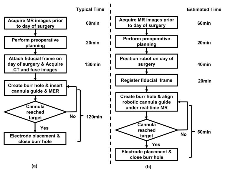
The current typical workflow for DBS stereotactic neurosurgery involves numerous steps. The following list describes the major steps as illustrated in Fig. 1(a):
Fig. 1.
Workflow comparison of manual frame-based approach and MRI-guided robotic approach for unilateral DBS lead placement. (a) Workflow of a typical lead placement with measured average time per step. (b) Workflow of an MRI-guided robotic lead placement with estimated time per step.
Acquire MR images prior to day of surgery;
Perform preoperative surgical planning;
Surgically attach fiducial frame;
Interrupt procedure to acquire CT images;
Fuse preoperative MRI-based plan to preoperative CT;
Use stereotactic frame to align the cannula guide and place the cannula.
Optionally confirm placement with non-visual approach such as microelectrode recording (MER, a method that uses electrical signals in the brain to localize the surgical site) and/or visual approach such as fluoroscopy which can localize the instrument but not the target anatomy.
During the workflow, there are hundreds of points where errors could be introduced, these errors are categorized as three main subtypes : 1) those associated with planning, 2) with the frame, and 3) with execution of the procedure. Our approach, especially the new workflow, as shown in Fig. 1(b), addresses all these three errors. First, error due to discrepancies between the preoperative plan and the actual anatomy (because of brain shift) may be attenuated through the use of intraoperative MR imaging. Second, closed-loop controlled robotic needle alignment eliminates the mental registration between image and actual anatomy, while provides precise motion control in contrast to the inaccurate manual frame alignment. Third, errors that arise with execution would be compensated with intraoperative interactively updated MR image feedback. To sum up, by attenuating all three error sources, these advantages enabled by the robotic system could potentially improve interventional accuracy and outcomes.
The procedure duration is potentially reduced significantly from two aspects: 1) avoiding a CT imaging session and corresponding image fusion and registration, and 2) using direct image guidance instead of requiring additional steps using MER. As shown in Fig. 1(b) : 1) The proposed approach completely removes the additional perioperative CT imaging session potentially saving about one hour of procedure time and the complex logistics of breaking up the surgical procedure for CT imaging. 2) During the electrode placement, the current guidance and confirmation method relies on microelectrode recording, a one-dimensional signal to indirectly localize the target. MER localization takes about 40 minutes in an optimal scenario, and could take one hour more if not. In contrast to the indirect, iterative approach with MER, the proposed system utilizes MR imaging to directly visualize placement. Eliminating the need for MER may reduce about one hour of procedure time per electrode, and in the typical DBS procedure with bilateral insertion this would result in a benefit of two hours. Therefore, for a bilateral insertion the benefit in reduced intraoperative time could potentially be as great as three hours, on top of the benefits of improved planning and accurate execution of that plan.
III. Electromechanical System Design
This section presents the electromechanical design of the robotic system. The configuration of this system in the MR scanner suite is illustrated in Fig. 2. Planning is performed on pre-procedure MR images or preoperative images registered to the intra-operative images. The needle trajectories required to reach these desired targets are evaluated, subject to anatomical constraints, as well as constraints of the needle placement mechanism. The desired targets selected in the navigation software 3D Slicer [20] are sent to the robot control software through OpenIGTLink communication protocol [21], wherein resolved to the motion commands of individual joints via kinematics. The commands are then sent to the custom MRI robot controller, which can provide high precision closed-loop control of piezoelectric motors, to drive the motors and move the robot to the desired target positions. The actual needle position is fed back to the navigation software in image space for verification and visualization.
Fig. 2.
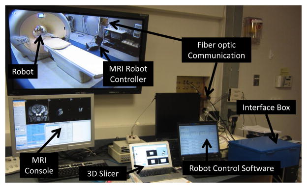
Configuration of the MRI-guided robotic neurosurgery system. The stereotactic manipulator is placed within the scanner bore and the MRI robot controller resides inside the scanner room. The robot controller communicates with the control computer within the Interface Box through a fiber optic link. The robot control software running on the control computer communicates with 3D Slicer navigation software through OpenIGTLink.
To increase clinician comfort operating the device, as well as limiting the system’s complexity, cost and training required to operate and maintain the equipment, the robot mechanism is designed to be kinematically equivalent to the clinically used manual stereotactic device Leksell stereotactic surgical frame. Electrically, some research groups have utilized methods to reduce MRI artifact by avoiding operating electromechanical actuation during live imaging, such as interleaving robot motion and MR imaging as demonstrated by Krieger et al. [12], or utilizing less precise but reliable pneumatic actuation methods demonstrated by Fischer et al. [22]. In contrast to these approaches, we have developed a custom piezoelectric motor control system that induces no visually observable image artifact.
A. Actuators and Sensors for Applications in MRI Environment
As has been discussed earlier, the harsh electromagnetic environment of the scanner bore poses a great challenge to the construction of MRI compatible robotic systems. American Society for Testing and Materials (ASTM) and U.S. Food and Drug Administration (FDA) defined that “MR Safe” as an item that poses no known hazard in all MRI environments. “MR Safe” items are non-conducting, non-metallic, and non-magnetic. This definition is about safety, while neither image artifact nor proper functioning of a device is covered. From the perspective of interventional mechatronics, the term “MRI-compatibility” is defined [23] such that all components inside scanner room have been demonstrated
not to pose any known hazards in its intended configuration (corresponding to the ASTM definition of MR Conditional),
not to have its intended functions deteriorated by the MRI system,
not to significantly affect the quality of the diagnostic information,
in the context of a defined application, imaging sequence and configuration within a specified MRI environment.
The interference of a robotic system with the MR scanner is attributed to its mechanical (primarily material) and electrical properties. From a materials perspective, ferromagnetic materials must be avoided entirely, though non-ferrous metals such as aluminum, brass, nitinol and titanium, or composite materials can be used with caution. In this robot, all electrical and metallic components are isolated from the patient’s body. Non-conductive materials are utilized to build the majority of the components of the mechanism, i.e. base structure are made of 3D printed plastic materials and linkages are made out of high strength, bio-compatible plastics including Ultem and PEEK.
From an electrical perspective, conductors passing through the patch panel or wave guide could act as antennas, introducing stray RF noise into scanner room and thus resulting in image quality degradation. For this reason, the robot controller is designed to be placed inside scanner room and communicate with a computer in the console room through fiber optic medium. Even in this configuration, however, electrical interference from the motors’ drive system can induce significant image quality degradation including SNR loss. There are two primary types of piezoelectric motors, harmonic and non-harmonic. Harmonic motors, such as Nanomotion motors (Nanomotion Ltd., Israel) and Shinsei motors (Shinsei Corporation, Japan), are generally driven with fixed frequency sinusoidal signal. Non-harmonic motors, such as PiezoLegs motors (PiezoMotor AB, Sweden), require a complex shaped waveform on four channels generated with high precision at fixed amplitude. Both have been demonstrated to cause interference within the scanner bore with commercially available drive systems. The SNR reduction is up to 80% [12] and 26% [24] for harmonic and non-harmonic motors respectively.
In this presented system, non-harmonic PiezoLegs motors have been selected. PiezoLegs motor has the required torque (50 mNm) but with small footprint (Ø23 × 34 mm). NanoMotion (HR2-1-N-10, Nanomotion Ltd., Israel) only offers linear motor with large footprint (40.5 mm × 25.7 mm × 12.7 mm) that has to be used in opposing pairs [12] for either linear or rotary motion. Shinsei motors (USR60-E3N, Shinsei Corporation, Japan) has bulky footprint (Ø67 × 45 mm) with torque 0.1 Nm.
Optical encoders (US Digital, Vancouver, WA) EM1-0-500-I linear (0.0127 mm/count) and EM1-1-1250-I rotary (0.072°/count) encoder modules are used. The encoders are placed on the joint actuators and reside in the scanner bore. Differential signal drivers sit on the encoder module, and the signals are transmitted via shielded twisted pairs cables to the controller. The encoders have been incorporated into the robotic device and perform without any evidence of stray or missed counts.
B. Mechanism Design
The robotic manipulator is designed to be kinematically equivalent to the commonly used Leksell stereotactic frame, and configured to place an electrode within a confined standard 3 Tesla Philips Achieva scanner bore with 60 cm diameter. The manual frame’s x, y and z axis set the target position, and θ4 and θ5 align the orientation of the electrode as shown in Fig. 3 (left). A preliminary design for the robotic manipulator based upon these requirements is described in our early work [18] where neither the actuator, motion transmission nor the encoder design was covered. The current work presents the first fully-developed functional prototype of this robot that has 5-axis motorized and encoded motion.
Fig. 3.
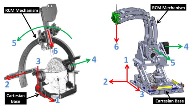
Equivalence of the degrees of freedom of a traditional manual stereotactic frame (left) and the proposed robotic system (right). Translation DOF in red, rotational DOF in green.
To mimic the functionality and kinematic structure of the manual stereotactic frame, a combination of a 3-DOF prismatic Cartesian motion base module and a 2-DOF remote center of motion (RCM) mechanism module are employed, as shown in Fig. 3 (right). The robot provides three prismatic motions for Cartesian positioning (DOF #1 – DOF #3), two rotary motions corresponding to the arc angles (DOF #4 and DOF #5), and a manual cannula guide (DOF #6). To maintain good stiffness of the robot in spite of the plastic material structure, three approaches have been implemented. 1) Parallel mechanism is used for the RCM linkage and Scott-Russell vertical motion linkages to take advantage of the enhanced stiffness due to the closed-chain structure; 2) High strength plastic Ultem (stiffness 1,300,000 pounds per square inch (PSI)) is machined to construct the RCM linkage. The Cartesian motion module base is primarily made of 3D printed ABS plastic (stiffness 304,000 PSI); 3) Non-ferrous aluminum linear rails constitutes mechanical backbone to maintain good structural rigidity.
1) Orientation Motion Module
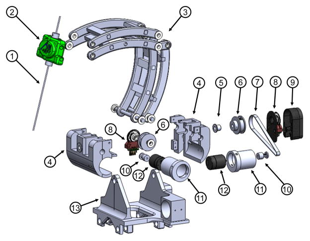
As portrayed in Fig. 4, the manipulator allows 0° – 90° rotation motion in the sagittal plane. The neutral posture is defined when the cannula/electrode (1) inside the headstock (2) is in vertical position. In the transverse plane, the required range of motion is ±45° about the vertical axis as specified in Table I. A mechanically constrained RCM mechanism, in the form of a parallelogram linkage (3) was designed. In order to reduce backlash, rotary actuation of RCM DOF are achieved via Kevlar reinforced timing belt transmissions (7), which are loaded via eccentric locking collars (11), eliminating the need for additional tension pulleys. The primary construction materials for this mechanism is polyetherimide (Ultem), due to its high strength, machinability, and suitability for chemical sterilization. This module mimics the arc angles of the tractional manual frame.
Fig. 4.
Exploded view of the RCM orientation module, showing (1) instrument/electrode, (2) headstock with cannula guide, (3) parallel linkage mechanism, (4) manipulator base frame, (5) flange bearings, (6) pulleys, (7) timing belts, (8) rotary encoders, (9) encoder housings, (10) pulleys, (11) eccentric locking collars, (12) rotary piezoelectric motors, (13) manipulator base.
TABLE I.
Joint Space Kinematic Specifications of The Robot
| Axis | Motion | Robot |
|---|---|---|
|
| ||
| 1 | x | ± 35mm |
| 2 | y | ± 35mm |
| 3 | z | ± 35mm |
| 4 | Sagittal plane angle | 0–90° |
| 5 | Transverse plane angle | ±45° |
| 6 | Needle insertion | 0–75mm |
2) Cartesian Motion Module
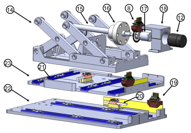
As shown in Fig. 5, linear travel through DOF #2 and #3 is achieved via direct drive where a linear piezoelectric motor (PiezoLegs LL1011C, PiezoMotor AB, Sweden), providing 6 N holding force and 1.5 cm/s speed, controls each decoupled 1-DOF motion. DOF #1 is actuated via scissor lift mechanism (known as Scott-Russell mechanism) driven by a rotary actuator (PiezoLegs, LR80, PiezoMotor AB, Sweden) and an aluminum anodized lead screw (2 mm pitch). This mechanism is compact and attenuates structural flexibility due to plastic linkages and bearings.
Fig. 5.
Exploded view of the Cartesian motion module, showing (14) Scott-Russell scissor mechanism, (15) lead-screw, (16) nut, (17) motor coupler, (18) motor housing, (19) linear encoder, (20) linear piezoelectric motor, (21) linear guide, (22) horizontal motion stage, (23) lateral motion stage.
3) Workspace Analysis
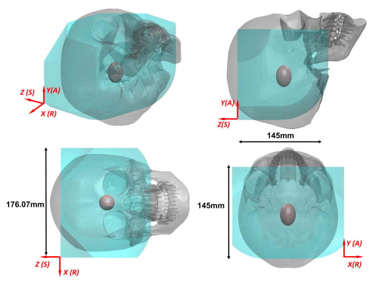
The range of motion of the robot was designed to cover the clinically required set of targets and approach trajectories (STN, GPi and VIM of the brain). As illustrated in Table I, the range of motion for placement of the robot’s center of rotation is ±35 mm, ±35 mm and ±35 mm in x, y and z axes respectively. With respect to this neutral posture, the robot has 0° – 90° rotation motion in the sagittal plane and ±45° in the transverse plane. For an electrode with 75 mm insertion depth, the reachable workspace of the robot for target locations is illustrated in Fig. 6 with respect to a representative skull model based on the head and face anthropometry of adult U.S. civilians [25]. The 95% percentile male head breath, length, and stomion to top of head measurements are 16.1, 20.9 and 19.9 cm respectively. This first prototype of the robot is able to cover the majority of brain tissue inside the skull. Since basal ganglia area is the typical DBS treatment target, which is approximated as a ellipsoid in Fig. 6. Although the workspace is slightly smaller than the skull, all typical targets and trajectories for the intended application of DBS procedures are reachable. The current robot workspace is also smaller than the Leksell frame since the later is a generic neurosurgery mechanism, while this robot is primarily tailored for DBS which has a much smaller workspace requirement.
Fig. 6.
Reachable workspace of the stereotactic neurosurgery robot overlaid on a representative human skull. The red ellipsoid represents the typical DBS treatment target, i.e. the basal ganglia area.
C. Piezoelectric Actuator Motion Control System
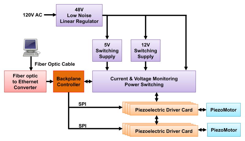
A key reason that commercially available piezoelectric motor drivers affect image quality is due to the high frequency switching signal. While a low-pass filter may provide benefit, it has not been effective in eliminating the interference and often significantly degrades motor performance. To address this issue, our custom motor controller utilize linear regulators and direct digital synthesizers (DDS) to produce the driving signal in combination with analog p filters. The control system comprises of four primary units as illustrated in Fig. 7: 1) the power electronics unit, 2) the piezoelectric driver unit which directly interfacing with the piezoelectric motors, 3) backplane controller unit, an embedded computer which translates high level motion information into device level commands, and 4) an interface box containing the fiber optic Ethernet communication hardware. The power electronics unit, piezoelectric drive unit and backplane controller unit are enclosed in an an electromagnetic interference (EMI) shielded enclosure. A user workstation, connected to the interface box in the console room, which operates the navigation software 3D Slicer is the direct interface for the physician.
Fig. 7.
Block diagram of the MRI robot control system. The power electronics and piezoelectric actuator drivers are contained in a shielded enclosure and connected to an interface unit in the console room through a fiber optic Ethernet connection.
The robot controller contains piezoelectric motor driver modules plugged into a backplane. The corresponding power electronics consists of cascaded regulators. The primary regulator (F48-6-A+, SL Power Electronics, USA) converting from the isolated, grounded 120 V AC supply in the MR scanner room to 48 V DC is a linear regulator chosen for its low noise. Two switching regulators modified to operate at ultra low frequencies with reduced noise generate the 5 V DC and 12 V DC (QS-4805CBAN, OSKJ, USA) power rails that drive the logic and analog preamplifiers of the control system, respectively. The 48 V DC from the linear regulator directly feeds the linear power amplifiers for the motor drive signals (through a safety circuit).
An innovation of the custom-developed motor driver is to use linear power amplifiers for each of the four drive channels of the piezoelectric motors and a field-programmable gate array (FPGA, Cyclone EP2C8Q208C8, Altera Corp., USA)-based direct digital synthesizer (DDS) as a waveform generator to fundamentally avoid these high frequency signals. As shown in Fig. 8, each motor control card module of the piezoelectric driver unit, consists of four DDS waveform generators. These generators output to two dual-channel high speed (125 million samples per second) digital-to-analog converters (DAC2904, Texas Instruments, USA) and then connect to four 48 V linear power amplifiers (OPA549, Texas Instruments, USA). The motor control card also has two Low-Voltage Differential Signaling (LVDS) receivers that connect to two quadrature encoders (one of which may be replaced with differential home and limit sensors). The motor control card has a micro-controller (PIC32MX460F512L, Microchip Tech., USA) that loads a predefined waveform image from a Secure Digital (SD) card into the FPGA’s DDS and then operates a feedback loop using the encoder output. The motor control cards are interconnected via Serial Peripheral Interface (SPI) bus to one backplane controller which communicates over fiber optic 100-FX Ethernet to the interface box in the room where a control PC running the user interface is connected.
Fig. 8.

Block diagram showing the key components of a piezoelectric motor driver card-based module.
IV. Experimental Evaluation and Results
Two primary sets for experiments were run to assess imaging compatibility with the MRI environment and positioning accuracy of the system. The effect of the robot on image quality was assessed through quantitative SNR analysis, quantitative geometric distortion analysis and qualitative human brain imaging. Targeting accuracy of this system was assessed in free space tested using an optical tracking system (OTS), and image-guided targeting accuracy was assessed in a Philips Achieva 3 Tesla scanner.
A. Quantitative and Qualitative Evaluation of Robot-Induced Image Interference
To understand the impact of the robotic system to the imaging quality, SNR analysis based on the National Electrical Manufacturers Association (NEMA) standard (MS1-2008) is utilized as a metric to quantify noise induced by the robot. Furthermore, even with sufficiently high SNR, geometric distortion might exist due to factors including eddy current and magnetic susceptibility effects. Geometric distortion of the image is characterized based on the NEMA standard (MS2-2008). The analysis utilized a Periodic Image Quality Test (PIQT) phantom (Philips, Netherlands) that has complex geometric features, including cylindrical cross section, arch and pin section. To mimic the actual scenario of the robot and control position, the robot is placed 5 mm away from the phantom. The controller was placed approximately 2 meters away from the scanner bore inside the scanner room (in a configuration similar to that shown in Fig. 2). In addition to the quantitative analysis, a further experiment qualitatively compared the image quality of a human brain under imaging with the robot in various configurations.
1) Signal-to-Noise Ratio based Compatibility Analysis
To thoroughly evaluate the noise level, three clinically applied imaging protocols were assessed with parameters listed in Table II. The protocols include 1) diagnostic imaging T1-weighted fast field echo (T1W-FFE), 2) diagnostic imaging T2-weighted turbo spin echo for needle/electrode confirmation (T2W-TSE), and 3) a typical T2-weighted brain imaging sequence (T2W-TSE-Neuro). All sequences were acquired with field of view (FOV) 256 mm×256 mm, 512×512 image matrix and 0.5 mm×0.5 mm pixel size. The first two protocols were used for quantitative evaluation, while the third was used for qualitative evaluation with a human brain.
TABLE II.
Scan Parameters for Compatibility Evaluation
| Protocol | TE (ms) | TR (ms) | FA (deg) | Slice (mm) | Bandwidth (Hz/pixel) |
|---|---|---|---|---|---|
| T1W-FFE | 2.3 | 225 | 75 | 2 | 1314 |
| T2W-TSE | 115 | 3030 | 90 | 3 | 271 |
| T2W-TSE-Neuro | 104 | 4800 | 90 | 3 | 184 |
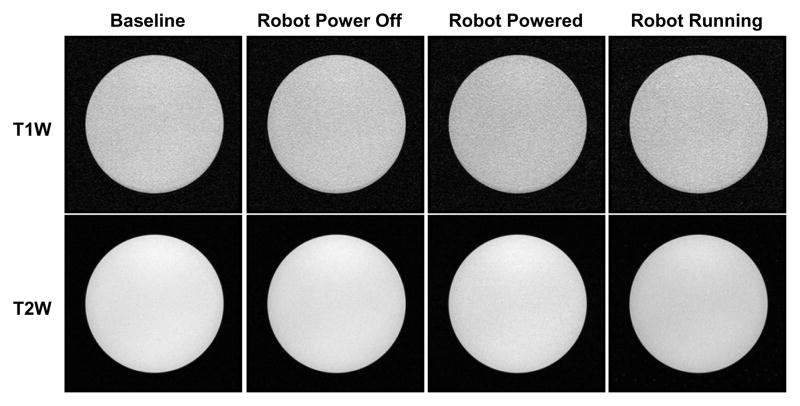
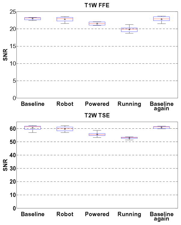
Five configurations of the robot were assessed to identify the root cause of image quality degradation: baseline with phantom only inside scanner, robot present but unpowered, robot powered, robot running during imaging, and then a repeated baseline with phantom only. Fig. 9 illustrates the representative images of SNR test with T1W-FFE and T2W-TSE images in the first four configurations. For the quantitative analysis, SNR is calculated as the mean signal in the center of the phantom divided by the noise outside the phantom. Mean signal is defined as the mean pixel intensity in the region of interest. The noise is defined as the average mean signal intensity in the four corners divided by 1.25 [26]. Fig. 10 shows the boxplot of the SNR for five robot configurations under these two scan protocols. The results from this plot are indicative of three primary potential sources of image artifact, namely materials of the robot (difference between baseline and robot present but unpowered), power system and wiring (difference between robot present but unpowered and robot powered), and drive electronics (difference between robot powered and robot running). The mean SNR reduction from baseline for these three differences are 2.78%, 6.30%, and 13.64% for T1W-FFE and 2.56%, 8.02% and 12.54% for T2W-TSE, respectively. Note that Fig. 9 shows this corresponding to visually unobservable image artifacts.
Fig. 9.
MRI of the homogeneous section of the phantom in four configurations with two imaging protocols demonstrating visually unobservable image artifacts.
Fig. 10.
Boxplots showing the range of SNR values for each of five robot configurations evaluated in two clinically appropriate neuro imaging protocols (T1W FFE & T2W TSE). The configurations include Baseline (no robotic system components present in room), Robot (robot presented but not powered), Powered (Robot connected to power on controller), Running (Robot moving during imaging), and a repeated baseline with no robotic system components present.
Elhawary et al. [24] demonstrated that SNR reduction for the same PiezoLegs motor (non-harmonic motor) using a commercially available driver is 26% with visually observable artifact. In terms of harmonic piezoelectric motors, Krieger et al. [12] showed that the mean SNR of baseline and robot motion using NanoMotion motors under T1W imaging reduced approximately from 250 to 50 (80%) with striking artifact. Though the focus of this paper is on the use of non-harmonic PiezoLegs motors for this application, we also demonstrated the control system capable of generating less than 15% SNR reduction for NanoMotion motors in our previous work [27]. Our system shows significant improvement with PiezoLegs motor over commercially available motor drivers when the robot is in motion. Even though there is no specific standard about SNR and image usability, the visually unobservable image artifact in our system is a key differentiator with that of [24] which used the same motors but still showed significant visual artifact.
2) Geometric Distortion based Compatibility Analysis
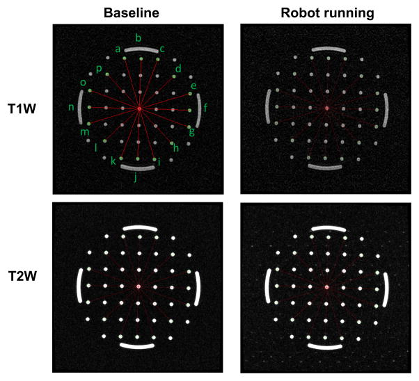
The NEMA standard (MS2-2008) defines 2D geometric distortion as the maximum percent difference between measured distances in an image and the actual corresponding phantom dimensions. Eight pairs of radial measurements (i.e. between points spanning the center of the phantom), are used to characterize the geometric distortion as shown in Fig. 11 for T1W-FFE and T2W-TSE protocols.
Fig. 11.
Geometric patterns of the non-homogeneous section of the phantom filled with pins and arches for the two extreme robot configurations and the same two imaging protocols. The overlaid red line segments indicates the measured distance for geometric distortion evaluation.
With the known geometry of the pins inside the phantom, the actual pin distance is readily available. The distance is measured on the image, and then are compared to the actual corresponding distances in the phantom as shown in Table. III for T1W-FFE protocol. The maximum difference between baseline image acquired with no robot and actual distance is less than 0.31% as shown in the third column of the table. The measured maximum distortion percentage for images acquired while the robot was running was 0.20%. This analysis demonstrates negligible geometric distortion of the acquired images due to the robot running during imaging.
TABLE III.
Geometric distortion evaluations under scan protocol T1W.
| Line segment | Actual distance (mm) | Measured distance (difference %) | |
|---|---|---|---|
| Baseline | Robot running | ||
| ai | 158.11 | 158.46(0.22) | 158.39(0.17) |
| bj | 150.00 | 150.46(0.31) | 150.24(0.16) |
| ck | 158.11 | 158.48(0.23) | 158.03(0.05) |
| dl | 141.42 | 141.51(0.07) | 141.14(0.20) |
| em | 158.11 | 157.97(0.09) | 157.85(0.17) |
| fn | 150.00 | 149.92(0.05) | 149.89(0.07) |
| go | 158.11 | 158.16(0.03) | 158.24(0.08) |
| hp | 141.42 | 141.65(0.16) | 141.65(0.16) |
3) Qualitative Imaging Evaluation
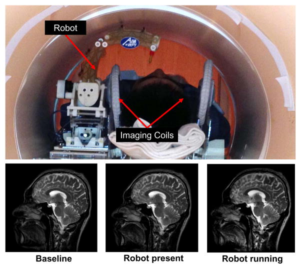
In light of the quantitative SNR results of the robot system, the image quality is further evaluated qualitatively by comparing brain images acquired with three different configurations under the previously defined T2W imaging sequence. Fig. 12 shows the experimental configuration and the corresponding brain images of a volunteer placed inside scanner bore with the robot. There is no visible loss of image quality (noise, artifacts, or distortion) in the brain images when controller and robot manipulator are running.
Fig. 12.
Qualitative analysis of image quality. Top: Patient is placed inside scanner bore with supine position and robot resides on the side of patient head. Bottom: T2 weighted sagittal images of brain taken with three configurations: no robot in the scanner (bottom-left), controller is powered but motor is not running (bottom-middle) and robot is running (bottom-right).
The capability to use the scanner’s real-time continuous imaging capabilities in conjunction with the robot to monitor needle insertion was further demonstrated. In one example qualitatively demonstrating this capability, a 21 Gauge Nitinol needle was inserted into a gelatin phantom under continuous updated images (700ms per frame). The scan parameters including the repetition rate can be adapted as required for the particular application to balance speed, field of view, and image quality. As shown in Fig. 13, the needle is clearly visible and readily identifiable in the MR images acquired during needle insertion, and these images are available in real-time for visualization and control. The small blobs observed near the needle tip in these images are most likely due to the shape of the needle tip geometry.
Fig. 13.
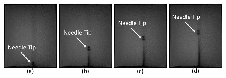
Example of real-time MR imaging capabilities at 1.4Hz during needle insertion. Shown at (a) Initial position, (b) 25mm depth, (c) 45mm depth, and (d) 55mm insertion depth into a phantom.
B. Robotic System Accuracy Evaluation
Assessing system accuracy was undertaken in two main phases: 1) benchtop free-space system accuracy and 2) MR image-guided system accuracy. Free-space accuracy experiment utilized an optical tracking system to calibrate and verify accuracy, while image-guided analysis utilized MR images. Three metrics are utilized for analyzing system error as summarized in Table IV from both experiments, i.e. tip position, insertion angle and distance from RCM intersection point to needle axes. Tip position error is a measure of the distance between a selected target and the actual location of the tip of the inserted cannula. Insertion angle error is measured as an angular error between the desired insertion angle and the actual insertion angle. Distance from RCM intersection point to needle axes represents an analysis of the mechanisms performance as an RCM device. For these measurements a single RCM point is targeted from multiple angles, and the minimum average distance from a single point of all the insertion axes is determined via least squares analysis. The actual tip positions, as determined via the OTS system during the benchtop experiment and image analysis for the MRI guided experiments, are registered to desired targets with point cloud based registration to isolate the robot accuracy from registration-related errors in the experiments.
TABLE IV.
Analysis of OTS and Image-Guided Accuracy Studies
| Tip Position (mm) | Distance from Needle Axes(mm) | Insertion Angle (Degree) | ||
|---|---|---|---|---|
|
| ||||
| Optical Tracker | Maximum Error | 1.56 | 0.44 | 3.07 |
|
|
||||
| Minimum Error | 0.48 | 0.22 | 0.90 | |
|
|
||||
| RMS Error | 1.09 | 0.33 | 2.06 | |
|
|
||||
| Standard Deviation | 0.28 | 0.05 | 0.76 | |
|
| ||||
| MRI-Guided | Maximum Error | 2.13 | 0.59 | 2.79 |
|
|
||||
| Minimum | 0.51 | 0.47 | 0.85 | |
|
|
||||
| RMS Error | 1.38 | 0.54 | 2.03 | |
|
|
||||
| Standard Deviation | 0.45 | 0.05 | 0.58 | |
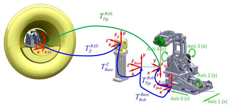
A fiducial-based registration is used to localize the base of the robot in the MRI scanner. To register the robot to the image space, the serial chain of homogeneous transformations is used, as show in Fig. 14.
Fig. 14.
Coordinate frames of the robotic system for registration of robot to MR image space
| (1) |
where is the needle tip in the RAS (Right, Anterior, Superior) patient coordinate system, is the Z-shaped fiducial’s coordinate in RAS coordinates, which is localized in 6-DOF from MR images via a Z-frame fiducial marker based on multi-image registration method as described in more detail by Shang et al. in [28]. The fiducial is rigidly fixed to the base and positioned near the scanner isocenter; once the robotic system is registered, this device is removed. Since the robot base is fixed in scanner coordinates, this registration is only necessary once. is is a fixed calibration of the robot base with respect to the fiducial frame, is the constant offset between robot origin and a frame defined on the robot base, and is the needle tip position with respect to the robot origin, which is obtained via the robot kinematics.
1) Robot Accuracy Evaluation with Optical Tracking System
A Polaris optical tracking system (Northern Digital Inc, Canada) is utilized, with a passive 6-DOF tracking frame attached to the robot base, and an active tracking tool mounted on the end-effector.
The experiment is a two step procedure, consisting of robot RCM mechanism calibration and robot end-effector positioning evaluation. The first procedure was performed by moving the mechanism through multiple orientations while keeping the Cartesian base fixed, and performing a pivot calibration to determine tool tip offset (RMS error of this indicates RCM accuracy). After successfully calibrating the RCM linkage, the robot is moved to six targets locations, with each target consisting of five different orientations. Three groups of data were recorded: desired needle tip transformation, reported needle transformation as calculated with kinematics based on optical encoders readings, and measured needle transformation from OTS. Analysis of experimental data indicates that the tip position error (1.09 ± 0.28 mm), orientation error (2.06 ± 0.76°), and the error from RCM intersection point to needle axes (0.33 ± 0.05 mm) as can be seen in Table IV.
2) Robot Accuracy Evaluation under MR Image-Guidance
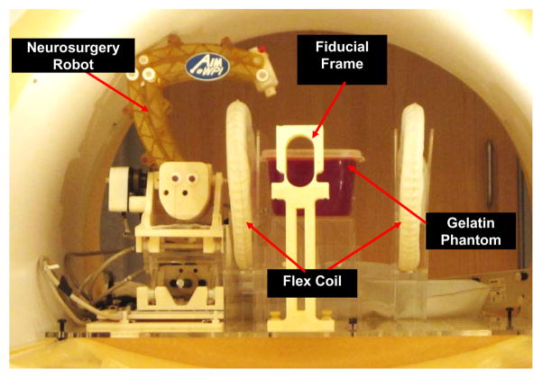
The experimental setup utilized to assess system level accuracy within the scanner is shown in Fig. 15. An 18-gauge ceramic needle (to limit paramagnetic artifacts) was inserted into a gelatin phantom and imaged with a high resolution 0.5mm3, T2-weighted turbo spin echo imaging protocol (T2W-TSE) to assess robot instrument tip position. This experiment reflects the effectiveness with which the robotic system can target an object identified within MR images. The experimental procedure is as follows:
Fig. 15.
Configuration of the robotic device within scanner bore for the MR image-guided accuracy study.
Initialize robot and image Z-frame localization fiducial;
Register robot base position with respect to RAS patient coordinates;
Remove fiducial frame and home robot;
Translate base to move RCM point to target location;
Rotate RCM axes to each of five insertion trajectories, insert ceramic needle, and image;
Retract needle and translate base axes to move RCM point to each of the new locations, and repeat;
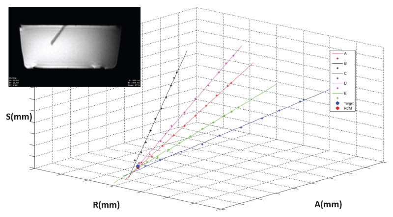
The insertion pathway (tip location and axis) of each needle insertion was manually segmented and determined from the MR image volumes, as seen in Fig. 16 for one representative target point. The best fit intersection point of the five orientations for each target location was found, both to determine the effectiveness of the RCM linkage as well as to analyze the accuracy of the system as whole. The results demonstrated an RMS tip position error of approximately 1.38 mm and an angular error of approximately 2.03° for the six targets, with an error among the varing trajectories from RCM intersection point to needle axes of 0.54 mm.
Fig. 16.
Plot of intersection of multiple insertion pathways at a given target location based on segmentation of the MRI data. Each axis is 40mm in length. Inset: MRI image of phantom with inserted ceramic cannula.
V. Discussion and Conclusion
This paper presents the first of its kind MRI-guided stereotactic neurosurgery robot with piezoelectric actuation that enables simultaneous imaging and intervention without affecting the imaging functionality. The contributions of this paper include: 1) novel mechanism design of a stereotactic neurosurgery robot, 2) piezoelectric motor control electronics that implements direct digital synthesis for smooth waveform generation to drive piezoelectric motors, 3) an integrated actuation, control, sensing and navigation system for MRI-guided piezoelectric robotic interventions, 4) image quality benchmark evaluation of the robotic system, and 5) targeting accuracy evaluation of the system in free space and under MR guidance.
Evaluation of the compatibility of the robot with the MRI environment in a typical diagnostic 3T MRI scanner demonstrates the capability of the system of introducing less than 15% SNR variation during simultaneous imaging and robot motion with no visually observable image artifact. This indicates the capability to visualize the tissue and target when the robot operates inside MRI scanner bore, and enables future fully-actuated system to control insertion depth and rotation while acquiring real-time images. Geometric distortion analysis demonstrated less than 0.20% image distortion which was no worse than that of baseline images without the robot present.
Targeting accuracy was evaluated in free space through benchtop studies and in a gelatin phantom under live MRI-guidance. The plastic material and manufacturing-induced errors result in the axes not being in perfect alignment relative to each other, and thus resulting in system error. 3D printed materials utilized in the construction of this device are very useful to rapidly create a mechanism for initial analysis, though upon disassembly, plastic deformation of the pivot locations for the parallelogram linkage were observed, and thought to have added to system inaccuracies; these parts would be machined from PEEK or Ultem in the clinical version of this system to improve stiffness and precision. In addition, large transmission distances on the two belt drive axes may be associated with angular inaccuracies.
This work aims to address three unmet clinical needs, namely efficiency, accuracy and safety. In terms of the efficiency, we compared the workflow of the current manual-frame approach and the MRI-guided robotic approach, revealing the potential to save 2–3 hours by avoiding an additional CT imaging session with associated CT-MRI fusion and the time-consuming localization method (i.e. microelectrode recording). In terms of the accuracy, MRI-guided needle placement accuracy experiment demonstrated 3-axis RMS error 1.38 ± 0.45 mm. The accuracy of traditional frame-based stereotaxy DBS with MRI guidance is 3.1 ± 1.41 mm for 76 stimulators implantation in human [2]. It is premature to corroborate the accuracy advantage of robotic approach due to the lack of clinical human trials. However, it shows the potential of the robotic approach to improve accuracy, by postulating that motorized solution is superior to the manual method. In terms of the safety, since the intraoperative brain anatomy, targets, and interventional tool are all visible with MR during the intervention, this enables compensation for brain shift and complete visualization of the interventional site during the procedure. Qualitatively, image-guidance is empowered with the obvious advantages over the indirect method (i.e. microelectrode recording) which is iterative, time-consuming, and unable to visualize any anatomy.
The currently intended application of the system is for DBS electrode placement. But as a generic MRI-compatible motion control system, this platform has the capability to be extended for other neurosurgical procedures (e.g. brain tumor biopsy and ablation) with different interventional tools. Further experiments include validation of the procedure time and targeting errors with cadaver and animal studies, aiming to improve the patient outcome as the final goal.
Acknowledgments
This work is supported in part by the National Institutes of Health (NIH) R01CA166379 and Congressionally Directed Medical Research Program (CDMRP) W81XWH-09-1-0191. The content is solely the responsibility of the authors and does not necessarily represent the official views of NIH or CDMRP.
Biographies
 Gang Li received the B.S. degree and M.S. degree in Mechanical Engineering from Harbin Institute of Technology, Harbin, China, in 2008 and 2011, respectively. He is currently a Doctoral Candidate in the Department of Mechanical Engineering at Worcester Polytechnic Institute, Worcester, MA. His research interests include medical robotics, robot mechanism design, MRI-guided percutaneous intervention, and needle steering.
 Hao Su received the B.S. degree from the Harbin Institute of Technology and M.S. degree from the State University of New York University at Buffalo, and Ph.D. degree from the Worcester Polytechnic Institute. He was a recipient of the Link Foundation Fellowship and Dr. Richard Schlesinger Award from American Society for Quality. His current research interests include surgical robotics and haptics. Currently, he is a research scientist at Philips Research North America, Briarcliff Manor, NY.
 Gregory Cole received his B.S. and M.S. degree in Mechanical Engineering, Ph.D. degree in Robotic Engineering, all from Worcester Polytechnic Institute. He was a George I. Alden Research Fellow at Worcester Polytechnic Institute in the Automation and Interventional Medicine Laboratory. Currently, he is a research scientist at Philips Research North America, Briarcliff Manor, NY.
 Weijian Shang received his B.S. degree in mechanical engineering from Tsinghua University in 2009 in Beijing. He also received his M.S. degree in mechanical engineering from Worcester Polytechnic Institute in 2012. He is currently a Graduate Research Assistant in Automation and Interventional Medicine Laboratory and is working towards his Ph.D. degree in mechanical engineering. He focuses on development of teleoperated MRI guided medical robot, force sensing and registration method.
 Kevin Harrington received his B.S. degree in Robotic Engineering from Worcester Polytechnic Institute. His research interests include embedded systems, software system architecture, and programming.
 Alex Camilo received the B.S. degree in Electrical and Computer Engineering from Worcester Polytechnic Institute of Technology, Worcester, MA, in 2010. His research interests include embedded communications protocols, MRI-guided robot, and PCB Design.
 Julie Pilitsis MD, PhD graduated from Albany Medical College. She completed her residency at Wayn State University, during which time she also obtained a PhD in neurophysiology. She then served as director of functional neurosurgery at UMass Memorial Medical Center, but has recently returned to Albany Medical College as an associate professor. Her research focuses on Functional Neurosurgery, including DBS for chronic pain.
 Gregory Fischer PhD is an Associate Professor of Mechanical Engineering with appointments in Biomedical Engineering and Robotics Engineering at Worcester Polytechnic Institute. He received B.S. degrees in Electrical Engineering and Mechanical Engineering from Rensselaer Polytechnic Institute, Troy, NY, in 2002 and an M.S.E. degree in Electrical Engineering from Johns Hopkins University, Baltimore, MD, in 2004. He received his Ph.D. degree in Mechanical Engineering from The Johns Hopkins University in 2008. Dr. Fischer is Director of the WPI Automation and Interventional Medicine Laboratory, where his research interests include development of robotic systems for image-guided surgery, haptics and teleoperation, robot mechanism design, surgical device instrumentation, and MRI-compatible robotic systems.
Contributor Information
Gang Li, Automation and Interventional Medicine Laboratory, Worcester Polytechnic Institute, Worcester, MA, USA.
Hao Su, Email: haosu.ieee@gmail.com, Philips Research North America, NY, USA and were with the Automation and Interventional Medicine Laboratory, Worcester Polytechnic Institute, MA, USA.
Gregory A. Cole, Philips Research North America, NY, USA and were with the Automation and Interventional Medicine Laboratory, Worcester Polytechnic Institute, MA, USA.
Weijian Shang, Automation and Interventional Medicine Laboratory, Worcester Polytechnic Institute, Worcester, MA, USA.
Kevin Harrington, Automation and Interventional Medicine Laboratory, Worcester Polytechnic Institute, Worcester, MA, USA.
Alex Camilo, Automation and Interventional Medicine Laboratory, Worcester Polytechnic Institute, Worcester, MA, USA.
Julie G. Pilitsis, Neurosurgery Group, Albany Medical Center, Albany, NY, USA
Gregory S. Fischer, Email: gfischer@wpi.edu, Automation and Interventional Medicine Laboratory, Worcester Polytechnic Institute, Worcester, MA, USA.
References
- 1.Hartkens T, Hill D, Castellano-Smith A, Hawkes D, Maurer C, Martin A, Liu H, Truwit C. Measurement and analysis of brain deformation during neurosurgery. Medical Imaging, IEEE Transactions on. 2003;22:82–92. doi: 10.1109/TMI.2002.806596. [DOI] [PubMed] [Google Scholar]
- 2.Starr PA, Martin AJ, Ostrem JL, Talke P, Levesque N, Larson PS. Subthalamic nucleus deep brain stimulator placement using high-field interventional magnetic resonance imaging and a skull-mounted aiming device: technique and application accuracy. Journal of Neurosurgery. 2010;112(3):479–490. doi: 10.3171/2009.6.JNS081161. [DOI] [PMC free article] [PubMed] [Google Scholar]
- 3.Larson P, Starr PA, Ostrem JL, Galifianakis N, Palenzuela MSL, Martin A. 203 application accuracy of a second generation interventional MRI stereotactic platform: initial experience in 101 DBS electrode implantations. Neurosurgery. 2013;60:187. [Google Scholar]
- 4.Varma T, Eldridge P, Forster A, Fox S, Fletcher N, Steiger M, Littlechild P, Byrne P, Sinnott A, Tyler K, et al. Use of the NeuroMate stereotactic robot in a frameless mode for movement disorder surgery. Stereotactic and functional neurosurgery. 2004;80(1–4):132–135. doi: 10.1159/000075173. [DOI] [PubMed] [Google Scholar]
- 5.Masamune K, Kobayashi E, Masutani Y, Suzuki M, Dohi T, Iseki H, Takakura K. Development of an MRI-compatible needle insertion manipulator for stereotactic neurosurgery. Journal of Image Guided Surgery. 1995;4:242–248. doi: 10.1002/(SICI)1522-712X(1995)1:4<242::AID-IGS7>3.0.CO;2-A. [DOI] [PubMed] [Google Scholar]
- 6.Lang M, Greer A, Sutherland G. Intra-operative robotics: NeuroArm. Intraoperative Imaging. 2011;109:231–236. doi: 10.1007/978-3-211-99651-5_36. [DOI] [PubMed] [Google Scholar]
- 7.Ho M, McMillan A, Simard J, Gullapalli R, Desai J. Toward a meso-scale SMA-actuated MRI-compatible neurosurgical robot. Robotics, IEEE Transactions on. 2012 Feb;28:213–222. doi: 10.1109/TRO.2011.2165371. [DOI] [PMC free article] [PubMed] [Google Scholar]
- 8.Comber DB, Barth EJ, Webster RJ. Design and control of an magnetic resonance compatible precision pneumatic active cannula robot. Journal of Medical Devices. 2014;8(1):011003. [Google Scholar]
- 9.Yang B, Tan UX, McMillan A, Gullapalli R, Desai J. Design and control of a 1-dof MRI-compatible pneumatically actuated robot with long transmission lines. Mechatronics, IEEE/ASME Transactions on. 2011;16(6):1040–1048. doi: 10.1109/TMECH.2010.2071393. [DOI] [PMC free article] [PubMed] [Google Scholar]
- 10.Liao H, Inomata T, Sakuma I, Dohi T. 3-D augmented reality for MRI-guided surgery using integral videography autostereoscopic image overlay. Biomedical Engineering, IEEE Transactions on. 2010 Jun;57:1476–1486. doi: 10.1109/TBME.2010.2040278. [DOI] [PubMed] [Google Scholar]
- 11.Hirai N, Kosaka A, Kawamata T, Hori T, Iseki H. Image-guided neurosurgery system integrating AR-based navigation and open-MRI monitoring. Computer Aided Surgery. 2005;10(2):59–72. doi: 10.3109/10929080500229389. [DOI] [PubMed] [Google Scholar]
- 12.Krieger A, Song SE, Cho N, Iordachita I, Guion P, Fichtinger G, Whitcomb L. Development and evaluation of an actuated MRI-compatible robotic system for MRI-guided prostate intervention. Mechatronics, IEEE/ASME Transactions on. 2013;18(1):273–284. doi: 10.1109/TMECH.2011.2163523. [DOI] [PMC free article] [PubMed] [Google Scholar]
- 13.Fischer GS, Iordachita I, Csoma C, Tokuda J, DiMaio SP, Tempany CM, Hata N, Fichtinger G. MRI-compatible pneumatic robot for transperineal prostate needle placement. Mechatronics, IEEE/ASME Transactions. 2008;13(3):295–305. doi: 10.1109/TMECH.2008.924044. [DOI] [PMC free article] [PubMed] [Google Scholar]
- 14.Stoianovici D, Kim C, Srimathveeravalli G, Sebrecht P, Petrisor D, Coleman J, Solomon S, Hricak H. MRI-safe robot for endorectal prostate biopsy. Mechatronics, IEEE/ASME Transactions on. 2014;PP(99):1–11. doi: 10.1109/TMECH.2013.2279775. [DOI] [PMC free article] [PubMed] [Google Scholar]
- 15.Chinzei K, Miller K. MRI guided surgical robot. Australian Conference on Robotics and Automation; 2001. pp. 50–55. [Google Scholar]
- 16.Tsekos N, Khanicheh A, Christoforou E, Mavroidis C. Magnetic resonance-compatible robotic and mechatronics systems for image-guided interventions and rehabilitation: a review study. Annual Review of Biomedical Engineering. 2007;9:351–387. doi: 10.1146/annurev.bioeng.9.121806.160642. [DOI] [PubMed] [Google Scholar]
- 17.Gassert R, Burdet E, Chinzei K. Opportunities and challenges in MR-compatible robotics. Engineering in Medicine and Biology. 2008;3:15–22. doi: 10.1109/EMB.2007.910265. [DOI] [PubMed] [Google Scholar]
- 18.Cole GA, Pilitsis JG, Fischer GS. Design of a robotic system for MRI-guided deep brain stimulation electrode placement. IEEE Int Conf on Robotics and Automation; May 2009. [Google Scholar]
- 19.Cole G, Harrington K, Su H, Camilo A, Pilitsis J, Fischer G. Closed-loop actuated surgical system utilizing real-time in-situ MRI guidance. International Symposium on Experimental Robotics; 2010. [Google Scholar]
- 20.Hata N, Piper S, Jolesz FA, Tempany CM, Black PM, Morikawa S, Iseki H, Hashizume M, Kikinis R. Application of open source image guided therapy software in MR-guided therapies. International Conference on Medical Image Computing and Computer Assisted Intervention (MICCAI) 2007;10:491–498. doi: 10.1007/978-3-540-75757-3_60. [DOI] [PubMed] [Google Scholar]
- 21.Tokuda J, Fischer GS, Papademetris X, Yaniv Z, Ibanez L, Cheng P, Liu H, Blevins J, Arata J, Golby AJ, et al. Openigtlink: an open network protocol for image-guided therapy environment. The International Journal of Medical Robotics and Computer Assisted Surgery. 2009;5(4):423–434. doi: 10.1002/rcs.274. [DOI] [PMC free article] [PubMed] [Google Scholar]
- 22.Fischer G, Iordachita I, Csoma C, Tokuda J, DiMaio S, Tempany C, Hata N, Fitchinger G. MRI-compatible pneumatic robot for transperineal prostate needle placement. Mechatronics, IEEE/ASME Transactions on. 2008;13:295–305. doi: 10.1109/TMECH.2008.924044. [DOI] [PMC free article] [PubMed] [Google Scholar]
- 23.Yu N, Gassert R, Riener R. Mutual interferences and design principles for mechatronic devices in magnetic resonance imaging. International Journal of Computer Assisted Radiology and Surgery. 2011;6(4):473–488. doi: 10.1007/s11548-010-0528-2. [DOI] [PubMed] [Google Scholar]
- 24.Elhawary H, Zivanovic A, Rea M, Davies B, Besant C, McRobbie D, de Souza N, Young I, Lamprth M. The feasibility of MR-image guided prostate biopsy using piezoceramic motors inside or near to the magnet isocentre. International Conference on Medical Image Computing and Computer Assisted Intervention (MICCAI) 2006;9:519–526. doi: 10.1007/11866565_64. [DOI] [PubMed] [Google Scholar]
- 25.Young JW. Technical Information Center Document. 1993. Head and face anthropometry of adult US civilians. [Google Scholar]
- 26.Determination of Signal-to-Noise Ratio (SNR) in Diagnostic Magnetic Resonance Imaging, NEMA Standard Publication MS 1-2008. The Association of Electrical and Medical Imaging Equipment Manufacturers; 2008. [Google Scholar]
- 27.Fischer G, Cole G, Su H. Approaches to creating and controlling motion in MRI. Engineering in Medicine and Biology Society, EMBC, Annual International Conference of the IEEE; 2011. pp. 6687–6690. [DOI] [PubMed] [Google Scholar]
- 28.Shang W, Fischer GS. A high accuracy multi-image registration method for tracking MRI-guided robots. SPIE Medical Imaging. 2012 Feb; [Google Scholar]


