Abstract
Hepatocellular carcinoma annually affects over 700,000 people worldwide and trends indicate increasing prevalence. Patients ineligible for surgery undergo loco-regional treatments such as transarterial chemoembolization (TACE) to selectively target tumoral blood supply. Using a microcatheter, chemotherapeutics are infused followed by an embolic agent, or the drug is encapsulated by the embolic moiety; simultaneously inducing stasis while delivering localized chemotherapy. Presently, several products are used, but no universally accepted system is promoted because very disparate limitations exist. The goal of this investigation was to design and develop in situ gelling recombinant silk-elastinlike protein polymers (SELPs) for TACE. Two SELP compositions, SELP-47K and SELP-815K, with varying lengths of silk and elastin blocks, were investigated to formulate a new embolic that was injectable through commercially available microcatheters. The goal was to develop a composition providing maximal permeation of tumor vasculature while exhibiting effective embolic activity. The SELPs evaluated remain soluble until reaching 37°C, when irreversible tran sition ensues forming a solid hydrogel network. SELP-815K formulated at 12% w/w with shear processing demonstrated acceptable rheological properties and clear embolic capability under flow conditions in vitro. A rabbit model showed feasibility of embolization in vivo allowing selective occlusion of lobar hepatic arterial branches.
Keywords: embolization, TACE, recombinant polymers, hepatocellular carcinoma
1. Introduction
Embolic agents are frequently used in interventional radiology procedures, and particularly in transarterial embolization treatments of hypervascular tumors. Primary hepatocellular carcinoma (HCC) is one such malignancy, with an annual world-wide incidence of over half a million cases [1]. Despite advances in treatment, HCC remains the third leading cause of cancer-related deaths [2–9]. Treatment selection is directed by the stage of cancer and availability of expertise [2]. Surgical resection in early stage disease with well-preserved liver function may be curative. Less than 30% of the patients fall into this category, and the surgical therapies achieve a 5 year survival ranging 50–75% [6, 9–11]. For the remaining patients, non-curative palliative care or bridge-to-transplant treatments are implemented to improve survival. These include transarterial embolization, and more specifically transarterial chemoembolization (TACE). TACE involves selective access of hepatic arteries supplying the tumor, and administration of a combination of chemotherapeutic and embolic agent to reduce tumoral blood supply and induce necrosis [12, 13]. This ability to selectively deliver chemotherapeutic agents allows for a reduction in side effects and preservation of healthy surrounding tissue, while maintaining treatment efficacy.
Biomaterials used in these procedures widely vary region-to-region on a global scale [14, 15]. A presently approved product, Lipiodol®, is a radiopaque ethiodized oil mixed with a chemotherapeutic creating an emulsion often used in conjunction with gelatin particles or synthetic polymer beads, which act as embolics [7, 13, 16]. The oily emulsion penetrates the vasculature, with higher retention levels in HCC as compared to healthy hepatic tissue [13]. The liquid nature allows permeation down to the capillary level, affording more extensive drug exposure. However, the duration of drug release is short (days), and follow-up treatments are not optimal due to the vessel occlusion from the first treatment. Drug eluting beads (DEBs) are now gaining favor for this procedure, replacing the multistep oil emulsion system. These beads provide localized sustained drug release up to 30 days while reducing arterial blood inflow and reducing washout of the chemotherapeutic. However, they too have shortcomings, i.e., aggregation of smaller diameter beads, off target embolization particularly in pulmonary circulation and in the kidneys, elution of only charged small molecule therapeutics, non-degradability, and limited tumor depth penetration [15, 17].
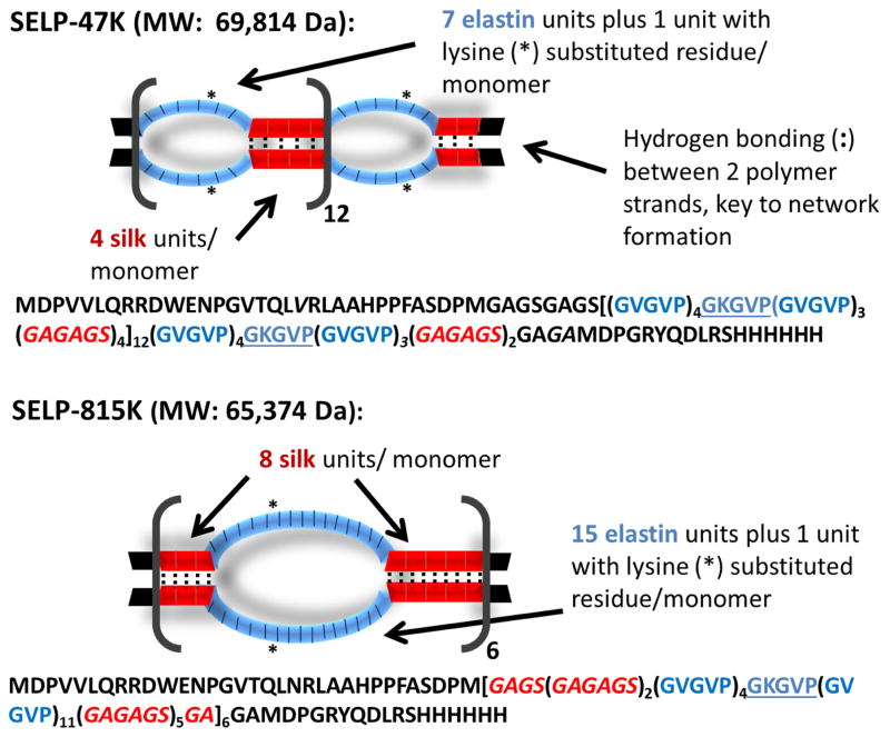
To address limitations of both systems, recombinant silk-elastinlike protein polymer (SELP) formulations that are injectable as a liquid at room temperature, therefore capable of accessing smaller caliber vessels like Lipiodol®, then transitioning into a solid hydrogel at 37°C capable of occlusion and drug delivery like the DEBs, were investigated. Recombinant polymers offer versatile material platforms in which function can be achieved through precise design of sequence and length. SELPs are a family of genetically engineered protein polymers capable of broad range drug release and tunable physicochemical properties and degradability [18–21]. SELPs are block copolymers consisting of silk-like and elastin-like units. Two compositions, SELP-47K and SELP-815K (Fig. 1) were chosen for this evaluation based on our previous work showing appropriate solubility, solution stability, injectability, gelation rate, and gel strength [18, 19, 22]. Both of these polymers remain soluble in aqueous solution at room temperature and begin to gel as the temperature is raised to 37°C. At this temperature, gelation can occur within minutes. The rate of gelation is dependent on the concentration of the SELP and the level of shear processing the protein experiences prior to use [23]. SELP-47K and SELP-815K have similar molecular weights and silk to elastin compositional ratio (1:2), but lengths of the silk and elastin blocks per repeat are doubled in SELP-815K compared to SELP-47K. The use of multiple SELPs allows examination of the dependency of TACE performance on sequence and compositional difference of the selected polymers. The SELP embolic was qualified on the basis of two primary performance criteria.
Fig. 1. Diagram of SELP-47K and SELP-815K protein polymers (single letter amino acid abbreviations are used).
The silk-like block, GAGAGS, is represented in red and the elastin-like block, GVGVP, is represented in blue. While the overall content of silk and elastin-like blocks between SELP-47K and SELP-815K are comparable (approximately 1:2), SELP-815K has twice the number of silk and elastin-like blocks per repeat. When in alignment between strands, the silk repeats form beta sheets via hydrogen bonding. Because the silk repeats are twice longer in SELP-815K, they have twice the potential for formation of hydrogen bonds within each repeat. Greater numbers of hydrogen bonds results in stronger network formation and a stronger gel.
The SELP composition had to be injectable through a commercially available microcatheter and had to occlude an in vitro model tumor of an arterio-capillary bed under simulated blood flow conditions. Following in vitro testing, the formulation showing highest efficacy was then tested in vivo, using a rabbit model.
2. Materials and Methods
2.1. Materials
SELP-47K and SELP-815K were synthesized and characterized as previously described [18, 19, 22]. C5 Emulsilex was purchased from Avestin (Ottawa, ON) and modified using high pressure valves and fittings from Autoclave Engineers (Erie, PA). Merit Maestro® Microcatheters, guide wire torque devices, and arterial access kits were donated by Merit Medical Systems (South Jordan, UT). 0.018″ Nitinol Mandrel Wire guidewires from GALT Medical (Garland, TX) were used.
2.2. Design and fabrication of model microfluidics device
A biomimetic vasculature design was made using AutoCAD software based on the Murray-Hess law of minimal work [24–26]. Size of the arterio-capillary bed was based on the average tumor size in patients with intermediate HCC, a diameter of 4–6 cm. Lithography techniques were used to create a silicon wafer mold for fabrication of devices out of PDMS (Sylgard 184, Dow Corning). PDMS was prepared at a ratio of 10:1 PDMS to curing agent (part of Sylgard kit), and the mixture poured over the mold and into a petri dish for the device backing. The molds were cured in an oven at 65°C for an hour. Inlet and outlet ports were cored out of the backing side of the device sandwich using a 1.5 mm biopsy punch. Next, the PDMS piece retaining the channels design and the flat PDMS backing were corona plasma treated, oxidizing the surface and sandwiched together to create the final device. The seal was tested by injecting a dye solution at a series of pressures.
2.3. Formulation development
SELP formulations were made up in 1X phosphate buffered saline (PBS) and concentrations were calculated based on weight. Lyophilized protein for a predetermined concentration was weighed and slowly added to chilled PBS in a 1.7 mL snapseal graduated microtube (GeneMate), while vortexing. The sample was transferred to ice every 30 seconds to maintain low temperatures. Once fully reconstituted, the sample was flash frozen in liquid nitrogen and stored at -80°C until use. Samples prepared for in vivo testing were made using sterile, pyrogen-free PBS (Life Technologies) and using aseptic technique. The in vivo formulations were stored in capped sterile 1 mL syringes (BD Medical) or CryoFreeze cell culture tubes (GeneMate).
2.4. Rheological characterization
Rheological testing was carried out with an AR 550 stress-controlled rheometer from TA Instruments (New Castle, DE) using a steel 20 mm diameter, 4 degree cone-and-plate configuration. Characterization consisted of viscosity testing, carried out using an oscillation procedure with a temperature ramp from 18°C to 37°C at an angular frequency of 6.283 rad/s, followed by an oscillatory time sweep of 5 hrs at 37°C, angular frequency of 6.283 rad/s, and 0.1% strain measuring dynamic viscoelastic moduli G′ and G″, the storage and loss moduli respectively. Individual samples previously prepared and stored frozen were thawed just before use in 18–23°C water and centrifuged at 14,000 rpm in a Centrifuge 5417C (Eppendorf) for 45 seconds to remove bubbles. 150μL immediately was transferred to the Peltier plate, at 18°C. Measurements were conducted in triplicate.
2.5. Shearing and contrast incorporation
Shear processing was performed using an Avestin C5 Emulsiflex homogenizer custom modified with a high pressure needle valve fitted with a 3-way Luer-Lok stopcock. Stainless steel parts contacting the sample were depyrogenated prior to use with 0.5 M sodium hydroxide and rinsed with depyrogenated water and PBS. Samples were prepared just prior to processing via reconstitution of lyophilized protein at a predetermined concentration in 1X chilled PBS as previously described. To maintain low temperatures, the homogenizer was submerged in an ice bath. After transferring the polymer sample into the sample cylinder, nitrogen gas was used to pressurize the chamber to 80psi. Slowly opening the homogenizing valve, the sample flowed into the pump body chamber where the motor pump generated 17,000 psi sending the sample through the needle valve and collected into sterile 1 mL syringes (BD Medical). Collected samples were either aliquoted into 1.8 mL CryoFreeze tubes (GeneMate) or the syringes were capped and immediately flash frozen in liquid nitrogen and stored at -80°C. For in vivo studies, iso-osmolar contrast dye, Visipaque™ 320 (GE Healthcare), was added during the reconstitution step to 20% by weight and the formulation was sheared as described above.
2.6. In vitro testing of polymer candidate
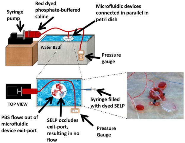
To mimic the low blood pressure of the hepatic system, the in vitro setup consisted of a syringe pump delivering warmed PBS at 3.4 mL/min via silicone tubing into three fabricated microfluidic devices linked in parallel and partially submerged in a water bath set to 37°C. A pressure gauge monitored the overall pressure, and a temperature probe monitored the internal temperature of the device. During flow, the pressure was maintained below 1 psi. The device chosen for occlusion testing had a second port for the microcatheter. The microcatheter was submerged in the water bath to equilibrate to temperature. 1 mL of the SELP candidate formulation was manually injected using a 1 mL syringe (BD Medical) over 30 seconds.
2.7. In vivo feasibility testing of polymer candidate
Hepatic embolization was conducted in male New Zealand white rabbits (4–4.5 kg body weight) to verify the occlusive ability of the candidate SELP formulation in vivo. The procedural protocol was approved by IACUC and conducted in accordance with all applicable regulations. The surgical procedure consisted of anesthetizing the animal and exposing the right femoral artery via a surgical cutdown. Arterial access was obtained with a radial artery line kit. 2% lidocaine (Vetone) was dripped onto the vessel to prevent spasm during needle and sheath insertion. The microcatheter was advanced under fluoroscopic guidance using a OEC/GE Series 9800 Mobile C-arm (GE Healthcare, Little Chalfont, UK) up the femoral artery and aorta into the celiac trunk. Depending on the size of vessels and the anatomical variation, the catheter was maneuvered up the common hepatic artery, into the proper hepatic artery, and if vessel diameter permitted, either the left or right hepatic artery. Visipaque™ 320 contrast dye was used to visualize the vessels. Following identification of the vessel, a 1 mL syringe of the sheared 12% w/w SELP-815K containing 20% w/w Visipaque™ 320 was thawed, centrifuged (Forma 400 ML GP Centrifuge, Thermo Electron Corp.) for 45 seconds to remove bubbles, and manually injected under fluoroscopic visualization. Following injection, a volume of sterile saline equivalent to the holdup volume of the catheter (0.6 mL) was injected to expel the SELP from the catheter. 5 minutes was allotted for gel formation, after which contrast dye was injected to determine the level of occlusion. Another 5 minutes was allotted, followed by a second contrast injection, to ensure the SELP embolus remained lodged. Following imaging, the animal was euthanized. For a histological control, one animal underwent the entire procedure except it was injected with saline only. Each of the three test animals had a pre-injection contrast angiogram showing flow, thus acting as a control prior to SELP injection. The procedures were conducted by an interventional radiologist who specializes in TACE procedures.
2.8. Histological analysis
Liver and lungs of each animal were immediately fixed in 10% buffered formalin for 48 hrs and then transferred to 70% ethanol. Sections from each liver lobe and each lung lobe were cut in 5 μm slices and analyzed. Tissue samples were stained using both hematoxylin and eosin (H&E) stain and an immunohistochemistry (IHC) stain specific for SELP using an antibody for poly-Histidine (anti-6X His tag®, Abcam, Cambridge, MA; 1:3000 dilution), which is found in the carboxyl-terminal sequence of the SELP polymer strand. A chromogenic detection was used, IView diaminobenzidine research detection kit (Ventana Medical Systems) and hematoxylin counterstain (Ventana Medical Systems) in the IHC procedure. A piece of pre-gelled SELP was fixed, sliced, mounted onto a slide, and stained as a positive control using both stains. Slides were imaged using a Nikon DXM 1200C Digital Camera affixed to an Olympus BH2 microscope and analyzed in ACT-1C for DXM1200C software.
2.9. Statistical analysis
All experiments were conducted in triplicate and data is presented as the mean ± standard error of the mean unless specified otherwise. For the rheological traces of the moduli, the raw data was processed using a rolling average of ten points to minimize noise, particularly in the slower gelling formulations. Significance between multiple groups was determined using a one-way analysis of variance (ANOVA) with a Tukey’s posttest, and a two tailed Student’s t-test was used for comparing pairs of data. Significance was reported as p<0.05, highly significant when p<0.01, and very highly significant when p<0.001.
3. Results
3.1. Design and fabrication of model microfluidics device
The goal of the model design was to mimic the microcirculation of vessels feeding a hepatic tumor, particularly arterioles, which range in size from 10–100 μm. Using the Murray-Hess law as a guideline for calculating the channel widths of daughter branches, the entry branch was 1000 μm in width, branching down consecutively until reaching central channels 50 μm in width (see supplementary Fig. S1). Size and geometry of the channels were limited by the loft lithography technique used to create the device mold. Channel height was 100 μm throughout the entire length of the device. The in vitro microfluidics device provided a method to create a system where overall pressure drops as the total area increases with each branch point. This idea was verified when multiple devices were connected in a parallel circuit, representing acini in a liver lobe, and the overall pressure dropped from an average of 5.6 ± 0.7 (SD) psi when a single device was attached to 4 psi when two were connected and then down to 0 psi when three were connected in parallel. Sensitivity of the pressure gauge was not high enough to determine pressures between 0 and 1 psi. Fabricated devices were all checked with dye colored water for any potential leaks prior to use in the in vitro experiments.
3.2. Formulation development
The viscosity, gelation time, and mechanical properties of SELPs not only depend on the composition of the polymer sequence, but also on the concentration of the polymer solution and its shear processing. Target specifications for the maximum viscosity, the maximum gelation time and the minimum gel stiffness were defined either experimentally or empirically. The maximum viscosity able to be injected through a commercial microcatheter was determined to be 150 cP, using silicone oil standards (Brookfield). The maximum gelation time was set at 5 minutes to allow enough time for injection, but short enough for the gel to set prior to venous washout. A minimum gel stiffness at 5 hours of 1E5 Pa was set based on empirical evidence. Testing of formulations began with 16% w/w (weight percent) of SELP-47K and -815K, the maximum solubility for each polymer. The lyophilized polymers were reconstituted in PBS and immediately underwent rheological testing. Evaluations continued with polymer concentrations of 14 and 12% w/w. Shearing was evaluated for its effect in improving gelation time and final gel stiffness. In this case, sheared formulations were processed and frozen in liquid nitrogen prior to thawing and testing.
3.3. Rheological characterization and finalization of candidate formulation
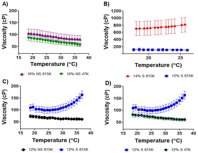
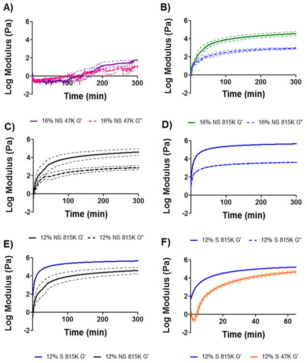
Each rheological run consisted of a viscosity measurement followed by a 5 hr oscillatory trace of the polymer sample to measure the viscoelastic moduli, G′ and G″. Formulations were evaluated by comparing the sol/gel transition point (the crossover point of G′ and G″) and the gel stiffness at 5 hr (G′ plateau). A viscosity specification was set based on the injectability of silicone oil standards through tubing of inner diameters similar to clinical microcatheters. In the injection temperature window of 18–25 °C, the maximum injectable viscosity was 150 cP. As a reference, Lipiodol® viscosity at 20°C is 34–70 cP. The first formulations tested were 16% w/w SELP-47K and SELP-815K (both with no shear processing). Viscosity of the formulations remained well below the specified value (Fig. 2A). However, the oscillatory traces (Fig. 3A and B) demonstrated insufficient gel time and mechanical properties. Non-sheared 16% w/w SELP-47K required over 100 minutes to reach its gel point, G′>G″, and the final gel stiffness at 5 hours (5.9E1 Pa) was orders of magnitude less than the specified value (1E5 Pa). Compared to SELP-47K, the non-sheared 16% w/w SELP-815K reached its gel point faster (3.5 minutes) and achieved a greater gel stiffness at 5 hours (3.7E4 Pa); however, the gel stiffness did not meet the specified value either.
Fig. 2. Viscosity traces of candidate polymer compositions.
The maximum viscosity target of 150 centipoise (cP) was specified to permit a formulation to be injectable through a commercially available 2.8F microcatheter. Viscosities were measured between 18 and 37°C, representing the injecting temperature range. A) 16% w/w formulations of reconstituted lyophilized polymer non-sheared (NS) of both SELP-47K (47K) and SELP-815K (815K) remained below 150cP. B) 14% w/w sheared SELP-815K began to gel upon thawing the sample and the viscosity was above the specification. Reduction to 12% w/w sheared SELP-815K provided appropriate viscosity. C) Comparison of non-sheared and sheared 12% w/w SELP-815K. 12% sheared (S) SELP-815K showed increasing viscosity as a result of network formation but the viscosity remained in the injectable range. D) Comparison of 12% w/w sheared SELP-815K and SELP-47K. The lack of increasing viscosity with increasing temperature by 12% w/w sheared SELP-47K indicated slower network formation. For all traces n=3 ± SEM.
Fig. 3. Rheological characterization of candidate polymer compositions.
The shear storage modulus, G′, and the shear loss modulus, G″, were measured and used to assess time to gel formation and final gel stiffness over 5hrs. Panels A–D provide G′/G″ traces of candidate compositions. Panel E compares G′ of sheared and non-sheared 12% w/w SELP-815K, showing the effect of shear processing on final gel stiffness. Panel F shows the difference in rate of gelation between 12% w/w sheared SELP-815K and 12% w/w sheared SELP-47K; the faster gelation by 12% w/w sheared SELP-815K finalized the selection of this candidate to move into in vitro testing. All traces n=3 ± SEM.
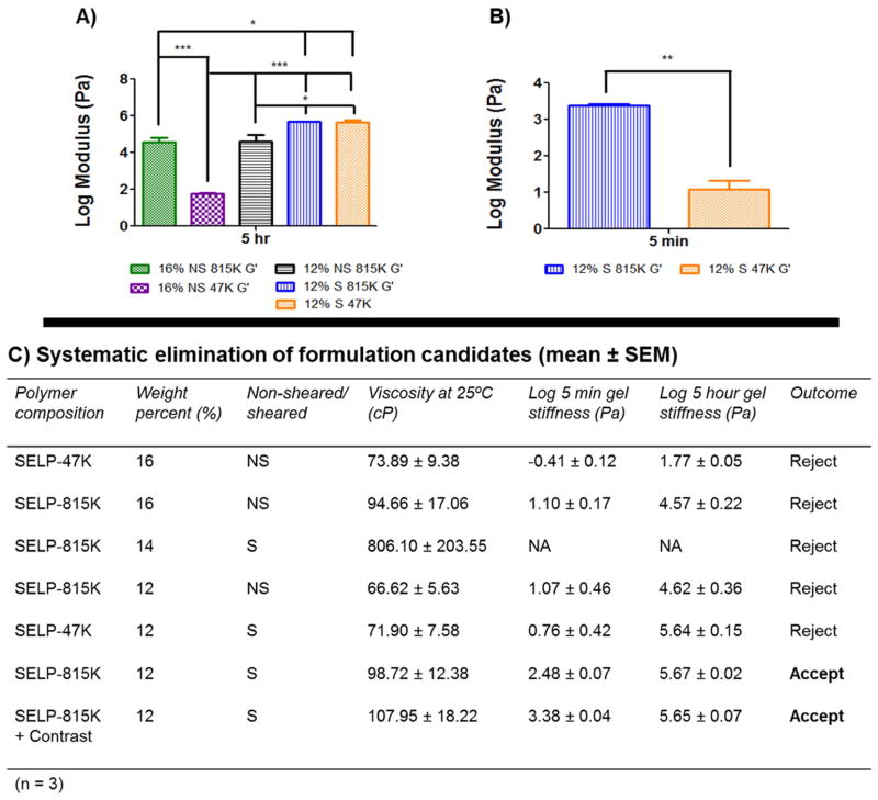
With these results, the SELP-815K formulation underwent shear processing. As expected, shearing caused a dramatic increase in gelation. Shearing of the 16% w/w SELP-815K caused the material to immediately gel. At 14% w/w, SELP-815K still gelled at room temperature prior to freezing and storage and the viscosity was nearly 700cP at the outset and rose with increasing temperature (Fig. 2B). The SELP-815K concentration was reduced further to 12% w/w and the formulation was tested and compared both with non-sheared and sheared. While shearing increased the viscosity of the formulation, it remained less than the specified 150 cP until reaching close to body temperature (Fig. 2B). The mechanical differences between non-sheared and sheared 12% w/w SELP-815K were evident in the oscillatory traces (Fig. 3C–E). The 5 hr stiffness of sheared 12% w/w SELP-815K (4.4E5 Pa) was significantly greater than non-sheared 12% w/w SELP-815K (4.2E4 Pa) (Fig. 4A). Additionally, shearing reduced the sample-to-sample variability as evident by the decrease in average standard error of the mean from 0.020 to 0.012 for non-sheared and sheared 12% w/w SELP-815K, respectively.
Fig. 4. Comparison of the rheological characteristics between candidates.
Panel A presents a comprehensive comparison of the 5 hr stiffness of the formulations. Statistical significance is evident between all groups except 12% w/w sheared SELP-815K and 12% w/w sheared SELP-47K. Panel B compares the 5 min modulus between 12% w/w sheared SELP-815K and 12% w/w sheared SELP-47K, showing that the SELP-815K formulation gels significantly faster. Panel C presents a summary of the key parameters and their results used to identify the suitable candidate for an embolic, 12% w/w sheared SELP-815K. *p<0.05, **p<.01, ***p<.001.
Lastly, 12% w/w SELP-47K was sheared and compared to sheared 12% w/w SELP-815K. Viscosity of 12% w/w SELP-47K remained less than 150 cP (Fig. 2D) and no statistically significant difference in 5 hr stiffness was observed compared to sheared 12% w/w SELP-815K (Fig. 4A). However, the gel stiffness at 5 minutes of the 12% w/w SELP-47K was significantly less than SELP-815K (Fig. 4B), possibly indicating that SELP-47K might be less resistant to venous washout. Based on these results, the sheared 12% w/w SELP-815K met the property specifications of viscosity <150 cP, gelation time <5 min, and final gel stiffness >1E5 Pa, therefore proceeded to further testing. 12% w/w SELP-47K was eliminated because of its inferior gel stiffness at 5 minutes.
3.4. In vitro testing of polymer candidate
Having met the rheological properties specifications, sheared 12% w/w SELP-815K was tested in an in vitro vessel occlusion model designed to simulate a TACE procedure (Fig. 5). A single microfluidic device under a flow rate of 3.4 mL/min produced an overall systemic pressure of 6 psi (310 mmHg). Hepatic sinusoids have blood pressure dropping below 10 mmHg [27]. Therefore multiple microfluidic devices were linked in parallel in order to increase the overall cross sectional area of the fluid path, thus decreasing the overall systemic pressure at this flow rate. Linking 3 microfluidic devices in parallel yielded an overall systemic pressure <1 psi (<52 mmHg), comparable to physiological pressure in liver sinusoids, and this configuration was used for all occlusion tests. Furthermore, the cross sectional area of a single center channel in the microfluidics device equates to the same cross sectional area of a 12 μm diameter vessel (size of a small terminal arteriole). The flow rate of 3.4 mL/min translates to 20 mm/s velocity within the central channels, which is similar to the mean physiological velocity of erythrocytes in arterioles up to 60 μm diameters (from 1.0–31.7 mm/s) [28]. While not perfect, the microfluidic device was considered sufficient for screening of the SELP embolic candidate for preliminary occlusion before advancing to in vivo testing.
Fig. 5. Schematic of the in vitro test setup.
Setup used to evaluate the occlusive ability of the candidate formulation under flow conditions. The image shows occlusion of the microfluidics device by 12% w/w sheared SELP-815K.
Three microfluidic devices were connected in parallel and allowed to equilibrate to 37°C submerged in a water bath. Warm PBS was circulated through all three devices at 3.4 mL/min using one of the two inlet ports of each device. A 150 cm 2.8 F microcatheter was flushed with warm PBS, connected to a 1 mL syringe filled with sheared 12% w/w SELP-815K, and inserted into the second inlet port of one of the devices. The formulation was injected over 30 seconds. The injected material visibly filled the channels of the device, with approximately 100–150 μL flowing out before occlusion occurred. Occlusion was evident by the absence of forward flow and the reflux of the inflow PBS (see inset photograph in Fig. 5). Consequently, the systemic pressure spiked to 4 psi (207 mmHg), also consistent with occlusion of the injected device. The test was repeated 3 times, and in each trial sheared 12% w/w SELP-815K showed similar blockage, reflux, and pressure spikes indicative of an effective embolic. Thus, the sheared 12% w/w SELP-815K formulation moved forward to in vivo testing.
3.5. In vivo feasibility testing of polymer candidate
Sheared 12% w/w SELP-815K was tested for vascular occlusion in vivo using male New Zealand white rabbits. Male rabbits were selected because their arterial blood vessels were large enough for endovascular access of the liver using human microcatheters. Contrast dye was included in the 12% w/w SELP-815K formulation at 20% by weight to aid in visualization during injection. The formulation with contrast dye was characterized to verify that no substantive changes occurred in mechanical properties, gelation, or injection properties (Fig. 4C).
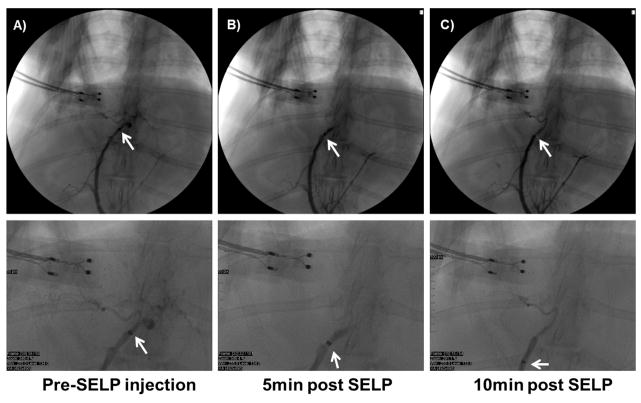
While under general anesthesia, a 2.8 F microcatheter was maneuvered to the proper hepatic artery; however, the right or left hepatic arteries could not be effectively discriminated. A control animal was injected with saline only, equivalent to the volume of the SELP formulation, and the animal was euthanized. The saline control animal served for tissue comparisons post-surgery. SELP-815K was injected into three animals. Pre-injection angiograms showed contrast filling the liver blood vessels confirming full patency of blood flow (Fig. 6A). Each rabbit was injected with 0.8–0.9 mL of sheared 12% w/w SELP-815K in a 1 mL syringe, followed by 0.6mL of saline to flush the polymer from the catheter. Following a 5-minute gelling period, the catheter was pulled back approximately 2–5 millimeters and contrast was injected to assess the level of stasis. Stasis was indicated by the increased pressure required to administer the contrast and visually by the absence of forward flow of contrast (Fig. 6B). While the addition of contrast dye to the SELP-815K formulation aided in visualizing the injected polymer in the major artery at the point of injection, it was not sufficient to visualize the polymer in the smaller vessels nor did it interfere with post-injection angiographic assessment. At 10 minutes post-injection, contrast was re-administered as the catheter was pulled back a few more millimeters. Persistence of the embolus and resistance to contrast injection verified clinically-termed hard stasis (Fig. 6C). The animal was then euthanized and organs were harvested for histological analysis.
Fig. 6. 12% w/w sheared SELP-815K tested in vivo in male New Zealand White rabbits.
A) Contrast observed filling the hepatic arterial supply, with catheter tip in proper hepatic artery. B) Contrast angiography at 5 min post SELP injection shows hard stasis, no flow into hepatic branches. C) Contrast angiography at 10 min post SELP injection shows continued stasis. Below each panel, higher magnification of the image is shown for clarity.
3.6. Histological analysis
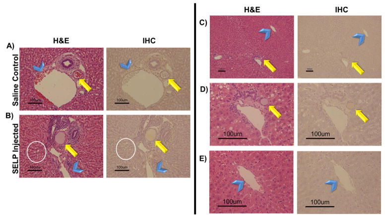
The liver and lungs were immediately harvested for fixation in 10% buffered formalin. Sections from each lobe of the liver were analyzed. Anatomically, the hepatic artery branches down to terminal arterioles that are an element of the portal triad, consisting of a bile duct, arteriole, and venule [29]. These terminal arterioles transition into an arteriosinusoidal branch that continues and becomes the hepatic sinusoids, which empty into the central vein. Lymphatic vessels communicate with these branching vessels of the portal triads as well. In analysis of the liver sections, these anatomical markers were used to identify the path of the injected SELP. The histological images (shown in Fig. 7A–B) provide a direct comparison of the control saline injected animal to a SELP-815K injected animal, focusing on a portal triad, the arterioles (indicated by arrows) and the terminal branches of the portal vein (indicated by arrowheads). The histological sections of the control animals showed arterioles, clearly demarcated by a ring of smooth muscle, filled with red blood cells, indicative of patency. The H&E stained histological sections of SELP-815K-injected animals, showed arterioles filled with an amorphous pink substance. Previous work in our lab has identified SELP-815K histologically by H&E after intratumoral injection as an amorphous pink substance [30]. To confirm its presence, an IHC staining technique using antibodies against SELP-815K identified the polymer signal by correlation with positive control samples of fixed and sectioned SELP-815K gels. In addition to the physical presence of the SELP-815K in the arterioles, a functional attribute of embolization was also evident. Hepatocytes in the histological sections of the SELP injected animals (Fig. 7B, encircled in white) showed a high degree of vacuolization, which is a physiologic response to hypoxia.
Fig. 7. Histological analysis of hepatic tissue locating embolic material.
Rows A) and B) provide histological comparison of control and test animal hepatic tissues showing evidence of SELP filling the hepatic arteriole. Both hematoxylin and eosin (H&E) stain and an immunohistochemistry (IHC) stain specific for SELP were used for visualization. The arrow indicates arterioles and the arrowheads indicate the portal venules, for reference. The presence of vacuolization in the hepatocytes of the test animal (encircled) provides more evidence of hypoxic damage induced by occlusion of the hepatic arterial vessels upstream. Images taken at 152X total magnification. Rows C–E) show evidence of SELP within hepatic arterial supply (indicated by the arrows) and no evidence of flow through into the venous drainage via the hepatic central veins (indicated by the arrowheads). Row C, images taken at 30X total magnification, showing a portal triad and its draining central vein. Rows D and E show the portal triad and central vein individually at 152X total magnification. SELP is evident in row D within the arteriole indicated by the arrow. SELP is not evident tracking to or entering the draining central vein in row E.
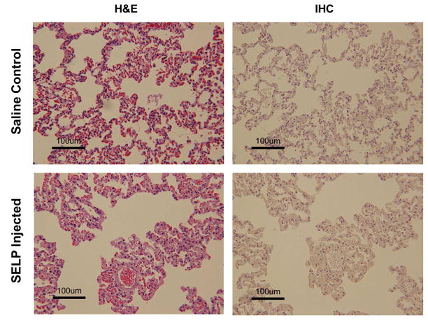
All sections were examined for SELP-815K in draining veins. SELP was visible periodically in hepatic sinusoids, which anastomose with the hepatic arterioles, but there was no evidence of SELP in the draining central veins (indicated by arrowheads in Fig. 7). A series of panels tracking SELP in a portal triad arteriole (arrow) to the draining central vein with increasing magnification are shown in Fig. 7C–E. Row 7D shows the portal triad. Again, SELP is seen filling the entirety of the arteriole. At this magnification, vacuolization is also very apparent in adjacent hepatocytes. Row 7E shows the central vein. No SELP was identified and the amount of red blood cells both within the vein and the venules draining into the vein is less than seen in the control tissues; consistent with upstream blockage. Both lungs were also sectioned and examined for off target embolization (Fig. 8). Multiple sections from each lobe were examined both by H&E and IHC and no evidence of SELP was identified.
Fig. 8. Histological sections of rabbit lungs.
Panels A and B are sections from a saline control animal. Panels C and D are sections from an SELP injected animal. No evidence of SELP in the lungs of test animals was found. Lungs did not show signs of vascular occlusion. Images taken at 76X total magnification.
4. Discussion
Hepatocellular carcinoma has recently emerged as the third leading cause of cancer-related death worldwide [2–9]. The World Health Organization reported 745,000 deaths in 2012. Transarterial chemoembolization, although not curative, has proven to be an effective therapy for intermediate stage disease [9, 10]. However, the materials used in this treatment are highly variable and no global standard exists. The two leading systems include Lipiodol® emulsion with a chemotherapeutic agent that must be followed by particulate embolization with Gelfoam® and drug eluting beads, such as DC Bead®. The attributes of each system were considered and used in the design of a novel embolic using the in situ gelling SELP biomaterial. The goal of this work was to formulate an injectable, aqueous-based material using silk-elastinlike protein polymers capable of transitioning into a physical hydrogel network in vivo without solvent displacement. The system would serve a dual purpose: vessel occlusion and drug delivery. The advantage of the liquid Lipiodol® drug emulsion over the drug eluting beads (DEBs) is its deep permeation into the tumor vasculature, increasing the total diffusive area of the co-administered drug. A liquid SELP formulation would retain this characteristic. The advantage of the solid DEBs is their immediate occlusion of blood vessels upon injection. A SELP that rapidly transitions to a solid hydrogel would achieve this characteristic as well. Therefore, a SELP embolic encompassing the occlusive properties of DEBs and the vasculature permeation of Lipiodol® could provide a single embolizing agent capable of localized release of a variety of therapeutic drugs.
The aim of this work was to produce an injectable SELP formulation that undergoes sol-to-gel transition at body temperature, lodges at the arteriole level and induces hemostasis. Importantly, injectability through commercially available microcatheters commonly used in TACE procedures was required. The maximum injectable viscosity of 150 cP eliminated several candidates. A balance between mechanical properties comprising rapid gelation, robust gel stiffness and injectable viscosity had to be achieved. Because several requirements had to converge, a panel of formulations including two polymers, SELP-47K and SELP-815K, were tested. Formulations of reconstituted lyophilized polymer with no shear processing were initially characterized and while meeting the viscosity specification, they lacked sufficient gelation speed and mechanical stiffness.
Based on previous experience [23], shear processing of the polymer formulations was used to improve the mechanical properties. The effect of shear was clearly shown in both viscosity and gelation. It is hypothesized that the shearing breaks weak intramolecular bonds and allows the polymer strands to align, making stronger long range hydrogen bonds intermolecularly between silk units, which are the chief networking component in SELP hydrogels [23]. While the shearing of high concentration SELP formulations (16% w/w and 14% w/w) resulted in too rapid gelation and excessive viscosity, sheared 12% w/w SELP-47K and SELP-815K both resulted in acceptable viscosity (<150 cP), gelation (<5 minutes), and gel stiffness (>1E5 Pa at 5 hours). The two formulations, however, were distinguished by their gel stiffness at 5 minutes, which if maximized was considered a potential benefit in rapid vascular occlusion. Sheared 12% w/w SELP-815K achieved 10 fold greater gel stiffness at 5 minutes than sheared 12% w/w SELP-47K. The difference was attributed to SELP-815K’s increase in the number of silk and elastin units per polymer repeat (2X) compared to SELP-47K. Thus, sheared 12% w/w SELP-815K was the selected formulation.
Following formulation identification, in vitro studies were conducted to determine if the sheared 12% w/w SELP-815K composition would occlude a microfluidics device representative of a vasculature system under flow conditions. The design of the device provided a simulated environment in which pressure drops occurred with each set of daughter branches to mimic the low pressure environment of hepatic microcirculation. The average blood pressure entering the hepatic artery is 90 mmHg, which quickly drops to <10 mmHg at the arteriosinusiods. By connecting several devices in parallel, representing the hepatic lobules, a low pressure environment was created (<52 mmHg). Injection of sheared 12% SELP-815K under flow conditions successfully and consistently occluded the device.
Occlusion in the in vitro test warranted in vivo investigation. New Zealand white rabbits were chosen in order to enable the use of commercially available microcatheters. While the proper hepatic artery of the rabbit was accessed with the 2.8F microcatheter under fluoroscopic imaging, the right and left hepatic arteries were too small. Therefore, SELP-815K was injected proximally to the branch point of the vessel. Angiography, before and after SELP injection, visibly verified hard stasis in the hepatic vasculature. Flourographic images clearly demarcated the point of stasis (Fig. 6). No forward flow of contrast was identified. Additionally, injection of contrast following SELP embolization required increased injection pressure. This resistance indicated clinically described hard stasis. Furthermore, the second injection of contrast 10 minutes post-embolization showed a stable embolus that did not reorganize or move, a phenomenon observed with gelatin particles used with Lipiodol. Injection of the SELP formulation also required less force than the commercial products and required less material to achieve the same level of stasis. Only 0.8–0.9 mL of SELP was used to embolize the vessels as compared to the 2–4 mL of microspheres (total volume of beads) typically used in a TACE procedure [31]. The SELP formulation did not require multiple injections to achieve occlusion, contrary to microspheres in clinical practice.
Histological analysis of the hepatic tissue complemented the observations during the procedures. SELP-815K was identified within the hepatic arterioles that make up part of the portal triad. SELP was also identified in associated lymphatic vessels, as expected because they intimately interact with the arterioles as well as the sinusoids as they empty into the central veins. The portal venules, also part of the portal triad, anastomose with the hepatic arterioles and provide an avenue for SELP to enter. However, SELP was observed within these venules only in two instances. The portal venules also dump into the sinusoids, which channel blood flow into the central veins, and continue to form the hepatic veins and subsequently the vena cava. There was no evidence of SELP in any of the draining veins indicating that the SELP embolic gelled within the arterial branches with no evident venous washout. Furthermore, the hepatic tissue of the SELP injected animals showed high degrees of vacuolization in the hepatocytes. Hepatocytes are highly metabolically active and small changes in blood supply induce damage evident by vacuolization. Decreased amount of red blood cells throughout the capillaries was another confirmation of upstream occlusion as compared to the saline control samples. Finally, as another assessment of venous washout, the lungs were examined for any off target embolization. No evidence of SELP was present in the lungs of the SELP injected animals. The lung ultrastructure was similar between the saline control and SELP injected animals. Embolization with microspheres has been associated with migration of particles to the lungs [32, 33].
Although these in vivo tests were a feasibility study, the results provide clear indication that the sheared 12% w/w SELP-815K formulation formed a solid gel network within the catheterized arteries of the liver and remained lodged in the hepatic tissue. No off target embolization indicates that the SELP formulation entered the microcirculation of the liver and gelled before venous washout, satisfying the final specification and validation of our hypothesis. Further investigation of in vivo performance and safety of SELP-815K over longer periods of time to determine intravascular stability, both in tumor and non-tumor bearing animals is warranted. Moreover, a drug delivery component must be added to develop a therapeutically effective chemoembolic to treat hepatocellular carcinoma.
5. Conclusion
Based on specified design parameters, sheared 12% w/w SELP-815K formulation was developed as an injectable embolic candidate. In vivo evaluation provided further evidence that this material occluded the targeted hepatic arterial blood supply in the rabbit liver. Histological examination of the injected tissue showed SELP occluding at the arterial level without drainage into the venous system via the central veins to systemic circulation. This data suggests that SELP-815K may be used as an in situ gelling liquid embolic in TACE and warrants further investigation to determine long term residence and therapeutic efficacy in hepatic tumors. The next phase of this work requires investigation of drug loading levels of the gel followed by chemotherapeutic effects.
Supplementary Material
The entry channel is 1000 μm in width and each branch divides into two daughter branches until reaching 50 μm, representing small arterioles, then increasing in size back to 1000 μm. The height of the channels is 100 μm throughout the device. Soft lithography techniques were used to fabricate the device mold, and the devices were constructed of polydimethylsiloxane.
Acknowledgments
The authors would like to thank the University of Utah’s Comparative Medicine for use of facility and equipment for all surgical procedures along with Misti Seppi for surgical prep work; Sheryl Tripp of ARUP for developing an immunohistochemistry staining protocol staining for SELP in tissue samples; and Josh Conarton for modeling a 3D SolidWorks image of the microfluidics device. Financial support for this work was provided by NIH grants R41 CA168123, RO1 CA107621, and F30 CA176922, and a fellowship from the Nanotechnology Training Program, University of Utah.
Footnotes
Publisher's Disclaimer: This is a PDF file of an unedited manuscript that has been accepted for publication. As a service to our customers we are providing this early version of the manuscript. The manuscript will undergo copyediting, typesetting, and review of the resulting proof before it is published in its final citable form. Please note that during the production process errors may be discovered which could affect the content, and all legal disclaimers that apply to the journal pertain.
References
- 1.Center MM, Jemal A. International Trends in Liver Cancer Incidence Rates. Cancer Epidemiology Biomarkers & Prevention. 2011;20:2362–8. doi: 10.1158/1055-9965.EPI-11-0643. [DOI] [PubMed] [Google Scholar]
- 2.El-Serag HB. Hepatocellular Carcinoma. New England Journal of Medicine. 2011;365:1118–27. doi: 10.1056/NEJMra1001683. [DOI] [PubMed] [Google Scholar]
- 3.Montella L, Addeo R, Caraglia M, Del Prete S. Latest Developments in Targeted Therapy for Hepatocellular Carcinoma. Expert Review of Anticancer Therapy. 2010;10:1635–46. doi: 10.1586/era.10.146. [DOI] [PubMed] [Google Scholar]
- 4.Brown DB, Nikolic B, Covey AM, Nutting CW, Saad WE, Salem R, et al. Quality Improvement Guidelines for Transhepatic Arterial Chemoembolization, Embolization, and Chemotherapeutic Infusion for Hepatic Malignancy. Journal of Vascular and Interventional Radiology. 2012;23:287–94. doi: 10.1016/j.jvir.2011.11.029. [DOI] [PubMed] [Google Scholar]
- 5.Forner A, Llovet JM, Bruix J. Hepatocellular Carcinoma. Lancet. 2012;379:1245–55. doi: 10.1016/S0140-6736(11)61347-0. [DOI] [PubMed] [Google Scholar]
- 6.SEER Cancer Statistics Review, 1975–2009 (Vintage 2009 Populations) National Cancer Institute; Bethesda, MD: 2011. Available from URL http://seer.cancer.gov/csr/1975_2009_pops09/ [Google Scholar]
- 7.Bruix J, Sherman M. Management of Hepatocellular Carcinoma. Hepatology. 2005;42:1208–36. doi: 10.1002/hep.20933. [DOI] [PubMed] [Google Scholar]
- 8.Hernandez-Gea V, Toffanin S, Friedman SL, Llovet JM. Role of the Microenvironment in the Pathogenesis and Treatment of Hepatocellular Carcinoma. Gastroenterology. 2013;144:512–27. doi: 10.1053/j.gastro.2013.01.002. [DOI] [PMC free article] [PubMed] [Google Scholar]
- 9.Llovet JM, Bruix J. Systematic Review of Rrandomized Trials for Unresectable Hepatocellular Carcinoma: Chemoembolization Improves Survival. Hepatology. 2003;37:429–42. doi: 10.1053/jhep.2003.50047. [DOI] [PubMed] [Google Scholar]
- 10.Dufour JF, Bargellini I, De Maria N, De Simone P, Goulis I, Marinho RT. Intermediate Hepatocellular Carcinoma: Current Treatments and Future Perspectives. Annals of Oncology. 2013;24:24–9. doi: 10.1093/annonc/mdt054. [DOI] [PubMed] [Google Scholar]
- 11.Altekruse SF, McGlynn KA, Reichman ME. Hepatocellular Carcinoma Incidence, Mortality, and Survival Trends in the United States from 1975 to 2005. Journal of Clinical Oncology. 2009;27:1485–91. doi: 10.1200/JCO.2008.20.7753. [DOI] [PMC free article] [PubMed] [Google Scholar]
- 12.Lewis AL, Dreher MR. Locoregional Drug Delivery Using Image-Guided Intra-Arterial Drug Eluting Bead Therapy. Journal of Controlled Release. 2012;161:338–50. doi: 10.1016/j.jconrel.2012.01.018. [DOI] [PMC free article] [PubMed] [Google Scholar]
- 13.Tam KY, Leung KC, Wang YX. Chemoembolization Agents for Cancer Treatment. European Journal of Pharmaceutical Sciences. 2011;44:1–10. doi: 10.1016/j.ejps.2011.06.013. [DOI] [PubMed] [Google Scholar]
- 14.Barkey NM, Tafreshi NK, Josan JS, De Silva CR, Sill KN, Hruby VJ, et al. Development of Melanoma-Targeted Polymer Micelles by Conjugation of a Melanocortin 1 Receptor (MC1R) Specific Ligand. Journal of Medicinal Chemistry. 2011;54:8078–84. doi: 10.1021/jm201226w. [DOI] [PMC free article] [PubMed] [Google Scholar]
- 15.Bruix J, Sherman M. Management of Hepatocellular Carcinoma: an Update. Hepatology. 2011;53:1020–2. doi: 10.1002/hep.24199. [DOI] [PMC free article] [PubMed] [Google Scholar]
- 16.Bruix J, Llovet JM. Two Decades of Advances in Hepatocellular Carcinoma Research. Seminars in Liver Disease. 2010;30:1–2. doi: 10.1055/s-0030-1247219. [DOI] [PubMed] [Google Scholar]
- 17.Laurent A. Microspheres and Nonspherical Particles for Embolization. Techniques in Vascular and Interventional Radiology. 2007;10:248–56. doi: 10.1053/j.tvir.2008.03.010. [DOI] [PubMed] [Google Scholar]
- 18.Cappello J, Crissman J, Dorman M, Mikolajczak M, Textor G, Marquet M, et al. Genetic Engineering of Structural Protein Polymers. Biotechnology Progress. 1990;6:198–202. doi: 10.1021/bp00003a006. [DOI] [PubMed] [Google Scholar]
- 19.Cappello J, Crissman JW, Crissman M, Ferrari FA, Textor G, Wallis O, et al. In-Situ Self-Assembling Protein Polymer Gel Systems for Administration, Delivery, and Release of Drugs. Journal of Controlled Release. 1998;53:105–17. doi: 10.1016/s0168-3659(97)00243-5. [DOI] [PubMed] [Google Scholar]
- 20.Cappello J, Ghandehari H. Engineered Protein Polymers for Drug Delivery and Biomedical Applications. Advanced Drug Delivery Reviews. 2002;54:1053–5. doi: 10.1016/s0169-409x(02)00063-7. [DOI] [PubMed] [Google Scholar]
- 21.Ghandehari H. Recombinant Biomaterials for Pharmaceutical and Biomedical Applications. Pharmaceutical Research. 2008;25:672–3. doi: 10.1007/s11095-007-9419-9. [DOI] [PubMed] [Google Scholar]
- 22.Dandu R, Cresce AV, Briber R, Dowell P, Cappello J, Ghandehari H. Silk–Elastinlike Protein Polymer Hydrogels: Influence of Monomer Sequence on Physicochemical Properties. Polymer. 2009;50:366–74. [Google Scholar]
- 23.Price R, Poursaid A, Cappello J, Ghandehari H. Effect of Shear on Physicochemical Properties of Matrix Metalloproteinase Responsive Silk-Elastinlike Hydrogels. Journal of Controlled Release. 2014;195:92–8. doi: 10.1016/j.jconrel.2014.07.044. [DOI] [PMC free article] [PubMed] [Google Scholar]
- 24.Barber RW, Emerson DR. Biomimetic Design of Artificial Micro-Vasculatures for Tissue Engineering. Alternatives to Laboratory Animals. 2010;38 (Suppl 1):67–79. doi: 10.1177/026119291003801S02. [DOI] [PubMed] [Google Scholar]
- 25.Emerson DR, Cieslicki K, Gu X, Barber RW. Biomimetic Design of Microfluidic Manifolds Based on a Generalised Murray’s Law. Lab on a Chip. 2006;6:447–54. doi: 10.1039/b516975e. [DOI] [PubMed] [Google Scholar]
- 26.Murray CD. The Physiological Principle of Minimum Work. I. The Vascular System and the Cost of Blood Volume. Proceedings of the National Academy of Sciences; 1926; pp. 207–14. [DOI] [PMC free article] [PubMed] [Google Scholar]
- 27.Rhoades RA, Bell DR. Medical Physiology: Principles for Clinical Medicine. Lippincott Williams & Wilkins; 2012. [Google Scholar]
- 28.Gaehtgens P, Meiselman HJ, Wayland H. Erythrocyte Flow Velocities in Mesenteric Microvessels of the Cat. Microvascular Research. 1970;2:151–62. doi: 10.1016/0026-2862(70)90003-8. [DOI] [PubMed] [Google Scholar]
- 29.Blumgart LH. Surgery of the Liver, Biliary Tract, and Pancreas. Vol. 1. Philadelphia, PA: Saunders, Elsevier; 2007. [Google Scholar]
- 30.Price R, Gustafson J, Greish K, Cappello J, McGill L, Ghandehari H. Comparison of Silk-Elastinlike Protein Polymer Hydrogel and Poloxamer in Matrix-Mediated Gene Delivery. International Journal of Pharmaceutics. 2012;427:97–104. doi: 10.1016/j.ijpharm.2011.09.037. [DOI] [PMC free article] [PubMed] [Google Scholar]
- 31.Lencioni R, de Baere T, Burrel M, Caridi JG, Lammer J, Malagari K, et al. Transcatheter Treatment of Hepatocellular Carcinoma with Doxorubicin-Loaded DC Bead (DEBDOX): Technical Recommendations. Cardiovascular and Interventional Radiology. 2012;35:980–5. doi: 10.1007/s00270-011-0287-7. [DOI] [PMC free article] [PubMed] [Google Scholar]
- 32.Clark TW. Seminars in Interventional Radiology. Thieme Medical Publishers; 2006. Complications of Hepatic Chemoembolization; p. 119. [DOI] [PMC free article] [PubMed] [Google Scholar]
- 33.Brown KT. Fatal Pulmonary Complications after Arterial Embolization with 40–120-μm Tris-acryl Gelatin Microspheres. Journal of Vascular and Interventional Radiology. 15:197–200. doi: 10.1097/01.rvi.0000109400.52762.1f. [DOI] [PubMed] [Google Scholar]
Associated Data
This section collects any data citations, data availability statements, or supplementary materials included in this article.
Supplementary Materials
The entry channel is 1000 μm in width and each branch divides into two daughter branches until reaching 50 μm, representing small arterioles, then increasing in size back to 1000 μm. The height of the channels is 100 μm throughout the device. Soft lithography techniques were used to fabricate the device mold, and the devices were constructed of polydimethylsiloxane.


