Abstract
A novel light source - light blanket composed of a series of parallel cylindrical diffusing fibers (CDF) is designed to substitute the hand-held point source in the PDT treatment of the malignant pleural or intraperitoneal diseases. It achieves more uniform light delivery and less operation time in operating room. The preliminary experiment was performed for a 9cmx9cm light blanket composed of 8 9-cm CDFs. The linear diffusers were placed in parallel finger-like pockets. The blanket is filled with 0.2 % intralipid scattering medium to improve the uniformity of light distribution. 0.3-mm aluminum foil is used to shield and reflect the light transmission. The full width of the profile of light distribution at half maximum along the perpendicular direction is 7.9cm and 8.1cm with no intralipid and with intralipid. The peak value of the light fluence rate profiles per input power is 11.7mW/cm2/W and 8.6mW/cm2/W respectively. The distribution of light field is scanned using the isotropic detector and the motorized platform. The average fluence rate per input power is 8.6 mW/cm2/W and the standard deviation is 1.6 mW/cm2/W for the scan in air, 7.4 mW/cm2/W and 1.1 mW/cm2/W for the scan with the intralipid layer. The average fluence rate per input power and the standard deviation are 20.0 mW/cm2/W and 2.6 mW/cm2/W respectively in the tissue mimic phantom test. The light blanket design produces a reasonably uniform field for effective light coverage and is flexible to confirm to anatomic structures in intraoperative PDT. It also has great potential value for superficial PDT treatment in clinical application.
Keywords: Photodynamic therapy, intraperitoneal PDT, pleural PDT, light source, light blanket
I. INTRODUCTION
Photodynamic therapy (PDT) is used in a number of medical fields including oncology (cancer), dermatology (skin), and cosmetic surgery in nowadays. In oncology, it is FDA approved for non-small cell lung cancer, esophageal cancer, and precancerous changes of Barrett's esophagus. Its use is also being further investigated through clinical trials in general oncology for conditions including cancers of the cervix (mouth of uterus), prostate gland, brain, and peritoneal cavity (the abdominal space that contains the stomach, liver, and internal organs). The prostate gland is also an organ that appears to be a good target for interstitial PDT.
In our pleural and intraperitoneal (IP) PDT clinical trials, a point source constructed from a modified endotracheal tube filled with intralipid scattering liquid is used to delivery light to the tissue cavities (abdominal or chest cavities). The diffusing optical probe consisting of an optical fiber mounted in a modified endotracheal tube that terminated in a balloon filled with 0.1% introlipid solution (Fig. 1b). The point source goes surrounding the cavity to cover the whole treatment area (Fig. 1a). The current method of light delivery is highly dependent on the pattern of light source movement by the surgeon.
Figure 1.
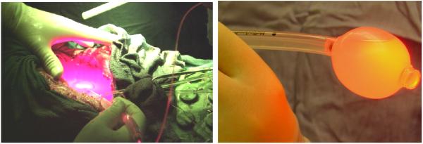
(a) Red light delivery for pleural PDT (b) Hand-held point source
In-vivo light dosimetry for patients undergoing intraoperative PDT is one of the critical dosimetry quantities for predicting results of the treatment. Seven photodiode detectors were sewn to the wall of the pleural cavity for monitoring the light dose in the following sites inside of the abdominal or chest volume (Fig. 2): Apex, anterior medial chest wall (ACW), posterior chest wall (PCW), posterior diaphragmatic sulcus (PS), anterior diaphragmatic sulcus (AS), posterior mediastinum (PM) and pericardium (Peri). The illumination was delivered under manual control until the prescribed dose of was reached at all sites. The light uniformity depends on the positions of the photodiodes and experiences of the surgeon.
Figure 2.
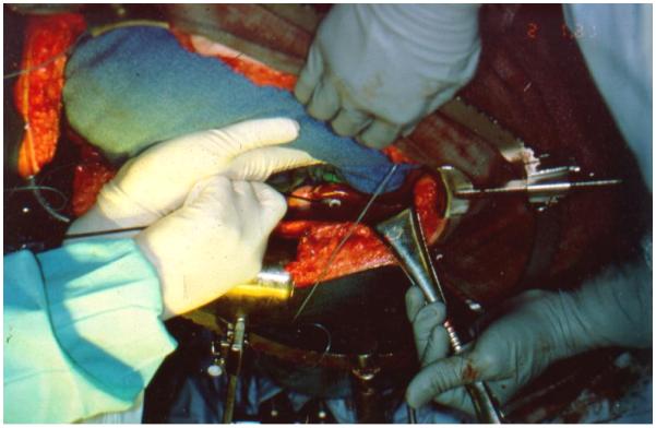
In vivo dosimetry with photodiodes
To improve the uniformity of light delivery for the pleural and IP PDT, a light blanket was designed, and a prototype is fabricated. It is flexible and easy to conform to the curved interior surfaces of these surgical cavities, and will have potential value for the clinical application when the treatment area is not easily accessible by collimated light sources.
Current attempts in developing flexible light blanket for medical application incorporate textile plastic optical fibers for topical light delivery. The flexible light sources could be wrapped around target sites and is commonly designed for low power use for external skin. Selm et al. [1, 2] had reported to use a textile light diffuser for PDT, which was applied to homogeneously illuminate unequal body surfaces. Rothmaier performed the pulse oximetry with the photonic textile by using near infrared spectroscopy[3]. These light blankets, however, is currently not suitable for use in IP and PDT for the following reasons: (1) The light blanket has to be capable of delivery relatively high light power (4 – 7 W) without causing thermal heating, The textile blanket reported had 40% transmission efficiency and will raise the skin temperature to 43°C after 10 minutes delivery at 1W input power. (2) The light blanket has to be water-tight since the abdominal cavity is filled with saline during PDT and surgery procedure. (3) The light blanket should maintain uniformity of light distribution for the treatment area under pressure. This is one area of the weakness of the current generation of the textile light blanket since the output changes with applied external pressure on the blanket.
In order to remedy the issues above, a light blanket composed of individual cylindrical diffuser fibers (CDF) is designed. The mechanism of our light blanket is different from that used in a luminous textile structure. The basic idea is using multiple CDFs and surrounding them with scattering medium (e.g., intralipid solution) will produce uniformly distributed diffused light over a large area. The advantages are: (1) Thermal effect under high input laser power is reduced since there is negligible thermal loss at the output end of CDFs. (2) The light blanket is water tight with thermal sealing polymer and composite materials and output is independent of pressure. (3) Since the light distribution profile of each individual CDF can be quantified individually, we can use the computerized attenuator to control the power of each channel for the optimization of the light uniformity.
II. METHODS AND MATERIALS
1. Blanket design and Fabrication
The light blanket composed of a series of parallel cylindrical diffusing fibers (CDF) is designed (Figure 3(a)). The CDFs are sealed with polymer and composite materials by thermal sealing. A prototype blanket was made using polyethylene (Figure 3(b)). Eight 9cm long linear diffusers were placed in parallel finger-like pockets. The spacing distance between adjacent fibers is 1 cm. The fiber pockets were immersed in intralipid solution in the blanket. The active area of the blanket was ~9×9 cm2, which can be enlarged if longer fibers are used. The blanket is filled with 0.2% intralipid scattering medium to improve the uniformity of light distribution. On one side of the blanket, 0.3mm aluminum foil was used to construct the reflection layer for the light transmission to enhance the efficiency of light delivery.
Figure 3.

(a) Schematics of light blanket design and (b) a picture of the prototype of light blanket
The blanket is water-proofed, and the polyethylene cover is specialized for clinic. It is feasible for the sterilization in Operation Room (OR). The linear cylindrical fibers and flexible polymer materials provide the capability for the conformation with anatomic structures.
2. Experimental setup to characterize light fluence rate distribution
The light distribution was measured by an isotropic detectors on the entire 2D plane of the light blanket in air and on the entire 2D plan with intralipid solution layer of certain concentration. The experimental setup is shown in Figure 4 (a).
Figure 4.
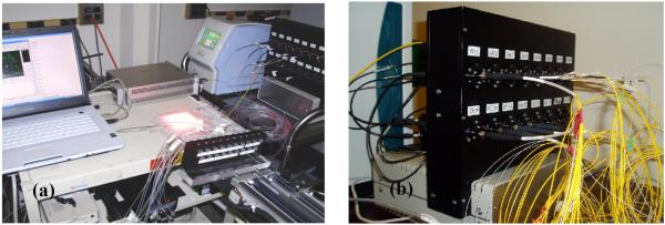
(a) Experimental setup for characterize the light fluence rate and (b) Beamsplitter and attenuation system for light source control.
The maximum output level of 690nm laser machine is 8W. The laser is was split into 12 channels by the beamsplitter. Each channel is connected to corresponding attenuator in the 16-channel computerized attenuation system Figure 4 (b). All the attenuators are kept fully open in our preliminary experiments currently. The light fluence distribution can be modulated potentially by adjusting the power distribution to individual CDFs on the light blanket in the future.
The isotropic detector is placed in the catheter for the scan in air and the scan with intralipid solution layer (see in Figure 5(a) and 5(b)). The scan was performed across the active area line by line perpendicular to the CDFs, with the separation of 1 cm. The motorize platform pulls the detector along the catheter with the speed up to 12mm/s. There was the 0.05mm spacing between two sampling points, The whole travel range was 140mm. The detector is connected to the dosimetry system, which has the sampling rate of 1000/s. The laptop is used for the control of the motor and sampling the data from the dosimetry system.
Figure 5.
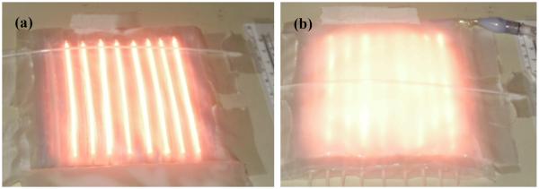
Experimental setup for light fluence rate scan of the light blanket in air (a) without and (b) with an additional intralipid layer
3. Experimental setup for tissue simulating phantom test
The blanket is attached to the1.2% TiO2 tissue mimic phantom. Active area is scanned by the isotropic detector to determine the light distribution close to the surface of normal tissue, with full backscatter of light, the diameter of tissue mimic phantom is 10cm. The thickness of the phantom is 6 cm. The optical properties are , μa = 0.03/cm. With the limit of the phantom dimension, 6 cylindrical diffusers were put inside of the blanket. The spacing distance between the adjacent diffusers is 1cm.
III. RESULTS AND DISCUSSIONS
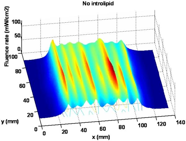
Figure 7 shows the 3D light distribution of the scan in air without intralipid layer. The average fluence rate and standard deviation are calculated using equation (1) and (2), based on the statistics of the data acquired from the dosimetry system. The average of fluence rate per input power () is 8.6 mW/cm2/W, and the standard deviation (Dev) of fluence rate is 1.6 mW/cm2/W.
| (1) |
| (2) |
where ϕi is the light fluence rate measured at location i and Winput is the total input light power.
Figure 7.
Light distribution for the scan without intralipid
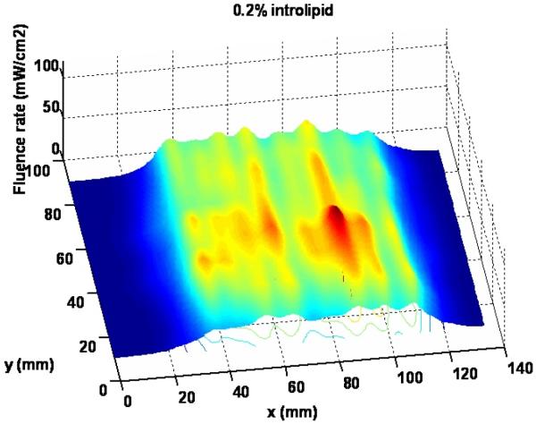
Figure 8 shows the 3D light distribution of the scan in air with 0.2% intralipid solution layer. The average fluence rate per input power and standard deviation are calculated using equations (1) and (2) as 7.4 mW/cm2/W and 1.1 mW/cm2/W, respectively, based on the statistics of the data acquired from the dosimetry system. Apparently, intralipid layer is improving the uniformity of light fluence distribution of the blanket. The intralipid concentration needs to be optimized for uniformity light distribution and output power level. The improvement of the light uniformity with introlipid will be also shown in the profiles of light delivered by blanket.
Figure 8.
Light distribution for the scan with 0.2% intralipid solution layer
The profiles of fluence rate delivered by the blanket are obtained on a certain scanning slice. Figure 9 shows the comparison of light profiles without intralipid and with 0.2% intrepid. The full width at half maximum along the perpendicular direction is 7.9cm or 8.1 cm with no intralipid or with 0.2% intralipid, respectively. The peak value of the light fluence rate profile per input power is 11.7mW/cm2/W and 8.6mW/cm2/W, respectively. The intralipid improves the light distribution, at the same time it will attenuate the output power of light delivered to some extent. 0.2% is a reasonable intralipid concentration to compromise the output power level and light uniformity for the blanket design.
Figure 9.
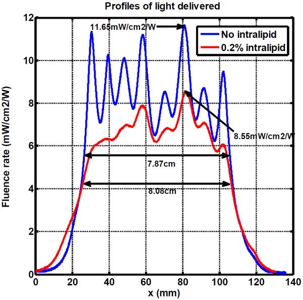
Profiles of light delivered with no intralipid and 0.2% intralipid
The main part of energy loss comes from the transmission through the beam splitter. The previous generation of our beamsplitter only had the 25% transmission efficiency. The transmission efficiency of current beamsplitter is 61.7%. The light transmission efficiency of the entire light blanket system can be calculated using the average fluence rate that was obtained from the in air scan and the area of the light blanket. The transmission efficiency (η) of current beamsplitter is defined as the ratio of total light power output and total input light power (Winput) and is calculated by:
| (3) |
where A is area of the blanket, a is length and b is width of the blanket, and is the light fluence rate.
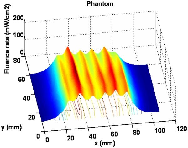
Figure 10 shows the 3D light distribution of the scan with the tissue mimic phantom. The average fluence rate per input power and standard deviation are 20.0 mW/cm2/W and 2.6 mW/cm2/W respectively, based on the statistics of the data acquired from the dosimetry system.
Figure 10.
Light distribution for the scan with tissue mimic phantom
Typical treatment time for pleural PDT is 1 hour (3600 second) and the treatment time for IP PDT is 1.5 to 2.5 hours depending on the area of the cavity. The total target light fluence is typically 60 J/cm2 for pleural PDT and 18 J/cm2 for IP PDT; both using photofrin injected 24 hours before surgery at light wavelength of 630 nm. Thus the average incident light fluence rate is 8.3 mW/cm2 (60J/cm2*1000mW/W /3600s/2) for pleural and ~ 4.1 mW/cm2 (8.3/2) for IP PDT, respectively. This calculation is based on the average measured light fluence enhancement factor of 2 for pleural PDT[4] and 1.8 for IP PDT[5] due to tissue backscattering.
The fluence rate generated by the blanket can meet requirements for the light delivery in pleural or intraperitoneal PDT with 1W input power. Equivalent light fluence rate for a larger treatment area (8 to 15 times than the 10×10cm2) can be achieved using a higher output laser (typically 8 – 15 W). The light distribution is more uniform compared with the hand-held point source currently used in clinic, under the same condition of full light backscatter.
IV. CONCLUSION
A blanket composed of a series of parallel cylindrical diffusing fibers (CDF) is designed to substitute the hand-held point source in the photodynamic therapy treatment of the malignant pleural or intraperitoneal diseases. The light blanket produces a reasonably uniform field for effective coverage and is flexible to confirm to anatomic structures.
To improve the uniformity of light fluence distribution of the blanket, the intralipid concentrations was adjusted to find the optimal concentration for both uniformity and output level. 0.2% is reasonable intralipid concentration to compromised the output power level and light uniformity for the current blanket design. With more efficient beamsplitter (>50%), the light distribution and phantom scanning shows that the light blanket can produce the reasonably uniform field for effective coverage and is flexible to confirm to anatomic structures. The blanket has great potential value for any clinical superficial PDT treatment compared with collimated light sources.
All the preliminary experimental study above was carried out without the adjustment of the attenuation system. The uniform light distribution depends on beam splitter transmission, blanket fabrication and the transmission of linear cylindrical diffuser itself. It is quite necessary to use the 16 channel attenuation system to modulate the light delivery of the blanket. Using a computerized attenuator, we can control the power of individual channel to optimize the uniformity of the light blanket. Automatic feedback schemes can be developed using imbedded isotropic detectors to achieve uniform light fluence distribution for any tissue surface by computer control of power to CDFs.
In the future, computerized modulation of light fluence distribution will be performed by adjusting the power distribution to individual CDFs on the light blanket. A larger area more blanket will be designed and fabricated with 26-cm long CDF to produce a 20 × 26 cm2 light blanket composed of 16 26-cm CDFs with 1.25 cm spacing. The actual mean spacing between the CDFs will be adjusted to find the optimal distances for the uniform light fluence distribution.
Figure 6.
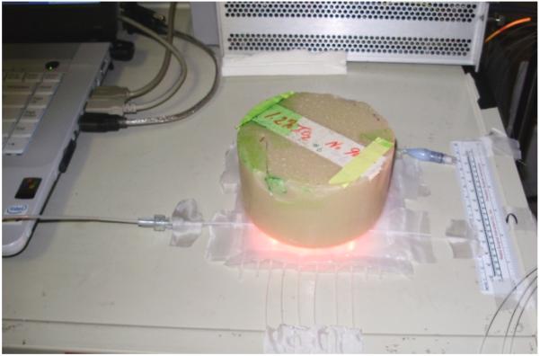
Experimental setup for tissue mimic phantom
ACKNOWLEDGMENT
The authors would like to thank Dr. Jun Li and Dr. Jarod C Finlay for their help in making the prototype device and for setting up measurement instruments. This work is supported by grants from National Institute of Health (NIH) P01 CA87971.
VI. REFERENCES
- [1].Selm B, Rothmarier M, Camerzind M, Khan T, Walt H. “Novel flexible light diffuser and irradiation properties for photodynamic therapy. ” J Biomed Opt. 2007;12(3):034024. doi: 10.1117/1.2749737. [DOI] [PubMed] [Google Scholar]
- [2].Selm B.a.M.C. “Flexible textile light diffuser for photodynamic therapy. ” Proc. SPIE. 2005;5691:95–103. [Google Scholar]
- [3].Rothmaier M, Selm B, Spichtig S, Haensse D, Wolf M. “Photonic textiles for pulse oximetry. ” Opt. Exp. 2008;16(17):12973–12986. doi: 10.1364/oe.16.012973. [DOI] [PubMed] [Google Scholar]
- [4].Zhu TC, Dimofte A, Friedberg JS, Miles J, Glatstein E, Hahn SM. “The Ratio of the Spherical and Flat Detectors at Tissue Surfaces During Pleural Photodynamic Therapy. ” Proc. SPIE. 2002;4592:56–67. doi: 10.1117/12.469337. [DOI] [PMC free article] [PubMed] [Google Scholar]
- [5].Vulcan TG, Zhu TC, Rodriguez CE, Hsi A, Fraker DL, Baas P, Murrer LH, Star WM, Glatstein E, Yodh AG, Hahn SM. “Comparison between isotropic and nonisotropic dosimetry systems during intraperitoneal photodynamic therapy. ” Lasers Surg Med. 2000;26(3):292–301. doi: 10.1002/(sici)1096-9101(2000)26:3<292::aid-lsm7>3.0.co;2-t. [DOI] [PubMed] [Google Scholar]


