Abstract
Purpose
Validation of a novel minimally-invasive, image-guided approach to implant electrodes from three FDA-approved manufacturers—Medel, Cochlear, and Advanced Bionics—in the cochlea via a linear tunnel from the lateral cranium through the facial recess to the cochlea.
Methods
Custom microstereotactic frames that mount on bone-implanted fiducial markers and constrain the drill along the desired path were utilized on seven cadaver specimens. A linear tunnel was drilled from the lateral skull to the cochlea followed by a marginal, round-window cochleostomy and insertion of the electrode array into the cochlea through the drilled tunnel. Post-insertion CT scan and histological analysis were used to analyze the results.
Results
All specimens (N=7) were successfully implanted without visible injury to the facial nerve. The Medel electrodes (N=3) had minimal intracochlear trauma with 8, 8, and 10 (out of 12) electrodes intracochlear. The Cochlear lateral wall electrodes (straight research arrays) (N=2) had minimal trauma with 20 and 21 of 22 electrodes intracochlear. The Advanced Bionics electrodes (N=2) were inserted using their insertion tool; one had minimal insertion trauma and 14 of 16 electrodes intracochlear while the other had violation of the basilar membrane just deep to the cochleostomy following which it remained in scala vestibuli with 13 of 16 electrodes intracochlear.
Conclusions
Minimally invasive, image-guided cochlear implantation is possible using electrodes from the three FDA-approved manufacturers. Lateral wall electrodes were associated with less intracochlear trauma suggesting that they may be better suited for this surgical technique.
Keywords: cochlear implant, minimally invasive surgery, image-guided surgery, microstereotactic frame, electrode placement
Introduction
Since its approval from Food and Drug Administration (FDA) in 1985, cochlear implants (CI) have become the standard of care for patients with bilateral profound sensorineural hearing loss. To date, well over 200,000 CIs have been performed [1]. While most CIs are done through the traditional technique of mastoidectomy and posterior tympanotomy, variations have been proposed that minimize invasiveness such as the endaural approach [2], the suprameatal approach (SMA) [3,4], and minimal access incision techniques [5–7]. Some techniques are more amenable to use of certain electrode designs. For example, the SMA approach involves guiding an electrode from the attic to the middle ear and then turning it approximately 90 degrees to enter the cochlea and hence is typically done with a flexible lateral wall electrode.
One of the proposed variations in surgical technique capitalizes on the use of image-guidance to accurately guide a drill from the lateral mastoid surface, through the facial recess, and into the cochlea. Previously referred to as percutaneous cochlear implantation (PCI), the technique has been validated in vitro [8–10] and in vivo [11,12] documenting safe passage of sham drill bits through the facial recess without injury to the facial nerve. This technique has undergone refinement since initial reports [11,13] including intraoperative CT scanning to allow placement of bone-implanted fiducial markers at the time of surgery [14], development of a rapidly-created (< 10 minute manufacturing time) customized microstereotactic frame which mounts on the bone-implanted fiducial markers and guides drill bits along the desired trajectory [9,12], and development of a drill press to accurately drill from the lateral cortex to the cochlea using the microstereotactic frame [10].
In preparation for clinical implementation of image-guided, minimally-invasive cochlear implantation, we undertook a cadaveric study of complete implementation of the technique using electrode arrays from the three FDA-approved cochlear implant manufacturers. We report herein the feasibility of this technique in a cadaver model as well as outcomes regarding placement of the electrode array.
Method
Seven cadaveric temporal bones were used in this study. These bones were harvested according to our institution’s anatomical gifts program which involved post-mortem fixation and, once harvested, were stored in a freezer. Being de-identified, no information about their prior health status was available. As post-mortem specimens are considered non-human research, institutional review board approval was not required. Mirroring clinical implementation of the technique, surgical steps performed on the temporal bones were as follows. Note that for clinical implementation, Steps 1 and 2 below would be performed prior to the beginning of the surgery with all other steps performed in the operating room.
Step 1: Acquisition of Preoperative CT Scan
A clinically-applicable temporal bone CT scan was obtained. At our institution, we use a 16-slice Philips Mx8000 IDT 16 CT scanner that can provide a voxel resolution of 0.25-by-0.25-by-0.4 mm.
Step 2: Preoperative Trajectory Planning
Using the methods described by Noble et al. [15,16] the significant structures of the ear surrounding the cochlea—namely, the facial nerve, the chorda tympani, the cochlea, the labyrinth, the ossicles, and the external auditory canal—were automatically segmented in the preoperative CT. A safe drill trajectory was then automatically determined that avoids damage to the facial nerve and targets scala tympani within the cochlea (Figure 1) [17]. This step is performed in approximately three minutes with an Intel Xeon 2.4 GHz dual quad-core 64-bit machine with 10 GB random access memory. The segmentation results and safe trajectory, as determined by the software, were confirmed by the surgeon before proceeding to the next step. Note that while planning for a patient, if the software specifies that a safe trajectory cannot be determined or the surgeon is not satisfied with the results of the automatic trajectory planning, the process would be terminated and a traditional approach used.
Figure 1.
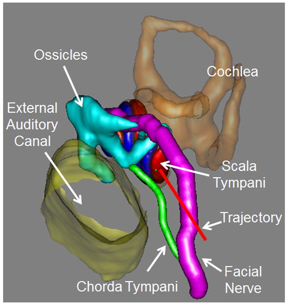
Automatic trajectory planning using the preoperative CT
Step 3: Implantation of Bone-Implanted Fiducial Markers
Three fiducial markers were bone-implanted on the lateral skull behind the ear surrounding the cochlea at the mastoid tip, in the suprahelical region, and in the region posterior to the sigmoid sinus (Figure 2). Titanium anchors were screwed into the bone and a spherical extender fastened onto the anchor. The spherical tip functions as both a fiducial marker as well as an attachment point for the customized microstereotactic frame via a ball and socket assembly.
Figure 2.
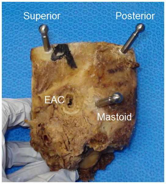
Bone-implanted markers surrounding the cochlea with spherical extenders. (EAC=external auditory canal)
Step 4: Acquisition of Intraoperative CT Scan
Intraoperative CT scanning was performed using a portable CT scanner ensuring that all the fiducial markers were inside the field of view. At our institution, we use an xCAT ENT mobile CT scanner (Xoran Technologies, Ann Arbor, MI) to acquire scans with voxel size of 0.3 × 0.3 × 0.3 mm.
Step 5: Transformation of Planned trajectory to Intraoperative CT
The centers of the spherical markers are automatically determined via fitting a spherical model of the marker to the CT scan [18]. A standard mutual information method [19] for performing rigid registration was used to align the preoperative and intraoperative CT scans of the specimens. As such, the safe trajectory from Step 2 is now identifiable in the intraoperative CT scan which contains the bone-implanted fiducial markers. Output from this step is the x, y, and z coordinates of the spherical markers as well as the x, y, and z coordinates of two points along the trajectory (i.e. target and entry). This step takes approximately four minutes.
Step 6: Design and Fabrication of Customized Microstereotactic Frame
Using the locations of the five points specified by Step 5, a customized microstereotactic frame, which mounts on the three fiducial markers and achieves the desired trajectory, is designed using a custom software program written in Matlab (The Mathworks, Natick, MA) [9]. The program generates a virtual model of the microstereotactic frame and an instruction file composed of G-code commands, which is used to control a computer-numeric-control (CNC) milling machine in constructing the frame. The top of the frame was then fabricated on a standard CNC milling machine (Ameritech CNC, Broussard Enterprises, Inc., Santa Fe Springs, CA) from an Ultem slab (Quadrant Engineering Plastic Products, Reading, PA). Next, legs of desired lengths as determined by the program are inserted into the three leg holes of the top of the frame and tightened into place. An adaptor is then attached to the targeting hole (Figure 3) that mates with a custom-designed drill-press [10]. Total time for Step 6 is typically under 10 minutes.
Figure 3.
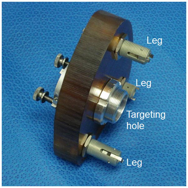
Customized microstereotactic frame. The microstereotactic frame is mounted on the patient (cadaver specimen in our case) by attaching the legs to the corresponding spherical fiducial markers. When a drill press is attached to the targeting hole, the frame precisely guides the drill along the desired trajectory.
Step 7: Attachment of Frame and Drilling
The customized microstereotactic frame was mounted on the spherical fiducial markers by attaching the legs of the frame to the corresponding bone-implanted fiducial spheres. A customized drill press was then attached to the targeting hole of the frame and drilling was performed using twist drill bits [10]. A 3.8-mm diameter hole was drilled laterally to a depth approximately 5 mm short of the facial recess. Next, a 1.6 mm diameter hole was drilled through the facial recess till the middle ear. All hardware was then removed including the microstereotactic frame and the mounting anchors.
Step 8: Insertion of CI electrode array
To ensure consistency, one surgeon performed all CI insertions. To obtain access to the middle ear, a tympanomeatal flap was lifted and the round-window overhang taken down using a 1 mm diamond drill bit from an endaural approach. A marginal round-window cochleostomy was then made by removing a semilunar piece of bone anterior and inferior to the round window following which the round window was reflected superiorly. Note that the cochleostomy was performed using the endaural approach to avoid any possible damage to the cochlea from the twist drill bit [20]. The CI electrode was passed via the drilled linear trough and, via visualization and instrumentation afforded by the endaural approach, guided into the cochlea. This method was performed for three Med-El electrodes (Standard Array; Med-El Corporation, Durham, NC), two Advanced Bionics electrodes (HiFocus 1J; Advanced Bionics, Valencia, CA), and two Cochlear electrodes (Straight Research Array (SRA); Cochlear Americas, Centennial, CO). Forces were applied external to the temporal bone using manual, FDA-cleared insertion tools which are clinically used for electrode insertion. The Advanced Bionics electrodes were inserted using the company’s insertion tool. For Cochlear and Medel devices, the Cochlear surgical forceps were used for insertion. Electrodes were inserted until they could no longer be advanced without use of force thought to be significant enough to cause damage.
Immediately following implantation, a postoperative CT scan was acquired to confirm electrode placement within the cochlea [21]. In addition, microdissection of temporal bone specimens was performed following a previously described protocol [22]. Briefly, osmium tetrachloride was used to stain neural components, after which the cochlea was carefully dissected and the osseous lamina thinned using an operating microscope and fine drill. High resolution photographs were obtained before and after removing the osseous lamina and basilar membrane, which allowed direct visualization into the scala tympani.
Results
All seven cadaveric temporal bones were successfully implanted using the minimally-invasive, image-guided technique. Post-implantation CT scanning demonstrated no injury to either the facial nerve or chorda tympani. Figure 4 shows histological analysis of the seven specimens. Each specimen is shown prior to removal of the basilar membrane. While both left and right specimens were utilized, photomicrographs of left ears were flipped vertically to facilitate comparisons.
Figure 4.
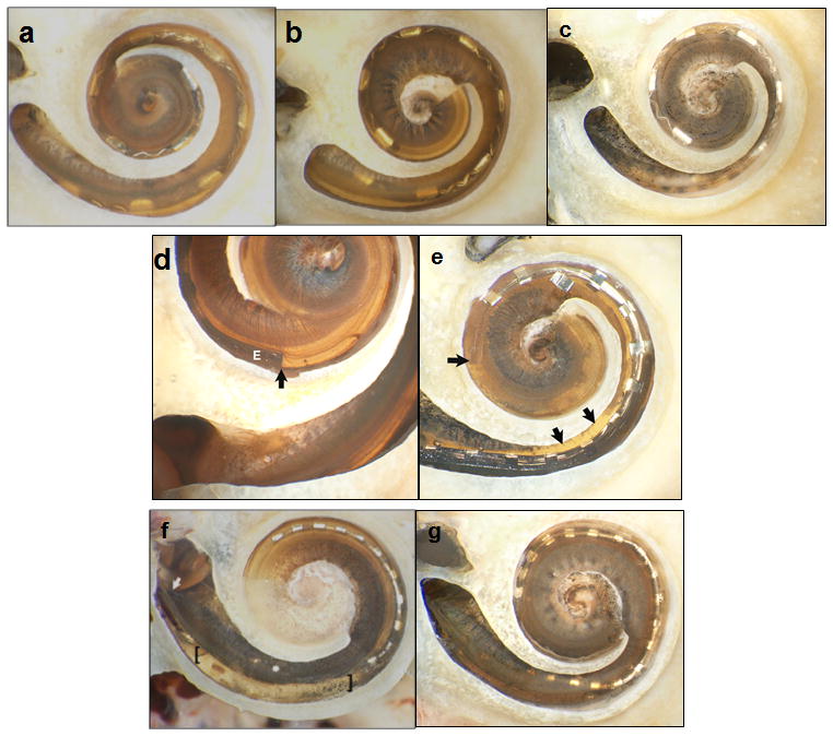
Histologic analysis with bone of promontory removed and basilar membrane (BM) in place. (a–c) Specimens 1–3 (Medel standard array electrodes) showed no intracochlear trauma, but incomplete insertion with 10, 8, and 8 electrodes intracochlear. (d–e) Specimens 4 and 5 (Advanced Bionics HiFocus 1J) had contrasting results with minimal trauma noted in Specimen 4 (d) where the tip of the electrode (marked as E) is noted with the dark and a subtle tear of BM near the cochleostomy site was identifiable (difficult to appreciate in 2-D photographs). Specimen 5 (e) had significant trauma with penetration of the osseous spiral lamina (OSL) and insertion of the electrode completely in scala vestibuli; the arrows to the right indicate the OSL injury and the horizontal arrow indicates the tip in scala vestibule resting on the BM. (f–g) Specimens 6 and 7 were Cochlear SRA electrodes. Specimen 6 (f) had a significant fracture in the OSL just distal to the cochleostomy (starting point noted by the diagonal arrow) and subsequent injury to the BM in the area between the brackets. Specimen 7 (g) had a small tear in the BM just anterior to the round window.
The three Medel electrode arrays (Standard arrays) were all inserted within scala tympani with no identifiable trauma via histology. Specimen 1 (Figure 4(a)) was inserted approximately 500 degrees with 10 of the 12 electrodes intracochlear and slight elevation of the basilar membrane at the most apical point. Specimens 2 and 3 (Figures 4(b) and 4 (c)) were inserted just over 360 degrees with 8 of 12 electrodes intracochlear and no identifiable trauma.
The Advanced Bionics electrodes (HiFocus 1J) are shown in Figures 4(d) and 4 (e). Specimen 4 (Figure 4(d)) was inserted to just over 360 degrees with 14 of 16 electrodes intracochlear. A small tear of the basilar membrane was evident just distal to the cochleostomy, but all intracochlear electrodes remained within the scala tympani. The apical end of the darkly stained electrode array is labeled with a black vertical arrow. There is subtle elevation but no penetration of the basilar membrane. Specimen 5 (Figure 4(e)) was inserted to just under 360 degrees with 13 of 16 electrodes intracochlear. The third most apical electrode is physically damaged. The electrode penetrated the osseous spiral lamina (Figure 5) just anterior to the round window and remained in scala vestibuli.
Figure 5.
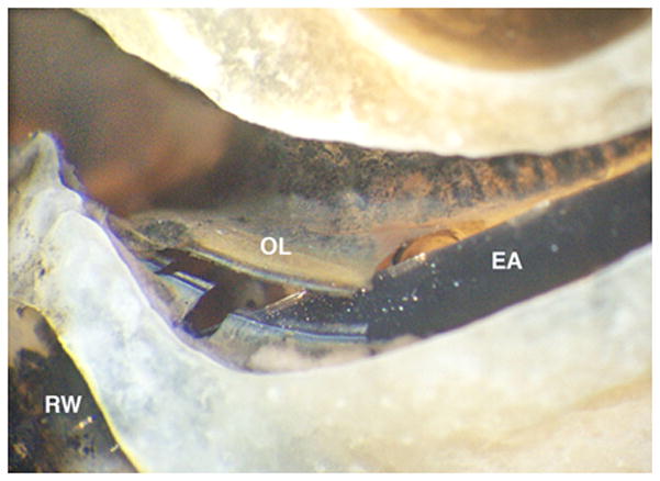
Close up hook region and intracochlear trauma in Specimen 5 (Figure 4(e)). The electrode array (EA) penetrates the osseous spiral lamina (OL) shortly after entering the cochlea via the marginal, round window (RW) cochleostomy.
The Cochlear electrodes (Straight Research Array) are shown in Figures 4(f) and 4 (g). Specimen 6 (Figure 4(f)) was inserted to approximately 300 degrees with 20 of 22 electrodes intracochlear. Notable was a fracture of the osseous spiral lamina in the basal turn leading to disruption of the basilar membrane within this region. The electrode array was inserted in scala tympani. Of note, this specimen was a difficult insertion requiring three attempts before successfully achieving electrode insertion. Specimen 7 (Figure 4(g)) was inserted 360 degrees with 21 of 22 electrodes intracochlear. All electrodes were within the scala tympani, but a slight tear of the basilar membrane was visible at the cochleostomy site.
Discussion
Prior to clinical implementation, we undertook the above study to model the complete steps of minimally-invasive, image-guided cochlear implantation. Cochlear implant electrode arrays felt to be amenable to this technique without the need for custom insertion tools (e.g. beyond those provided by the manufacturer) were chosen. As such, non-styleted, lateral wall electrodes were studied. We have previously reported on the use of a customized insertion tool for placement of styleted electrodes via the advance-off-stylet technique [20, 23]. Of note, the Cochlear SRA was a prototype for the now clinically available CI 422.
Surgical intervention was successfully completed for all specimens, where success was defined as avoidance of vital structures and insertion within the cochlea. Six of the seven electrode arrays (85%) were inserted into scala tympani. While five of the specimens (71%) had no or limited trauma, two of the specimens showed significant intracochlear trauma – one implanted with an Advanced Bionic HiFocus 1J array (Figure 4(e)) and one implanted with a Cochlear SRA (Figure 4(f)). Specimen 6 required repeated attempts to pass the electrode array. There was no visually identifiable cause for this difficulty with insertion. The intracochlear injury (Figure 6) appears to be due to either repeated attempts to insert the electrode or post-mortem tissue changes although inaccurate targeting by the proposed technology cannot be definitively excluded. More significant trauma was noted for Specimen 5, placed with the manufacturer’s insertion tool, as the electrode array crossed the basilar membrane leading to a sizeable injury to osseous spiral lamina. This initial injury was felt to be the cause of a displaced apical electrode. The cochleostomy and trajectory for this specimen appear to be as planned and in correct location (see Figure 5). As such, it is difficult to determine if this is related to the surgical technique (e.g. displacement of the apical electrode during transmission of the electrode array down the boney tunnel to the middle ear and/or upon entry into the cochlea) and whether a traditional cochlear implantation approach would have prevented such injury.
Figure 6.
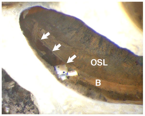
Close up of hook region and intracochlear trauma in Specimen 7. There is a tear (arrows) in the basilar membrane (B) and a white marker on the electrode array is visible. The osseous spiral lamina (OSL) is intact.
Regarding clinical significance, there are limited post-mortem histopathological analyses done on cochlear implant patients. Hence comparisons are difficult. While the histological results from this minimally-invasive, image-guided approach appear to be qualitatively better than the post mortem analysis reported by Nadol et al. [24, 25], those implants were performed nearly two decades ago before atraumatic technique was popularized. Perhaps a better basis for clinical comparison is violation of the basilar membrane which occurs most commonly when an electrode migrates from one scala to another. Published reports estimate the incidence of electrode migration to be approximately 30% with most of these violations occurring at approximately 180 degrees from the cochleostomy at the location where the electrode must first turn [24–28]. As only 1 of 7 specimens (15%) violated the basilar membrane, these findings would suggest that the minimally-invasive, image-guided approach may result in more accurate placement within scala tympani.
In contrast to other studies where injury is noted to occur at 180 degrees from the cochleostomy site [26, 27], we noted no trauma at this location. This may be due to the image-guided trajectory which aims to place the electrode array both within scala tympani and at an angle tangential to scala tympani in an effort to minimize cross-over. Making clinical interpretation of these injuries even more difficult is that the two injuries in our study occurred at the most proximal portion of the cochlea where high frequency hearing loss and neural loss is usually worst as opposed to the 180 degrees location where neural survival may be higher.
Our enthusiasm for accurate targeting of the scala tympani is somewhat dampened by the incomplete insertion of specimens notably Specimens 2 and 3 where only 8 of 12 electrodes were inserted. Our clinical practice aims to achieve complete insertion which we achieve routinely. As noted by others, including a publication by Roland, formalin-fixed temporal bone specimens suffer in that intracochlear fluid may be absent and tissue may be stiffer resulting in more difficult insertions [28]. Thus, we interpret our partial insertions as worst case scenarios. As the highly flexible Medel electrode resulted in the lowest number of intracochlear electrodes, we have worked with this manufacturer to create custom electrode arrays which include stiffening rods in the transmitting wire between the active electrodes and internal receiver. Preliminary, unpublished results suggest that this may allow more control and deeper insertion via the minimally-invasive, image-guided technique. Even if incomplete insertions would occur clinically, we note that, at worst, these insertions covered 360 degrees with at least 8 electrodes intracochlear, which is larger than the minimum (n=4) required for effective speech rehabilitation [29]. While future programming techniques may benefit from more and deeper intracochlear electrodes, other references suggest that deactivation does not adversely affect speech performance [30] and may actually improve speech performance by decreasing channel interaction [31, 32]. Nonetheless, our clinical goal with implementation of minimally-invasive, image-guided CI will be full electrode array insertion.
Conclusion
Using a cadaver model, we have shown that minimally-invasive, image-guided cochlear implantation surgery is feasible using standard electrode arrays. Only 1 of 7 specimens showed cross-over from scala tympani to scala vestibuli with 6 inserted within scala tympani. The most significant injury occurred when using an insertion tool provided by the implant manufacturer. Building on these findings we have undertaken clinical translation of this technique initially using lateral wall electrodes without insertion tools.
Footnotes
Conflict of Interests: Robert F. Labadie, MD, PhD is a consultant for Cochlear Corporation, Medel Corporation, and Ototronix. Drs. Dawant, Fitzpatrick, Noble, and Labadie hold intellectual property rights on aspects of the technology described herein some of which may lead to commercialization with the potential for financial benefit to them.
Financial Disclosures: The project described was supported by Award Number R01DC008408 and R01DC010184 from the National Institute on Deafness and Other Communication Disorders. The content is solely the responsibility of the authors and does not necessarily represent the official views of the National Institute on Deafness and Other Communication Disorders or the National Institutes of Health.
References
- 1.National Institute on Deafness and Other Communication Disorders. http://www.nidcd.nih.gov/health/hearing/pages/coch.aspx.
- 2.Kiratzidis T, Arnold W, Iliades T. Veria operation updated. I The trans-canal wall cochlear implantation. ORL. 2002;64:406–12. doi: 10.1159/000067578. [DOI] [PubMed] [Google Scholar]
- 3.Kronenberg J, Migirov L, Baumgartner W. The suprameatal approach in cochlear implant surgery: our experience with 80 patients. ORL. 2002;64:403–5. doi: 10.1159/000067576. [DOI] [PubMed] [Google Scholar]
- 4.Kronenberg J, Baumgartner W, Migirov L. The suprameatal approach: an alternative surgical approach to cochlear implantation. Otol Neurotol. 2004;25:41–5. doi: 10.1097/00129492-200401000-00008. [DOI] [PubMed] [Google Scholar]
- 5.Mann W, Gosepath J. Technical note: minimal access surgery for cochlear implantation with MedEl devices. ORL. 2006;68:270–2. doi: 10.1159/000093097. [DOI] [PubMed] [Google Scholar]
- 6.O’Donoghue G, Nikolopoulos T. Minimal access surgery for pediatric cochlear implantation. Otol Neurotol. 2002;23:891–4. doi: 10.1097/00129492-200211000-00014. [DOI] [PubMed] [Google Scholar]
- 7.Stratigouleas ED, Perry BP, King SM, et al. Complication rate of minimally invasive cochlear implantation. Otol Head Neck Surg. 2006;135:383–6. doi: 10.1016/j.otohns.2006.03.023. [DOI] [PubMed] [Google Scholar]
- 8.Warren FM, Balachandran R, Fitzpatrick JM, et al. Percutaneous cochlear access using bone-mounted, customized drill guides: demonstration of concept in vitro. Otol Neurotol. 2007;28:325–9. doi: 10.1097/01.mao.0000253287.86737.2e. [DOI] [PubMed] [Google Scholar]
- 9.Labadie RF, Mitchell JE, Balachandran R, et al. Customized, rapid-production microstereotactic table for surgical targeting: description of concept and in vitro validation. Int J CARS. 2009;4:273– 80. doi: 10.1007/s11548-009-0292-3. [DOI] [PMC free article] [PubMed] [Google Scholar]
- 10.Balachandran R, Mitchell JE, Blachon G, et al. Percutaneous Cochlear Implant Drilling via Customized Frames: an in vitro study. Otol-Head Neck Surg. 2010;142:421–426. doi: 10.1016/j.otohns.2009.11.029. [DOI] [PMC free article] [PubMed] [Google Scholar]
- 11.Labadie RF, Noble JH, Dawant BM, et al. Clinical validation of percutaneous cochlear implant surgery: initial report. Laryngoscope. 2008;118:1031–9. doi: 10.1097/MLG.0b013e31816b309e. [DOI] [PMC free article] [PubMed] [Google Scholar]
- 12.Labadie RF, Balachandran R, Mitchell J, et al. Clinical validation study of percutaneous cochlear access using patient customized microstereotactic frames. Otol Neurotol. 2009;31:94–9. doi: 10.1097/MAO.0b013e3181c2f81a. [DOI] [PMC free article] [PubMed] [Google Scholar]
- 13.Labadie RF, Chodhury P, Cetinkaya E, et al. Minimally invasive, image-guided, facial recess approach to the middle ear: Demonstration of the concept of percutaneous cochlear access in vitro. Otol Neurotol. 2005;26:557–62. doi: 10.1097/01.mao.0000178117.61537.5b. [DOI] [PubMed] [Google Scholar]
- 14.Balachandran R, Schurzig D, Fitzpatrick JM, et al. Evaluation of portable CT scanners for otologic image-guided surgery. IJCARS. 2012;7(2):315–21. doi: 10.1007/s11548-011-0639-4. [DOI] [PMC free article] [PubMed] [Google Scholar]
- 15.Noble JH, Warren FM, Labadie RF, et al. Automatic segmentation of the facial nerve and chorda tympani in CT images using spatially dependent feature values. Med Phys. 2008;35:5375– 84. doi: 10.1118/1.3005479. [DOI] [PMC free article] [PubMed] [Google Scholar]
- 16.Noble JH, Dawant BM, Warren FM, et al. Automatic identification and 3D rendering of temporal bone anatomy. Otol Neurotol. 2009;30:436– 42. doi: 10.1097/MAO.0b013e31819e61ed. [DOI] [PMC free article] [PubMed] [Google Scholar]
- 17.Noble JH, Majdani O, Labadie RF, Dawant B, Fitzpatrick JM. Automatic determination of optimal linear drilling trajectories for cochlear access accounting for drill-positioning error. Int J Med Robot. 2010;6(3):281–90. doi: 10.1002/rcs.330. [DOI] [PMC free article] [PubMed] [Google Scholar]
- 18.Liu X, Cevikalp H, Fitzpatrick JM. Marker orientation in fiducial registration. Proc. SPIE Medical Imaging; 2003; San Diego, CA. Feb, 2003. pp. 1176–1185. [Google Scholar]
- 19.Maes F, Collignon A, Vandermeulen D, et al. Multimodality image registration by maximization of mutual information. IEEE Trans Med Imaging. 1997;16:187–98. doi: 10.1109/42.563664. [DOI] [PubMed] [Google Scholar]
- 20.Kratchman LB, Schurzig D, McRackan TR, et al. A Manually-Operated, Advance Off Stylet Insertion Tool for Minimally-Invasive Cochlear Implantation Surgery. IEEE Trans Biomed Eng. 2012;59(10):2792–2800. doi: 10.1109/TBME.2012.2210220. [DOI] [PMC free article] [PubMed] [Google Scholar]
- 21.Schuman T, Noble J, Wright G, et al. Anatomic verification of a novel, non-rigid registration method for precise intrascalar localization of cochlear implant electrodes in adult human temporal bones using portable computerized tomography. Laryngoscope. 2010;120:2277–83. doi: 10.1002/lary.21104. [DOI] [PMC free article] [PubMed] [Google Scholar]
- 22.Wright CG, Roland PS. Temporal bone microdissection for anatomic study of cochlear implant electrodes. Coch Imp Int. 2005;6:159–68. doi: 10.1179/cim.2005.6.4.159. [DOI] [PubMed] [Google Scholar]
- 23.Schurzig D, Webster RJ, Dietrich MS, Labadie RF. Force of cochlear implant electrode insertion performed by a robotic insertion tool: comparison of traditional versus advance-off stylet techniques. Otology & Neurotology. 2010 Oct;31(8):1207–1210. doi: 10.1097/MAO.0b013e3181f2ebc3. [DOI] [PMC free article] [PubMed] [Google Scholar]
- 24.Nadol JB, Jr, Ketten DR, Burgess BJ. Otopathology in a case of multichannel cochlear implantation. Laryngoscope. 1994;104:299–303. doi: 10.1288/00005537-199403000-00010. [DOI] [PubMed] [Google Scholar]
- 25.Nadol JB, Jr, Shiao JY, Burgess BJ, et al. Histopathology of cochlear implants in humans. Ann Otol Rhinol Laryngol. 2001;110(9):883–91. doi: 10.1177/000348940111000914. [DOI] [PubMed] [Google Scholar]
- 26.Finley CC, Holden TA, Holden LK, et al. Role of electrode placement as a contributor to variability in cochlear implant outcomes. Otol Neurotol. 2008;29:920–28. doi: 10.1097/MAO.0b013e318184f492. [DOI] [PMC free article] [PubMed] [Google Scholar]
- 27.Wanna GB, Noble JH, McRackan TR, et al. Assessment of Electrode Placement and Audiological Outcomes in Bilateral Cochlear Implantation. Otology & Neurotology. 2011;32:482–32. doi: 10.1097/MAO.0b013e3182096dc2. [DOI] [PMC free article] [PubMed] [Google Scholar]
- 28.Roland JT. A Model for Cochlear Implant Electrode Insertion and Force Evaluation: Results with a New Electrode Design and Insertion Technique. Laryngoscope. 2005;115:1325–39. doi: 10.1097/01.mlg.0000167993.05007.35. [DOI] [PubMed] [Google Scholar]
- 29.Shannon RV, Zeng F-G, Wygonski J. Speech recognition with altered spectral distribution of envelope cues. Journal of the Acoustical Society of America. 1996;100:2468–76. doi: 10.1121/1.423774. [DOI] [PubMed] [Google Scholar]
- 30.Zeitler DM, Lalwani AK, Roland JT, Jr, Habib MG, Gudis D, Waltzman SB. The effects of cochlear implant electrode deactivation on speech perception and in predicting device failure. Otology & Neurotology. 2009;30(1):7–13. doi: 10.1097/MAO.0b013e31818a08ba. [DOI] [PubMed] [Google Scholar]
- 31.Holden LK, Reeder RM, Firszt JB, Finley CC. Optimizing the perception of soft speech and speech in noise with the Advanced Bionics cochlear implant systm. In J Audiol. 2011;50(4):255–269. doi: 10.3109/14992027.2010.533200. [DOI] [PMC free article] [PubMed] [Google Scholar]
- 32.Noble JH, Labadie RF, Gifford RH, Dawant BM. Image-guidance enables new methods for customizing cochlear implant stimulation strategies. IEEE Trans on Neural Systems and Rehabilitation Engineering. doi: 10.1109/TNSRE.2013.2253333. in press. [DOI] [PMC free article] [PubMed] [Google Scholar]


