Abstract
This paper presents the performance characterization of the MAHI Exo-II, an upper extremity exoskeleton for stroke and spinal cord injury (SCI) rehabilitation, as a means to validate its clinical implementation and to provide depth to the literature on the performance characteristics of upper extremity exoskeletons. Individuals with disabilities arising from stroke and SCI need rehabilitation of the elbow, forearm, and wrist to restore the ability to independently perform activities of daily living (ADL). Robotic rehabilitation has been proposed to address the need for high intensity, long duration therapy and has shown promising results for upper limb proximal joints. However, upper limb distal joints have historically not benefitted from the same focus. The MAHI Exo-II, designed to address this shortcoming, has undergone a static and dynamic performance characterization, which shows that it exhibits the requisite qualities for a rehabilitation robot and is comparable to other state-of-the-art designs.
Introduction
Stroke is the fourth leading cause of death in the United States, and its social and economic effects are widespread. By 2030, it is estimated that nearly four percent of adults will have had a stroke. The economic costs stemming from stroke treatment are estimated to rise from $71.55 billion in 2010 to $183.13 billion in 2030. A significant portion of these costs is associated with rehabilitation, which comprises 16% of the total expenses incurred in the immediate 90 days following a stroke [1]. Therefore, a significant social and economic impact can be made through the improvement of rehabilitative measures.
In recent decades, robotic rehabilitation has generated substantial interest in the medical and rehabilitation fields. Studies have shown empirically that repetitive, robot-aided therapy is effective for regaining a degree of motor function in the limbs impaired by stroke or spinal cord injury [2, 3]. Robots are effective for improving rehabilitation outcomes and conducting rehabilitation research. These devices, which are designed for a range of different objectives, in general possess the ability to quantify patient improvement over time. These improvements include quantitative metrics such as range of motion (ROM), movement smoothness, and strength, which are essential feedback to therapists and researchers in robot design and control.
Classification of Rehabilitation Robots
Rehabilitation robots can be broadly classified into two categories: end-effectors and exoskeletons. In the rehabilitation sense, an end-effector is a device that attaches to the patient's limb at one point, the most distal part of the robot. Well-known examples of end effector robots include the planar, 2 degrees-of-freedom (DOF) MIT-Manus [4], as well as the 3-DOF ARM Guide [5], and the Mirror Image Movement Enabler (MIME) [6].
Exoskeletons, on the other hand, have at least two points of contact. Unlike end-effector robots, exoskeletons allow for the application of torques at individual body joints because there is a mapping between the joints of the exoskeleton and the joints of interest of the subject, which are usually aligned by design. Their designs range from simple 1-DOF devices such as the mPower Arm Brace (Myomo, Inc.) to multiple DOF devices such as the ARMin III [7], CADEN 7 [8], and the RiceWrist [9].
Characterization of Rehabilitation Robots
Before any clinical implementation, analysis of a rehabilitation robot's performance is necessary to validate it as a suitable platform for rehabilitation and research. As detailed previously [10], a rehabilitation robot must exhibit certain key characteristics, including: i) functional workspace and closed-loop position bandwidth spanning the requirements for the trained activities [11], ii) the capacity for torque application to specific human joints [11] and for quantitative evaluation of treatment [12] iii) high backdrivability with no backlash [13], and iv) the ability to implement advanced control algorithms [14]. Parameters such as static and viscous friction, inertia, closed-loop position bandwidth, spatial resolution, ROM, and torque output are used to evaluate a rehabilitation robot.
The literature on the characterization of novel upper extremity exoskeletons does not always provide all of the previous metrics. To address this shortcoming in the literature, the newly presented performance characterization of the MAHI Exo-II put forward here was chosen to match the detailed characterization presented by Pehlivan, et al. [10] and be similar to that presented by Krebs, et al. [15]. Creating complementary characterizations allows for direct comparison of these upper extremity exoskeletons, and creates a basis for comparison with future designs.
This paper reviews the mechanical design of the MAHI Exo-II, to present new design modifications and to provide background for the following characterization. The performance characterization focuses on quantifying how the MAHI Exo-II addresses the four requirements of rehabilitation robots, by investigating first the static friction of the device. Static friction perturbs movement, which can be overcome in control, but not when the robot is being backdriven, as is common during subject assessments, and should therefore be minimized. Likewise, inertia and viscous friction negatively affect backdrivability, and they are more problematic to eliminate in control schemes. Next, the closed-loop bandwidth of the device is established, which further supports how well the exoskeleton matches healthy human capabilities. The performance characterization concludes with determining the device's spatial resolution, which should be optimized in order to provide accurate subject assessment. A discussion of the results and future work for the exoskeleton follows, along with the conclusions drawn from the characterization.
Mechanical Design of the MAHI EXO-II
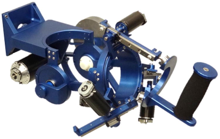
The MAHI Exo-II is an upper extremity exoskeleton, first presented in 2004 [16] with four active DOF, including elbow flexion-extension (F/E), forearm pronation-supination (P/S), wrist F/E and radial-ulnar deviation (R/U), and one passive DOF (shoulder abduction and adduction for the user's comfort). In this paper, we present a more robust version of the MAHI Exo-II designed for use in a clinical setting. The previous iteration's design [17] was modified in a few ways to improve its suitability for clinical implementation, namely, the addition of a mechanical hard stop to the elbow DOF as a redundant safety measure, reduction of transmission ratios, and the use of higher resolution quadrature encoders (2,048 counts per revolution). The exoskeleton can be position or force controlled [9] through a real-time Windows target running Simulink® and Quarc® at 1 kHz. Data acquisition is accomplished with a Q-8 USB, and linear servoamplifiers provide current control of the actuators. Newly investigated force feedback control schemes include incorporating grip force sensing [18] and series-elastic actuation [19].
For reference, the ROM and torque required to complete ADL and the corresponding outputs of the MAHI Exo-II are summarized in Table 1, along with two other wrist designs for comparison. Note that the torque values listed for all exoskeletons are the maximum torque values. The elbow DOF consists of a revolute joint that is actuated by a brushed Maxon Re-65 DC motor (part no. 353297) attached via low-stretch nylon coated cable to a capstan arc, delivering a transmission ratio of approximately 10.7:1. The forearm DOF also consists of a revolute joint actuated by a Maxon Re-40 DC motor (part no. 148877) and cable drive that deliver a transmission ratio of approximately 14.7:1. The wrist module is a parallel mechanism actuated by three Maxon Re-35 DC motors (part no. 273761) that extend and retract rigid links via cable drives for a transmission ratio of 27.2 rotations to 1 meter of extension/retraction. The basic kinematic structure is a 3-revolute-prismatic-spherical (RPS) mechanism, discussed extensively in the literature [20].
Table 1.
ROM and Torque of ADL [21], MAHI Exo-II, RiceWrist-S [22], and Wrist module of the MIT-Manus [15]. The values listed in parentheses for ME-II are for the Previously Presented MAHI Exo-II Design [17]
| Range of Motion (deg) | Torque (Nm) | |||||||
|---|---|---|---|---|---|---|---|---|
| Joint | ADL | ME-II | RW-S | MIT | ADL | ME-II | RW-S | MIT |
| Elbow F/E | 150 | 90 (90) | — | — | 3.5 | 7.35 (11.61) | — | — |
| Forearm P/S | 150 | 180 (180) | 180 | 140 | 0.06 | 2.75 (2.3) | 1.69 | 1.85 |
| Wrist F/E | 115 | 65 (72) | 130 | 120 | 0.35 | 1.45 (1.67) | 3.37 | 1.43 |
| Wrist R/U | 70 | 63 (72) | 75 | 75 | 0.35 | 1.45 (1.93) | 2.11 | 1.43 |
Characterization of Performance
We present the experimentally determined performance characteristics of the MAHI Exo-II, including static friction, inertia, viscous friction, spatial resolution, and closed-loop position bandwidth, summarized in Table 2. For each test, gravitational effects were eliminated by orienting the exoskeleton so that the axis of rotation of the DOF of interest was aligned with the direction of gravity. All tests on the parallel mechanism were performed at a platform height (distance between base plate and wrist ring) of 9 cm, typical for the average user.
Table 2.
| Joint | Static Friction (Nm) |
Inertia (kg·m2) |
Viscous Friction |
CL Pos. BW (Hz) |
||||||
|---|---|---|---|---|---|---|---|---|---|---|
| ME-II | RW-S | MIT | ME-II | RW-S | MIT | ME-II | RW-S | ME-II | RW-S | |
| E. F/E | 0.9491 (12.9%) | — | — | 0.2713 | — | — | 0.1215 | — | 2.8 | — |
| F. P/S | 0.139 (5.1%) | 0.221 (13.1%) | 0.29 (15.7%) | 0.0257 | 0.0258 | 0.0058 | 0.0167 | 0.428 | 4.2 | 3.5 |
| W. F/E | 0.109 (7.5%) | 0.198 (5.9%) | 0.075 (5.2%) | 0.002 | 0.01165 | 0.0040 | 0.0283 | 0.085 | 13.3 | 6 |
| W. R/U | 0.112 (7.7%) | 0.211 (10%) | 0.075 (5.2%) | 0.0033 | 0.0048 | 0.0031 | 0.0225 | 0.135 | 10.6 | 8.3 |
Static Friction
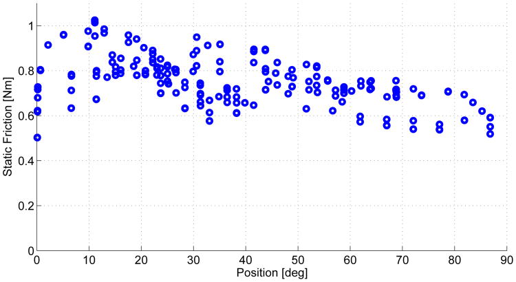
To investigate static friction, we implemented proportional control acting on a custom movement profile. This profile consisted of setting the desired joint position to continuously ramp up for a period of 3 seconds (for elbow F/E and forearm P/S) or 5 seconds (for wrist F/E and R/U), pause at a constant desired position for the same duration, and then repeat. For each DOF, the slope and duration of each ramp was held constant to slowly gather data across the workspace. Static friction was computed by logging the task-space torque at which the joint's angular velocity became nonzero. An example plot of this data for the elbow joint is shown in Fig. 2. Note that the minimum stiction values at the extremes of the workspace (when the joint reversed direction) were discarded to provide a more conservative (higher) estimate of static friction. Even with the more conservative estimate, the static friction, as a percentage of continuous torque output, remains small (no more than 12.9% for any DOF). Table 2 reports the maximum static friction for the RiceWrist-S, the wrist module of the MIT-MANUS, and each serial DOF of the MAHI Exo-II (elbow F/E and forearm P/S), along with the percentage of maximum continuous torque it represents in parentheses. For the parallel DOFs (wrist F/E and R/U) of the MAHI Exo-II, the static friction values were averaged due to the geometry of the parallel mechanism which allows gravity to perform virtual work even when the axis of rotation is aligned with (and therefore the direction of the movement is perpendicular to) the direction of gravity. Note that maximum torque for the parallel mechanism is a function of orientation, and the torque maximums reported in Table 2 are the maximum possible output of the wrist mechanism.
Figure 2.
Torque Commanded the Moment the Elbow Joint Overcame Static Friction, Versus Position.
Inertia and Viscous Friction
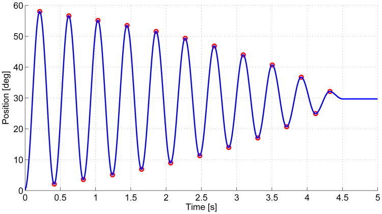
To investigate the viscous friction and inertia characteristics of the device, we analyzed the step response of each DOF. Again, we implemented proportional control and used a logarithmic decrement method that isolates the inertial and viscous effects by iteratively characterizing sequential peaks and troughs [23]. The step response of the forearm DOF is shown in Fig. 3 as an example. As seen in Table 2, inertia of the elbow DOF is high, which is partially due to the counterweight, used as passive gravity compensation for the weight of the exoskeleton and the user's arm. This design choice was made to avoid the cost of compensating via the elbow DOF actuator, reducing the torque available for rehabilitation in flexion movements.
Figure 3.
Step Response from 0° to 30° for Forearm p/s. the peaks and Troughs are Indicated in Red.
Closed-loop Position Bandwidth
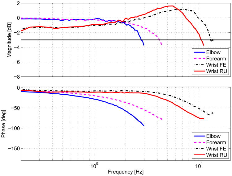
To determine closed-loop position bandwidth, we commanded the robot to track a constant magnitude (10°) chirp signal trajectory. The sine sweep began at 0.1 Hz and slowly increased until sufficient output attenuation was reached. The stiffness (Kp) and damping (Kd) gains used for this trajectory tracking were the same gains that produced a critically damped step response. The frequency responses for each DOF are shown in Fig 4. This characterization shows that the MAHI Exo-II exhibits bandwidth in the elbow and forearm DOF within the range of human capability and that the wrist DOFs exceed human capability, in general established to be between 2 and 5 Hz [24]. Specifically, arm movements that demand the precise application of high force and high frequency, such as competitive curling, are typically less than 5 Hz for elite players [25]. For the purpose of restoring specialized movements such as these, or the ability to independently perform ADL, all DOF are more than adequate.
Figure 4.
Frequency Response for each DOF.
Spatial Resolution
The spatial resolution of the MAHI-Exo II was determined by using the Jacobian evaluated at 10,000 points arranged in a linearly spaced grid encompassing the workspace. The worst case scenario minimum detectable change was determined to be 7.159 × 10⁻⁵, 5.216 × 10⁻⁵, 1.313 × 10⁻⁴, and 1.219 × 10⁻⁴ radians for elbow flexion/extension, forearm pronation/supination, wrist flexion/extension, and wrist radial/ulnar deviation, respectively. This spatial resolution is on the same order as the RiceWrist-S [22], and the backlash-free capstan transmissions will allow for highly accurate subject assessment.
Discussion
Rehabilitation robot performance can be evaluated with several characteristics, such as static and viscous friction, inertia, and closed-loop position bandwidth. Specifically, the MAHI Exo-II exhibits favorable static friction characteristics, both in magnitude and as a percentage of maximum continuous torque output, and its relatively constant magnitude enables effective compensation via feedforward techniques. Both the inertial and viscous friction characteristics of the device are suitable for administering high quality therapy, however, future designs would benefit from the use of advanced composites in the distal elements of the exo, along with a less inertial method for elbow DOF gravity compensation. Closed-loop bandwidth tests showed that the device has capabilities to match healthy human movement; however, future tests could benefit from the utilization of input signals with flat power spectrums, instead of a sine chirp, for more accurate frequency responses. As shown in Tables 1 and 2, the MAHI Exo-II has capabilities comparable to other state-of-the-art serial wrist exoskeletons [15]. In comparison to the RiceWrist-S, the parallel mechanism of the MAHI Exo-II offers lower inertia, viscous coefficient, and static friction, but has reduced torque output and workspace.
Conclusion
The MAHI Exo-II meets the requirements for high performance rehabilitation exoskeletons. In particular, it possesses the workspace, torque outputs and bandwidth to match human capabilities, low inertia, static friction and viscous damping that will result in high backdrivability, and the hardware capabilities to complement the implementation of complex control.
Figure 1. MAHI Exo-II, A 5-DOF Powered Exoskeleton.

Contributor Information
James A. French, Email: jaf12@rice.edu.
Chad G. Rose, Email: cgr2@rice.edu.
Marcia K. O'Malley, Email: omalleym@rice.edu.
References
- 1.Ovbiagele B, et al. Forecasting the future of stroke in the United States: a policy statement from the American Heart Association and American Stroke Association. Stroke. 2013 Aug;44(8):2361–75. doi: 10.1161/STR.0b013e31829734f2. [DOI] [PubMed] [Google Scholar]
- 2.Krebs H, Hogan N, Aisen M, Volpe BT. Robot-aided neurorehabilitation. IEEE Trans Rehabil Eng. 1998;6(1):75–87. doi: 10.1109/86.662623. [DOI] [PMC free article] [PubMed] [Google Scholar]
- 3.Yozbatiran N, Berliner J, O'Malley MK, Pehlivan AU, Kadivar Z, Boake C, Francisco GE. Robotic training and clinical assessment of upper extremity movements after spinal cord injury: a single case report. Journal of Rehab Med. 2012 Feb;44(2):186–8. doi: 10.2340/16501977-0924. [DOI] [PubMed] [Google Scholar]
- 4.Charles SK, Krebs HI, Volpe BT, Lynch D, Hogan N. Wrist rehabilitation following stroke: initial clinical results. proc of IEEE Intl Conf on Rehab Robotics (ICORR) 2005:13–16. [Google Scholar]
- 5.Reinkensmeyer DJ, Kahn LE, Averbuch M, McKenna-Cole A, Schmit BD, Rymer WZ. Understanding and treating arm movement impairment after chronic brain injury: Progress with the ARM guide. J of Rehabil Res Dev. 2000;37(6):653–662. [PubMed] [Google Scholar]
- 6.Lum PS, Burgar CG, Loos MVD, Shor PC, Ma-jmundar M, Yap R. MIME robotic device for upper-limb neurorehabilitation in subacute stroke subjects: A follow-up study. J Rehabil Res and Dev. 2006;43(5):631–642. doi: 10.1682/jrrd.2005.02.0044. [DOI] [PubMed] [Google Scholar]
- 7.Nef T, Guidali M, Riener R. ARMin III arm therapy exoskeleton with an ergonomic shoulder actuation. Applied Bionics and Biomechanics. 2009 Jul;6(2):127–142. [Google Scholar]
- 8.Perry JC, Rosen J. Design of a 7 degree-of-freedom upper-limb powered exoskeleton. proc of IEEE BioRob. 2006:805–810. [Google Scholar]
- 9.Gupta A, O'Malley MK, Patoglu V, Burgar C. Design, control and performance of RiceWrist: a force feedback wrist exoskeleton for rehabilitation and training. The Intl J Robot Res. 2008 Feb;27(2):233–251. [Google Scholar]
- 10.Pehlivan AU, Rose C, O'Malley MK. System characterization of ricewrist-s: a forearm-wrist ex-oskeleton for upper extremity rehabilitation. proc of the IEEE Intl Conf on Rehab Robotics (ICORR) 2013 doi: 10.1109/ICORR.2013.6650462. [DOI] [PubMed] [Google Scholar]
- 11.Schiele A, van der Helm FC. Kinematic design to improve ergonomics in human machine interaction. IEEE Trans Neural Syst Rehabil Eng. 2006;14(4):456–469. doi: 10.1109/TNSRE.2006.881565. [DOI] [PubMed] [Google Scholar]
- 12.Celik O, O'Malley MK, Boake C, Levin HS, Yozbatiran N, Reistetter TA. Normalized movement quality measures for therapeutic robots strongly correlate with clinical motor impairment measures. IEEE Trans Neural Syst and Rehabil Eng. 2010;18(4):433–444. doi: 10.1109/TNSRE.2010.2047600. [DOI] [PMC free article] [PubMed] [Google Scholar]
- 13.Hayward V, Maclean K. Do it yourself haptics: part I. IEEE Robotics & Automation Magazine. 2007 Dec;14(4):88–104. [Google Scholar]
- 14.Wolbrecht ET, Chan V, Reinkensmeyer DJ, Bo-brow JE. Optimizing compliant, model-based robotic assistance to promote neurorehabilitation. IEEE Trans Neural Syst Rehabil Eng. 2008;16(3):286–297. doi: 10.1109/TNSRE.2008.918389. [DOI] [PubMed] [Google Scholar]
- 15.Krebs H, Volpe BT, Williams D, Celestino J, Charles SK, Lynch D, Hogan N. Robot-aided neurorehabilitation : a robot for wrist rehabilitation. IEEE Trans Neural Syst Rehabil Eng. 2007;15(3):327–335. doi: 10.1109/TNSRE.2007.903899. [DOI] [PMC free article] [PubMed] [Google Scholar]
- 16.Gupta A, O'Malley MK. Design of a haptic arm exoskeleton for training and rehabilitation. IEEE/ASME Trans Mechatronics. 2006;11(3):280–289. [Google Scholar]
- 17.Pehlivan AU, Celik O, O'Malley MK. Mechanical design of a distal arm exoskeleton for stroke and spinal cord injury rehabilitation. proc of the IEEE Intl Conf on Rehab Robotics (ICORR) 2011:633–637. doi: 10.1109/ICORR.2011.5975428. [DOI] [PubMed] [Google Scholar]
- 18.Erwin A, Sergi F, Chawda V, OMalley MK. Interaction control for rehabilitation robotics via a low-cost force sensing handle. proc of the 6th Annual ASME Dynamic Systems and Controls Conference (DSCC) 2013 doi: 10.1115/DSCC2013-4073. [DOI] [Google Scholar]
- 19.Sergi F, Lee MM, O'Malley MK. Design of a series elastic actuator for a compliant parallel wrist rehabilitation robot. proc of IEEE Intl l Conf on Rehab Robotics (ICORR) 2013 doi: 10.1109/ICORR.2013.6650481. [DOI] [PubMed] [Google Scholar]
- 20.Lee K, Shah D. Kinematic analysis of a three-degrees-of-freedom in-parallel actuated manipulator. IEEE Journal of Robotics and Automation. 1988;4(3):354–360. [Google Scholar]
- 21.Perry JC, Rosen J, Burns S. Upper-limb powered exoskeleton design. IEEE/ASME Trans on Mechatronics. 2007 Aug;12(4):408–417. [Google Scholar]
- 22.Pehlivan AU, Sergi F, Erwin A, Yozbatiran N, Francisco GE, O'Malley MK. Design and validation of the RiceWrist-S exoskeleton for robotic rehabilitation after incomplete spinal cord injury. Robotica. 2014 doi: 10.1017/S0263574714001490. Available on CJO 2014. [DOI] [Google Scholar]
- 23.Liang JW, Feeny BF. Identifying coulomb and viscous friction from free-vibration decrements. Nonlinear Dynamics. 1998;16:337–347. [Google Scholar]
- 24.Brooks TL. Telerobotic response requirements. proc of IEEE Intl Conf on Systems, Man, and Cybernetics. 1990:113–120. [Google Scholar]
- 25.Bradley JL. The sports science of curling: a practical review. Journal of sports science & medicine. 2009 Jan;8(4):495–500. [PMC free article] [PubMed] [Google Scholar]


