

Abstract
Objectives:
Controversy exists regarding cavity preparation for restoration of interproximal caries in posterior teeth in terms of preserving the tooth structure and suitable stress distribution. This study aimed to assess the effect of extension and type of class II cavities and the remaining tooth structure in maxillary premolars restored with composite resin on the biomechanical properties of teeth using finite element method (FEM).
Materials and Methods:
Using FEM, eight three-dimensional (3D) models of class II cavities in maxillary premolars with variable mesiodistal (MD) dimensions, variable thickness of the residual wall in-between the mesial and distal cavities and different locations of the wall were designed. Other dimensions were the same in all models. Cavities were restored with composite resin. A load equal to the masticatory force (200N) was applied to the teeth. Finite element analysis (FEA) was used to calculate the von Mises stress.
Results:
Stress in the enamel margin increased by increasing the MD dimensions of the cavities. Deviation of the residual wall between the mesial and distal cavities from the tooth center was found to be an important factor in increasing stress concentration in the enamel. Increasing the MD dimensions of the cavity did not cause any increase in stress concentration in dentin.
Conclusion:
Increasing the MD dimensions of the cavities, decreasing the thickness of the residual wall between the mesial and distal cavities and its deviation from the tooth center can increase stress concentration in the enamel but not in dentin.
Keywords: Stress, Distribution, Composite restorations, Cavities, Biomechanical properties, Finite element analysis
INTRODUCTION
In the clinical setting, clinicians often encounter teeth that have lost most of their structure due to trauma, caries or cavity preparation. These teeth have decreased resistance to fracture [1–2]. Restorative dentists try to overcome this problem by using composite resins [3]. Composite resins are suitable alternatives to amalgam in stress bearing areas of the posterior teeth and benefit from chemical bonding to tooth structure. By chemically bonding to the cavity walls, composite resins reinforce the remaining tooth structure and increase fracture resistance [4–5].
Long-term success of composite restorations depends on the resistance of different components of this complex system such as the different surfaces and interfaces against stress and deformation [6]. Inappropriate stress distribution in restorations can further add to the stress due to polymerization shrinkage and compromise the bond at the interface causing secondary caries, pulp inflammation and necrosis and post-operative tooth hypersensitivity [6–8]. It may also cause cracks and tooth fracture [9]. Thus, the stress concentration must be minimal at the tooth-restoration interface by an ideal design of cavities in order to prevent marginal ditching and debonding at the tooth-restoration interface and increase restoration survival. The survival of composite restorations depends on the type of restoration, number of bonded surfaces, size of the cavity and type of restored tooth [10]. Premolar teeth, due to their location in dental arch, are subjected to massive compressive and shear forces and have high prevalence of clinical fracture [11–12]. The incidence rate of fracture is higher in the maxillary compared to the mandibular premolars and is also greater in class II compared to class I cavities [13]. In class II cavities, strategic structures namely the marginal ridges are lost and by increasing the isthmus width, the remaining tooth structure is significantly decreased. Consequently, the tooth strength is significantly compromised and the flexibility of the cusps is considerably enhanced [14]. Evidence shows that different parameters in the prepared cavity including its depth and width play important roles in fracture resistance of the restored tooth and cusp fractures [1, 15]. Panitvisai and Misser (2012) showed that loss of the axial wall in a molar tooth is the most important factor decreasing cusp stiffness [8]. Another study demonstrated that loss of each tooth surface decreases tooth stiffness by approximately 20% [16]. Large mesio-occluso-distal (MOD) cavities in premolar teeth decrease the cusp stiffness by 1/3 of that in sound teeth. In MOD cavity preparation, depth of the axial wall and dentin thickness in-between the mesial and distal cavities are important criteria [17]. In a FEA by Khera et al, similar results were obtained regarding MOD cavities [18].
To reduce the risk of tooth fracture, stress distribution following the application of occlusal loads must be thoroughly evaluated based on the size and shape of the cavity particularly in extensive MOD cavities [7]. Due to high response rate, speed and accuracy, FEM can be widely used for quantitative assessment of biomechanical behaviors of complex structures that are susceptible to stress in different situations and under variable load applications [19, 20].
Considering the key role of premolar teeth in smile esthetics, improved characteristics of composites, high demand for tooth-colored restorations [21], and high clinical failure rate of these premolar restorations [11–12], it seems crucial to assess cavity design and stress distribution in different tooth surfaces [21]. Previous studies have mostly focused on the effect of increased width and depth of isthmus of prepared cavities on stress distribution in the enamel and dentin [3,22] and number of studies on the effect of the thickness of the residual wall between the mesial and distal cavities on stress distribution at the interface is scarce. The FEM, originally used in structural analysis, has changed dental biomechanical research. FEM is a numerical method to calculate various parameters when complex structures are loaded. This method has proven its efficacy in different situations [23–27].
This study sought to assess the stress distribution mode at the interface in different class II cavity designs with variable thicknesses of the residual wall between the mesial and distal cavities of maxillary premolar teeth using FEM.
This study aimed to find an ideal class II cavity design with the lowest risk of fracture for maxillary premolar teeth.
MATERIALS AND METHODS
To analyze stress distribution, FEM and SolidWorks 2006 software (Dassault Systems S.A., Concord, MA, USA) were used to prepare eight 3D models of the maxillary premolar teeth with all the anatomical and morphological details. Different parts of the tooth including pulp, dentin, cementum and enamel and adjacent anatomical structures including the periodontal ligament, spongy bone and cortical bone were designed. Different models of class II cavities with different occlusal extensions were prepared in teeth in the two groups of symmetric and asymmetric models (Table 1, Figures 1-a to 1-h).
Table 1.
Designed different models of class II cavities with different occlusal extensions in maxillary premolar
| Number of model | Type of cavities | Depth of box | BL *width of box | MD**width of box | depth of occlusal cavity | BL width of occlusal cavity | MD width of occlusal cavity |
|---|---|---|---|---|---|---|---|
| 1 | Two mesial and distal single boxes | 5.2 mm$ | 5 mm | 2 mm | - | - | - |
| 2 | MO# and DO## cavities | 5.2 mm | 5 mm | 2 mm | 2 mm | 1/3 of the inter-cuspal distance | 0.5 mm |
| 3 | MO and DO cavities | 5.2 mm | 5 mm | 2 mm | 2 mm | 1/3 of the inter-cuspal distance | 1 mm |
| 4 | MO and DO cavities | 5.2 mm | 5 mm | 2 mm | 2 mm | 1/3 of the inter-cuspal distance | 1.25 mm |
| 5 | a MOD^ cavity | 5.2 mm | 5 mm | 2 mm | 2 mm | 1/3 of the inter-cuspal distance | - |
| 6 | distal single box and a MO cavity | 5.2 mm | 5 mm | 2 mm | 2 mm | 1/3 of the inter-cuspal distance | 1.5 mm |
| 7 | distal single box and a MO cavity | 5.2 mm | 5 mm | 2 mm | 2 mm | 1/3 of the inter-cuspal distance | 2 mm |
| 8 | distal single box and a MO cavity | 5.2 mm | 5 mm | 2 mm | 2 mm | 1/3 of the inter-cuspal distance | 2.5 mm |
BL: Buccolingual
MD: Mesiodistal
MO: Mesio-occlusal
DO: Disto-occlusal
MOD: mesio-occluso-distal
mm: millimeter
Fig 1.
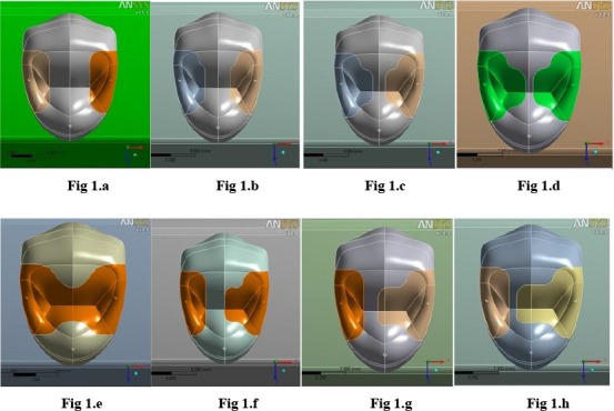
Designed Models
Models 1 to 4 had a symmetric design, model 5 depicted a MOD cavity and models 6–8 had asymmetric design.
The box pattern and occlusal extension were in accord with the study by Lopez et al [14]. In their study, all models were designed with round internal and external line angles to prevent false stresses and eliminate the effect of confounders on the results. Next, all cavities were restored with composite resin. Models were then transferred to ANSYS Workbench Ver.12.1 software (ANSYS Inc., PA, USA) for calculations.
The models were meshed between 19,033 and 23,675 nodes and 9,931 to 12,654 elements (Table 2, Fig 2.). As boundary condition, all nodes at the base of the models were restrained so that all rigid bodily motions were prevented.
Table 2.
Number of nodes and elements in each model
| Models | Number of nodes | Number of elements |
|---|---|---|
| Model 1 | 19033 | 9931 |
| Model 2 | 22984 | 12268 |
| Model 3 | 23557 | 12611 |
| Model 4 | 23675 | 12654 |
| Model 5 | 20262 | 10615 |
| Model 6 | 21528 | 11408 |
| Model 7 | 19803 | 10301 |
| Model 8 | 20028 | 10468 |
Fig 2.

Limited element network model
The models were then transferred to limited element program to produce limited element networks. The next step included uploading the mechanical properties of each structure and choosing the loading conditions. All the living tissues were presumed to be elastic, homogenous and isotropic. Then, the respective elastic properties namely the Young's modulus, and the Poisson's ratio were defined for different parts of the tooth, composite and the neighboring anatomical structures according to Table 3 [28]. Compressive load equal to the masticatory load (200N) was applied along the long axis of the tooth to the buccal cusp tip and mesial and distal marginal ridges (Table 3) [28]. The Von Misses stress distribution was investigated in dentin and enamel.
Table 3.
The Young's modulus and the Poisson's ratio of the materials
| Materials | Young's modulus (MPa) | Poisson's ratio |
|---|---|---|
| Enamel | 84100 | 0.20 |
| Dentin | 18600 | 0.31 |
| Pulp | 2 | 0.45 |
| Composite resin | 6700 | 0.22 |
| Periodontal ligament | 70 | 0.45 |
| Spongy bone | 1500 | 0.30 |
| Cortical bone | 15000 | 0.30 |
RESULTS
Stress concentration at the residual wall enamel margin (tooth-restoration interface) between the mesial and distal cavities:
Graph 1.a. shows the stress concentration at the enamel margin of the inter-axial wall in symmetric models with equal dimensions of mesial and distal cavities.
Graph 1.a.

Stress at the enamel margin in symmetric models
Graph 1.b. shows the stress concentration at the margin of the inter-axial wall in asymmetric models with different dimensions of mesial and distal cavities.
Graph 1.b.

Stress at the enamel margin in asymmetric models
Occlusal view of stress distribution:
Figures 12 and 13 show the effect of decreasing the thickness of the residual wall between the mesial and distal cavities from 2 mm to 0.5 mm on stress distribution and the difference in stress distributed in symmetric (right) and asymmetric (left) models.
Stress concentration in MO cavities and distal boxes of asymmetric models:
Graph 2.a. depicts stress concentration at the tooth-restoration interface in MO cavities of asymmetric models. In these models, the highest amount of stress was concentrated at the enamel margin followed by an area close to the deepest point of the mesial wall at the dentino-enamel junction (DEJ). The amount of stress decreased by entering into dentin and followed a constant trend. Graph 2.b. shows the mentioned stresses at the tooth-restoration interface in distal boxes of asymmetric models.
Graph 2.a.

Stress at the mesial and axial wall in MO cavities in asymmetric models
Graph 2.b.

Stress at the axial wall in distal box in asymmetric models
Stress concentration in the MO cavity at the tooth-restoration interface in symmetric models:
Graph 3. illustrates the mentioned stresses in mesial and distal cavities of symmetric models of equal dimensions. The stress peak in symmetric models was at the margin followed by the deepest point of the mesial wall. In model 1, due to the lack of occlusal extension of boxes, a different pattern was observed compared to other models.
Graph 3.

Stress at the mesial and axial wall in symmetric models
DISCUSSION
Considering the importance of interproximal caries in posterior teeth, controversy exists regarding the cavity design, appropriate stress distribution and preservation of tooth structure particularly in maxillary premolars [10–11, 29]. To assess the effect of residual wall thickness between the mesial and distal cavities on stress distribution in enamel and dentin, 8 models of class II cavities were designed in symmetric and asymmetric groups.
The study results showed that by occlusal extension of the cavities, the amount of stress at the interface increased. Chang et al. in an FEM study in 2004 evaluated the effect of cavity dimensions on stresses at the tooth-restoration interface. They found that when the tooth structure was significantly lost, the tooth was weakened and the composite resin had greater capability to deform the cavity walls. By increasing the cavity dimensions, the stress at the interface did not increase [3]. In their study, the polymerization shrinkage of the composite resin was studied as the only factor causing stress and no masticatory forces (in contrast to our study) were applied to teeth. Also, they only included dentin in their designed models and enamel was disregarded [3]; while, enamel has the highest modulus of elasticity, hardness and strength. Enamel can resist masticatory forces and thus stress may be concentrated within its structure [30]. However, in our study, all tooth structures and the surrounding tissues were designed and a load equal to the masticatory forces was applied to models. Thus, different results were obtained in our study and by increasing the cavity dimensions, concentration of stress at the interface increased.
In our study, in addition to MOD cavity, MO and DO cavities were designed; whereas, in similar FEM studies by Line et al (2001) and Khera et al. (1991) only MOD cavities were evaluated and only the wall in between the mesial and distal boxes was considered as the inter-axial wall and by extending the two boxes, the thickness of this wall approximated zero [18, 22]. Line et al. concluded that cavity depth was the most critical factor for the control of stress in enamel and the thickness of the inter-axial dentin was the most important factor for control of stress distribution in dentin. The width of the cavity played a minimal role in this respect [22]. Khera et al. found similar results and reported that cavity depth was the most critical factor in tooth and cusp fracture. The isthmus width was the least important factor when the cavity was shallow. The thickness of inter-axial dentinal wall in MOD cavities played a critical role in prevention of cusp fracture [18]. However, the drawback of designing cavities in the mentioned two studies was that in the clinical setting, by extending the two boxes and thinning the wall in between them, pulp will become exposed, the tooth structure will be weakened and cusp reduction may be required [31]. Therefore, this preparation is not feasible in vital teeth.
Our study (Graphs 2.a, 2.b.) revealed that in asymmetric models even in presence of an inter-axial wall thicker than 0.5mm between the mesial and distal cavities, stress concentration in this wall was greater than that in similar symmetric models; because in addition to the residual wall thickness between the mesial and distal cavities, the location of this wall relative to the tooth center may also affect stress distribution in the enamel and compromise fracture resistance. We evaluated stress distribution in the enamel margin of the residual wall between the mesial and distal cavities (Graphs 1.a, 1.b) and found that by increasing the mesio-distal width of the cavity and decreasing the thickness of the residual wall, enamel margin stresses significantly increased in both symmetric and asymmetric groups. This increase was steeper in symmetric compared to asymmetric models. However, the amount of these stresses in the asymmetric group was significantly greater than in the symmetric group. This finding may be attributed to the increased cavity dimensions in the mesial surface of asymmetric models and greater weakening of tooth in this area. However, in the symmetric models, due to the symmetry in cavity dimensions, stresses were equally distributed between the two walls in between the mesial and distal cavities. Marginal stresses in the distal single boxes in asymmetric models increased with a mild gradient; which is due to the fixed dimensions in asymmetric models.
In our study, the highest amount of stress concentration was in the enamel margin of the axial wall and distal wall in MO cavities in symmetric and asymmetric models because as discussed earlier, enamel due to its resistant structure resists masticatory forces causing stress concentration within its structure [30]. By increasing the cavity dimensions and decreasing the thickness of the residual wall the amount of concentrated stress increased. After enamel (Graphs 2.a, 2.b.), the second area bearing high amounts of stress and resisting stress distribution was the DEJ. The reason is that the DEJ is the interface of two tissues with different mechanical properties. On the other hand, by decreasing the thickness of the residual wall between cavities and its weakening by approximating to disto-pulpal line angle in the mesial cavity, stress distribution in the distal wall increased making the wall susceptible to fracture. DEJ is a resistant barrier against crack propagation because it undergoes plastic deformity [30].
When natural teeth are subjected to occlusal loads, the load is distributed from enamel to the underlying dentin. Dentin is viscoelastic and flexible and therefore has high potential for absorption and distribution of loads without concentrating them. Consequently, due to its special structure, dentin protects the tooth. This explains why loss of significant amounts of enamel is not as important as losing the same amount of dentin. It is crucial to preserve dentin in tooth restorations in order for the restored tooth to undergo deformation similar to a natural tooth [32]. In this study, in both symmetric and asymmetric models, increasing the mesio-distal width of the occlusal cavity did not cause significant changes in stress distribution in dentin (Graphs 2.a, 2.b.). After passing through the enamel into dentin, the stress is first decreased and then increased by increasing the depth and approximation to the gingival floor. This pattern was almost similar in all models. This increased stress may be due to the approximation to axiogingival line angle and bearing stress in these areas. In a study by Line et al, by losing the tooth structure stress distribution in the enamel increased but no correlation was found between stress distribution in dentin and size of the cavity [22]. In this study, by decreasing the thickness of the residual tissue between the mesial and distal cavities and its deviation from the tooth center, stress in the enamel increased but no increase in stress distribution in dentin was observed.
In single boxes (in model one or asymmetric models) a different pattern of stress distribution was seen from that in MO cavities due to the absence of occlusal step in these single boxes. In all these boxes, enamel had the highest amount of stress and by moving towards the box floor, stress in dentin increased. In this study, due to the fixed dimensions of single boxes in different models, no change occurred in the amount of stress between them. Comparison of stress distribution in model 5 (MOD cavity) with that in other models (either symmetric or asymmetric) revealed high stress deep inside the buccal and palatal cusps; which was greater than that in other models. This finding may be attributed to the removal of the wall between the two cavities and loss of cusp support. The results of this study recommended that in vital maxillary premolars with involved proximal surfaces, symmetric cavities in mesial and distal surfaces are more suitable than asymmetric ones. It is based on the fact that the amount of stress is not increased in the remaining dentinal wall in teeth with symmetric cavities. The other point to suggest is to avoid connecting mesial and distal cavities to prevent losing the cusp support and avoid subsequent failures. This study was conducted in vital teeth with medium-size restorations. It appears that susceptibility to fracture may be even greater in endodontically treated teeth or those with large restorations [33]. Also, this was a FEM study and in the clinical setting, many factors such as the presence of water, chemical agents, pH alterations and thermal changes may affect the results. Based on the obtained results, future studies are recommended to assess other biomechanical behaviors such as cuspal flexure in asymmetrically designed class II cavities.
CONCLUSION
Within the limitations of this study, it was concluded that by increasing the mesiodistal width of class II cavities and decreasing the thickness of the wall in-between mesial and distal cavities, the amount of stress concentrated in enamel increased; while, no stress concentration occurred in dentin. Moreover, deviation of the residual wall in between the mesial and distal cavities from the tooth center increased the concentration of stress in this wall.
REFERENCES
- 1-. Heymann HO, Swift EJ, Jr, Ritter AV. Sturdevant's Art and Science of Operative Dentistry. 6th Ed USA, Mosby Co; 2012; 16: 429– 54. [Google Scholar]
- 2-. Cubas GBDA, Habekost L, Camacho GB, Pereira-Cenci T. Fracture resistance of premolars restored with inlay and onlay ceramic restorations and luted with two different agents. J Prosthodont Res. 2011. January; 55( 1): 53– 9. [DOI] [PubMed] [Google Scholar]
- 3-. Chang CH, Fang CL, Hsu JT, Chen CP, Chuang SF. Cavity dimension effect on MOD dental restoration filled with resin composite– A finite element interface stress evaluation. J Med Biol Eng. 2004; 24: 195– 200. [Google Scholar]
- 4-. Manhart J, Chen HY, Hickel R. The suitability of packable resin-based composites for posterior restorations. J Am Dent Assoc. 2001. May; 132 ( 5): 639– 45. [DOI] [PubMed] [Google Scholar]
- 5-. Siso ŞH, Hürmüzlü F, Turgut M, Altundaşar E, Serper A, Er K. Fracture resistance of the buccal cusps of root filled maxillary premolar teeth restored with various techniques. Int Endod J. 2007. March; 40 ( 3): 161– 8. [DOI] [PubMed] [Google Scholar]
- 6-. Papadogiannis D, Lakes RS, Papadogiannis Y, Tolidis K. Mechanical viscoelastic behavior of dental adhesives. Dent Mater. 2013. June; 29 ( 6): 693– 701. [DOI] [PubMed] [Google Scholar]
- 7-. Shi L, Fok AS, Qualtrough A. A two-stage shape optimization process for cavity preparation. Dent Mater. 2008. November; 24 ( 11): 1444– 53. [DOI] [PubMed] [Google Scholar]
- 8-. Moorthy A, Hogg CH, Dowling AH, Grufferty BF, Benetti AR, Fleming GJP. Cuspal deflection and microleakage in premolar teeth restored with bulk-fill flowable resin-based composite base materials. J Dent. 2012. June; 40 ( 6): 500– 5. [DOI] [PubMed] [Google Scholar]
- 9-. Zhu S, Fan J, Wang C. A 3D finite element analysis of stress in the interphase of restoration-tooth structure due to polymerization shrinkage. Int Chin J Dent. 2009; 9: 1– 8. [Google Scholar]
- 10-. Bohaty BS, Ye Q, Misra A, Sene F, Spencer P. Posterior composite restoration update: focus on factors influencing form and function. Clin Cosmet Investig Dent. 2013. May 15; 5: 33– 42. [DOI] [PMC free article] [PubMed] [Google Scholar]
- 11-. Hannig C, Westphal C, Becker K, Attin T. Fracture resistance of endodontically treated maxillary premolars restored with CAD/CAM ceramic inlays. J Prosthet Dent. 2005. October; 94(4): 342– 9. [DOI] [PubMed] [Google Scholar]
- 12-. Scribante A, Cacciafesta V, Sfondrini MF. Effect of various adhesive systems on the shear bond strength of fiber-reinforced composite. Am J Orthod Dentofacial Orthop. 2006. August; 130 ( 2): 224– 7. [DOI] [PubMed] [Google Scholar]
- 13-. Demarco FF, Corrêa MB, Cenci MS, Moraes RR, Opdam NJ. Longevity of posterior composite restorations: not only a matter of materials. Dent Mater. 2012. January; 28(1): 87– 101. doi: 10.1016/j.dental.2011.09.003. [DOI] [PubMed] [Google Scholar]
- 14-. López SG, Chinesta MVS, García LC, de HaroGasquet F, Rodríguez MPG. Influence of cavity type and size of composite restorations on cuspal flexure. Med Oral Patol Oral Cir Bucal. 2006. November 1; 11 ( 6): E536– 40. [PubMed] [Google Scholar]
- 15-. Jokstad A. Class 2 cavity preparations and restoration performance. [PHD thesis], Dental Faculty, University of Oslo, Norway: 1992. [Google Scholar]
- 16-. St-Georges AJ, Sturdevant JR, Swift EJ, Jr, Thompson JY. Fracture resistance of prepared teeth restored with bonded inlay restorations. J Prosthet Dent. 2003. June; 89(6): 551– 7. [DOI] [PubMed] [Google Scholar]
- 17-. Giráldez de Luis I, Garrido MA, Gómez-del Río T, Ceballos L, Rodríguez J. Comparison of the mechanical properties of dentin and enamel determined by different nanoindentation techniques: conventional method and continuous stiffness measurement. Bol Soc Esp Cerám V. 2010; 49(3): 177– 82. [Google Scholar]
- 18-. Khera SC, Goel VK, Chen RC, Gurusami SA. Parameters of MOD cavity preparations: a 3-D FEM study, Part II. Oper Dent. 1991. Mar-Apr; 16(2): 42– 54. [PubMed] [Google Scholar]
- 19-. Ha SR, Kim SH, Han JS, Yoo SH, Jeong SC, Lee JB, et al. The influence of various core designs on stress distribution in the veneered zirconia crown: a finite element analysis study. J Adv Prosthodont. 2013. May; 5(2): 187– 97. [DOI] [PMC free article] [PubMed] [Google Scholar]
- 20-. Milosevic M, Mitrovic N, Miletić V, Tatic U, Ezdenci A. Analysis of Composite Shrinkage Stresses on 3D Premolar Models with Different Cavity Design Using Finite Element Method. Key Eng Mat 2014; 586: 202– 5. [Google Scholar]
- 21-. Burke FJT. Tooth fracture in vivo and in vitro. J Dent. 1992. June; 20(3): 131– 9. [DOI] [PubMed] [Google Scholar]
- 22-. Lin CL, Chang CH, Ko CC. Multifactorial analysis of an MOD restored human premolar using auto-mesh finite element approach. J Oral Rehabil. 2001. June; 28(6): 576– 85. [DOI] [PubMed] [Google Scholar]
- 23-. Geramy A. Moment/Force ratio and the center of rotation alteration: 3D analysis by means of the FEM. J Dent Shiraz Univ Med Sci. 2000. March; 2(2): 26– 34. [Google Scholar]
- 24-. Geramy A, Ghadirian H. Comparison of methods used to correct a lingually tilted man dibular molar: 3-D analysis using the finite element method (FEM). Aust Orthod J. 2008. November; 24(2): 96– 101. [PubMed] [Google Scholar]
- 25-. Geramy A. The same amount of CRes displacement in various orthodontic tooth movements while the applied force is remained constant: 3D analysis using finite element method. J Dent Shiraz Univ Med Sci. 2002. March; 3( 1,2): 59– 65. [Google Scholar]
- 26-. Geramy A. Stress Tensor Modification in Alveolar Bone Resorption: 3D Analysis Using Finite Element Method. J Dent Shiraz Univ Med Sci. 2002. March; 3 ( 3,4): 39– 49. [Google Scholar]
- 27-. Geramy A. Stresses around a mini screw. 3D analysis with the finite element method (FEM). Aust Orthod J. 2009. November; 25(2): 104– 9. [PubMed] [Google Scholar]
- 28-. Kantardžić I, Vasiljević D, Blažić L, Lužanin O. Influence of cavity design preparation on stress values in maxillary premolar: a finite element analysis. Croat Med J. 2012. December; 53(6): 568– 76. [DOI] [PMC free article] [PubMed] [Google Scholar]
- 29-. Wayne JS, Chande R, Porter HC, Janus C. Effect of restoration volume on stresses in a mandibular molar: A finite element study. J Prosthet Dent. 2014. October; 112(4): 925– 31. [DOI] [PubMed] [Google Scholar]
- 30-. Du W, Wood JD. Mechanics of Materials Approach to Tooth Design. 2004: 1– 4. [Google Scholar]
- 31-. Magne P, Oganesyan T. Premolar cuspal flexure as a function of restorative material and occlusal contact location. Quintessence Int. 2009. May; 40(5): 363– 70. [PubMed] [Google Scholar]
- 32-. Sakaguchi RL, Brust EW, Cross M, De-Long R, Douglas WH. Independent movement of cusps during occlusal loading. Dent Mater. 1991. July; 7(3): 186– 90. [DOI] [PubMed] [Google Scholar]
- 33-. Soares CJ, Martins LR, Pfeifer JM, Giannini M. Fracture resistance of teeth restored with indirect-composite and ceramic inlay systems. Quintessence Int. 2004. April; 35(4): 281– 6. [PubMed] [Google Scholar]