Abstract
Magnetic Resonance Imaging allows for visualizing detailed pathological and morphological changes of soft tissue. This increasingly attracts attention on MRI-guided intervention; hence, MR-conditional actuations have been widely investigated for development of image-guided and robot-assisted surgical devices under the MRI. This paper presents a simple design of MR-conditional stepper motor which can provide precise and high-torque actuation without adversely affecting the MR image quality. This stepper motor consists of two MR-conditional pneumatic cylinders and the corresponding supporting structures. Alternating the pressurized air can drive the motor to rotate each step in 3.6° with the motor coupled to a planetary gearbox. Experimental studies were conducted to validate its dynamics performance. Maximum 800mNm output torque can be achieved. The motor accuracy independently varied by two factors: motor operating speed and step size, was also investigated. The motor was tested within a Siemens 3T MRI scanner. The image artifact and the signal-to-noise ratio (SNR) were evaluated in order to study its MRI compliancy. The results show that the presented pneumatic stepper motor generated 2.35% SNR reduction in MR images and no observable artifact was presented besides the motor body itself. The proposed motor test also demonstrates a standard to evaluate the motor capability for later incorporation with motorized devices used in robot-assisted surgery under MRI.
Keywords: MRI, Pneumatic Stepper Motor, MR-conditional
2. Introduction
Magnetic resonance imaging (MRI) is a non-invasive imaging approach to acquire high-resolution images of soft tissue, not just in the paradigm of preoperative diagnosis [1], but also intraoperative therapy [2]. The MR image acquisition does not induce any ionizing radiation which is found in X-ray and CT. It also provides high quality images of soft tissue without any dose of harmful contrast agents required for other imaging modalities, such as X-ray and Positron Emission Tomography (PET). MRI is capable of detecting subtle pathological and morphological changes in the target of interested, thus attracting much research interest in development of MRI-guided interventions, such as for cardiac electrophysiology (EP) therapy [3–5], breast biopsy [6, 7], neurosurgery [8, 9], and prostate intervention [10–12]. These surgical procedures couple with increasing demands on designing MR-conditional devices that can provide precise actuation to pinpoint the surgical target; however, the use of ferromagnetic or paramagnetic materials is precluded in MR room. Not only is it because of the safety issue due to the strong magnetic force generated by the scanner, but also these materials are prone to induce their own magnetic flux that distorts the homogeneity of the static and gradient magnetic fields in MRI scanner, thus deteriorating the image quality. Traditional actuation units, such as direct current (DC) electric motor, cannot be introduced into the vicinity of the magnet for the reason of MR-safety and image quality. The design of MR-conditional actuation component poses significant impact on advancing the robot-assisted intervention under MRI.
The MR-conditional actuation approaches can be classified into three categories by taking account of its MR safety and electromagnetic compliance [13]: 1) intrinsically MR-conditional actuators (e.g. mechanical, pneumatic and hydraulic actuators); 2) electric actuators (e.g. piezoelectric and ultrasonic motors); and 3) electromagnetic (EM) actuators (e.g. MR-powered actuators). Electric actuators are power-efficient because of its direct conversion from electric energy into mechanical energy. Among electric actuators, piezoelectric crystals are inherently MR-conditional, but electric current driving the electric actuators inevitably produce heat, induce EM interferences (EMI), and yield noise in the electronic signals, thus severely reducing the SNR [14] in the MR images. MR safety issues of such actuator require proper location and shielding inside the MR room. EM actuators equipped with permanent magnets and have to be shielded and placed at a safe distance from scanner. Proper shielding of EM actuators makes the implementation difficult. Safe distance of its placement to MR scanner also hampers its use in clinical setting. Dupont et al [15] recently developed an EM actuator that utilizes the static magnetic field of the scanner to generate mechanical energy; however, same as the other EM actuators, the scanner magnetic field can still affect the steady performance of the electromagnetic motor itself [16]. These disadvantages have naturally shifted the research focuses towards intrinsically MR-conditional actuations, especially pneumatic approach, which demonstrates a couple of advantages over the electric and EM actuations. The energy source of the pneumatic actuators, pressured air supply, is commonly available in MR rooms. The components used to regulate the air supply are readily MR-conditional. Compared to hydraulic actuators, the risk management of using pneumatic actuator is easier, even in any undesired situation when air leakage takes place inside the MRI scanner. The supply air itself is guaranteed not to interfere with the MR imaging physics [13]; therefore, pneumatic actuators can provide minimal SNR reduction in MR images. These advantages boost much research interest in development of such pneumatic actuation components for MR-compatible intervention devices [17, 18].
To provide precise actuations or manipulations of the pneumatic MR-conditional motors during MRI-guided treatments, such as needle biopsy [19] or brachytherapy [11, 20], specific PID control [21] and sliding mode control [22] approaches were recently proposed; however, the extra components, such as sensors and encoders, are the pre-requisite for closing the position feedback loop. In contrast, stepper actuator can operate and move discretely step-by-step without having to incorporate with feedback sensors or encoders, thus achieving controllable precision required for different specifications. To our knowledge, only three pneumatic stepper motors compliant with MR environment have hitherto been proposed. PneuStep developed by Stoianovici et al [23] is a stepper motor capable of driving a gear with three diaphragm mechanisms. Another stepper motor proposed by Masamune et al [24] is driven by compressing one of the three pistons against the gears at a time. This motor is smaller in size and less mechanically complex than Pneustep. The authors, Chen et al [25], recently developed the smallest pneumatic stepper motor among these three motors with the diameter lowered to 10mm. This motor utilizes two push rods and realizes the unidirectional rotation. All in all, these state-of-the-art stepper motors rely on the intermeshing interaction of different sets of gear teeth to trigger the rotation and stepwise effect, which require precise manufacturing and complex design.
In this paper, we propose a new design simplifying the working principle of conventional pneumatic stepper motor. The motor unit is easily assembled, of low cost (< 10 dollars) and is designed to be disposable so as to avoid complication of surgical sterilization. The motor composes of two cylinders and supporting structure which are manufactured of materials that do not induce EMI. The entire prototype is very lightweight, 80 grams only. It can generate the output torque up to 800 mNm and each rotation step can be minimized to 3.6°. Its working principle, kinematics model, implementation and MR compliance evaluation are discussed with the aim to introduce a design standard for development of this new type of MR-conditional pneumatic motor. Detailed accuracy test in various operating conditions are also investigated in detail.
3. Materials and Methods
3.1 Stepper Motor Assembly and Components
Fig. 1 shows the assembly design of the pneumatic stepper motor consisting of six key components: planetary gearbox, supporting structure, connecting bushes, cylinders, shafts and cranks. The function of the planetary gearbox is to mechanically reduce the speed and increase output torque. The two cylinders, cranks and supporting structure form the crank-link mechanism to provide the actuation in discrete steps. To ensure the MR safety and compatibility, all the parts are fabricated by non-magnetic materials.
Fig. 1.
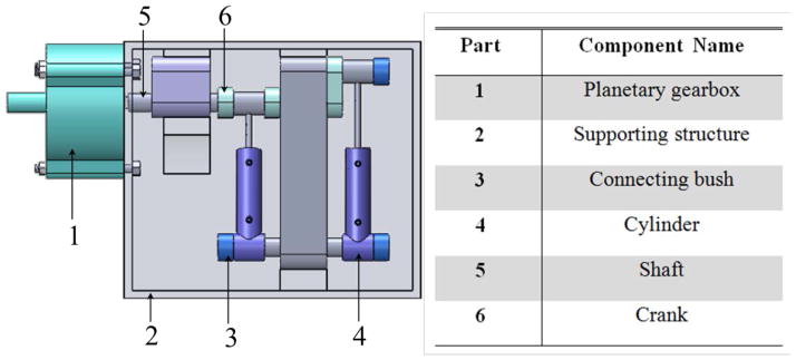
A 3-D assembly view of the stepper motor consisting of six major components, all of which are made of Acrylonitrile Butadiene Styrene (ABS), except for the connecting bush that is made of Nylon 101.
3.2 Working Principle
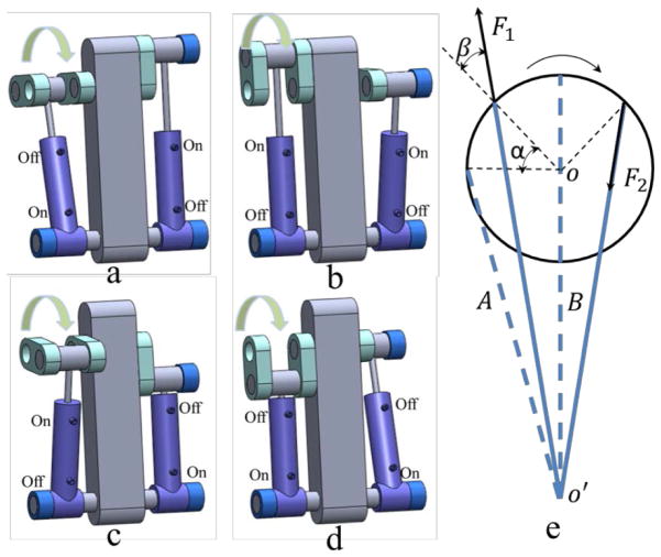
Two cylinders are coupled along a rotating axis, between which the pressure difference provides the elemental driving force of the mechanism. Each cylinder has two ports supplied with pressured air in different time phase. The pressure difference is induced when either one of the chambers is pumped with air. This generates movement of the piston towards the opposite side with the lower pressure, in turn providing a torque about the rotation center. As results, the actuation acts a pair of two stroke engines such that two pistons can extend and contract the strokes in constantly 90° phase difference. Note that the second cylinder attachment is offset circumferentially by 90° from the first cylinder. This ensures that whenever one cylinder is at a critical motive point, the other cylinder is at a point allowing for exerting an effective force to resume the rotation. Fig. 2 illustrates a complete sequential motion of the proposed stepper motor. The motor home position (Fig. 2a) is defined where its right cylinder is at the critical movement position. The left cylinder and the right one are, respectively, extended and contracted simultaneously, thus generating rotational movements about the rotating axis. This force drives the motor to rotate 90° as in Fig. 2b. Once both cylinders contract, it drives the motor to rotate another 90° (Fig. 2c). In the next phase of motion, the left cylinder keeps being contracted, whilst the right one is being extended; thereby causing the step motor reached to the position shown in Fig. 2d. Both cylinders will then extend to return the home position (Fig. 2a). The stepper motor operates in rotational resolution of 90° acting as a single step size, throughout the sequential motion. The gearbox is integrated to reduce such a step size into a desired angle. For example, the use of 25:1 gearbox minimizes the step to 3.6°.
Fig. 2.
(a–d): Pneumatic control sequence for yielding one rotation cycle in 360°. Each sequential step is actuated by the pressured air flow regulated by closing (off) and opening (on) the corresponding pneumatic valves. The reverse of the step sequence yields rotation the other way around. (e): Schematic diagram showing the force components F1 and F2 coupling along the axis (o) of rotation. The dashed blue line indicates the initial configurations of the two cylinders. After α-degree rotation, the current two configurations are indicated by the solid blue lines. The axis o′ denotes rotation axis of the cylinder base.
3.3 Theoretical Calculations
We hypothesize that dimensions of the cranks and cylinder are correlated to output torque of the stepper motor. Fig. 2e shows the motor operating schematic diagram from side view. F1 denotes the extension force of the left cylinder, and F2 is the contraction force of the right cylinder. Then the force provided by each cylinder (F1, F2) can be written as
| (1) |
where ΔP is the pressure difference of two cylinder chambers of each cylinder, and S is the effective area of the piston inside the cylinder which is considered as a constant value. The friction between the cylinder and chambers is neglected; hence, F1 and F2 are regarded as constant values during the operation as both the air pressure and piston area are maintained at constant level during the motor operation.
Without loss of generality, F1 and F2 can be normalized in unit of 1 N in order to simplify the calculation of the motor configuration. Let the radius of cylinder tip trajectory be r and the distance oo′ between the crank axis and the pivot point of the cylinder be l. The angle between F1 and the normal direction can be achieved based on the triangle side formula below:
| (2) |
Therefore, the output torque generated by cylinder A and B can be written as:
| (3) |
As a result, the output torque of the whole system is summarized by TA and TB:
| (4) |
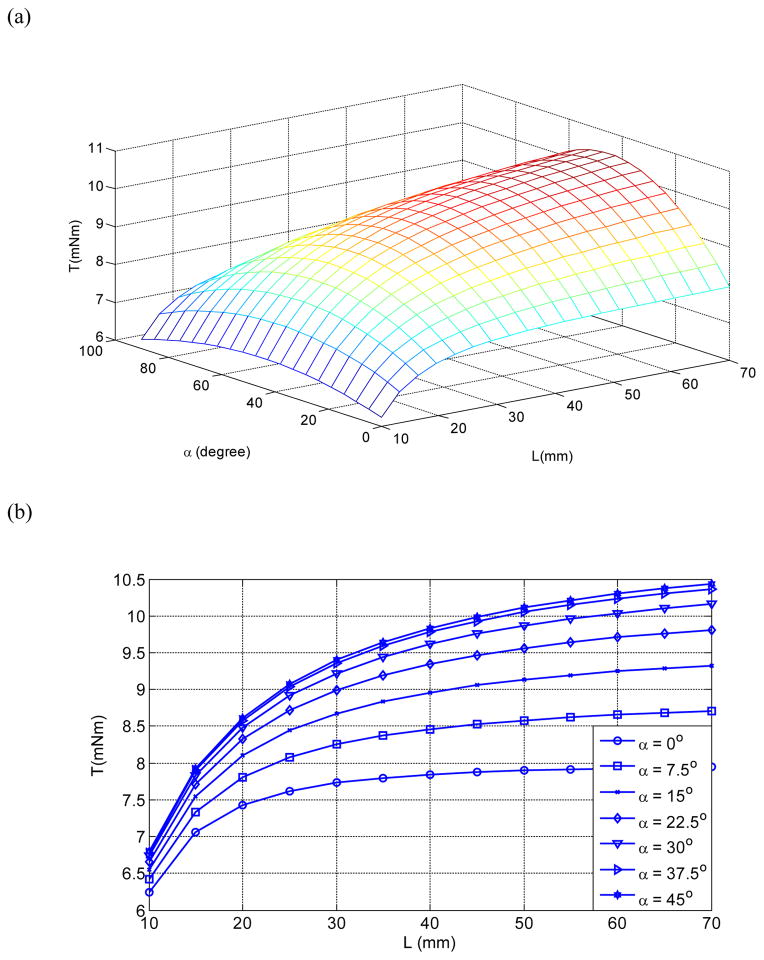
Referred to equations (1–4), the output torque is proportional to the pressure (T ∝ ΔP). Increasing air pressure difference between two cylinders is an alternative to achieve the higher output torque in some applications. It is worth noting that the range of α within a single step is always [0, 90°] in one working step. Provided with the mechanical constraint that r is always constant, the system output torque with respect to α and l can be obtained, of which the 2D function is depicted as in Fig 3.
Fig. 3.
(a) Output torque denoting a 2-D function varying by angular displacement α and separation l between two axes oo′ (Fig. 2); (b) Output torque with respect to separation l.
The output torque rises to its saturate level when the value of l increases further. Fig. 3b shows the growth of output torque is only significant in a smaller value of l, at any angular configuration, α. For instance, at α =45°, the output torque is about to reach its upper bound (10.5mNm) for l= 70mm. Effective increase of the torque can be found only within the length from 10mm to 40mm. It implies that system output torque will no longer improve obviously with an excessively long piston rod, but this will significantly increase the motor size in an unpractical way. The correlation between the output torque and the radius can be theoretically obtained in the similar way. The choice of motion radius is taken into consideration of two constraints: 1) r has to be smaller than l; 2) the dimension of the whole system has to be minimized. Optimal value of l is found to be 40mm and r is 8mm in our case.
4. Results
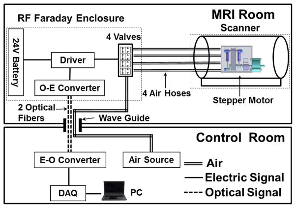
Fig. 4 illustrates an exemplary setup of MRI-guided intervention in the clinical environment, where the pneumatic actuation system is set up in and connected between the MRI room and control room. In the MRI room, the system comprises the proposed pneumatic stepper motor, four MR-conditional piezoelectric valves (PS11111-B, Hoerbiger, Germany), piezoelectric driver, a 24V battery power supply, and optical-electrical (O-E) converter (Fiber Optic Audio Link, CARL’S ELECTRONICS, USA), all of which are electromagnetically shielded in Radio Frequency (RF) faraday enclosure. In the control room, the control signal is transmitted via optical fibers from a data acquisition (DAQ) card (USB-6009, NI, USA) and a PC using an electrical-optical (E-O) converter. It is worth noting that the operation sequence of two ports in one cylinder has to be opposite; therefore, two sets of optical/fiber converters are adopted to control two corresponding cylinders. The pressured air is supplied via pneumatic hoses from a compressed air source which is placed outside of the MRI scanner room at a safe distance. The pressured air flow is regulated by the pneumatic valves, and conveyed through the four hoses connecting with the stepper motor.
Fig. 4.
An overview of the presented motor and its electronic driver in MRI scanner room and control room.
4.1 Motor Torque Characteristics
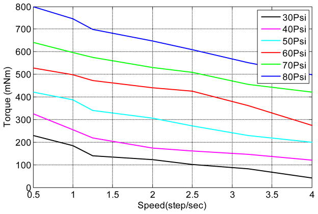
Output torque is one of the primary standards to evaluate the actuation performance of a stepper motor [23, 24], which also determines the overall dynamic response of a robotic structure. The output torque of our motor with respect to various levels of speed and input air pressure is investigated, as shown in Fig. 5. The maximum torque is approximately 800 mNm under mostly tolerated input air pressure at 80 Psi. The overall output torques are higher than that of the three stepper motors aforementioned, relative to the same air pressures. Similar to their motor characteristics, the decline of torque with increasing speed due to a low-pass filter effect [23] can be observed within the range of speed given. It is because the compressible air is driven into the hose with higher speed, thus causing the damping of the pressure waves inside the hose. This torque performance is comparable to PneuStep which was adopted in a robotic system to perform transperineal percutaneous needle access for prostate brachytherapy under MRI guidance, of which the maximum torque is about 650mNm with an input pressure of 120 Psi. Furthermore, our proposed motor operates with much stronger output torque of 230mNm, but at a normal air pressure of 30 Psi only. The allowable torque of our presented motor is larger than the commercial MR-conditional piezoelectric motor, Shinsei USR-30, with the maximum torque of 50mNm. As compared, our motor allows for higher flexibility in designing a robotic instrument through the adjustment of input air pressure, so as to fulfill various requirements for wider range of surgical applications.
Fig. 5.
Output torque varied with motor speed regulated by the operating frequency of the pneumatic valves. Six levels of air pressure were tested.
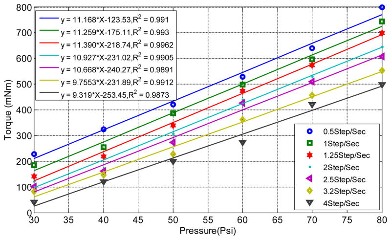
Fig. 6 shows the proportional correlation between output torque and input air pressure at seven levels of operating speed. The linear regression is applied to describe this correlation. It results in R-square values lightly ranging from 0.9873 to 0.9962. The resultant slopes of regression lines are estimated from 11.39 to 9.31. This coincides with the theoretical model denoted in equations (1–4) that the output torque is always proportional to input air pressure. Theoretical value of the constant gradient can be deduced and calculated as nearly ≈16. Such difference from this theoretical value is due to the energy power loss of any pneumatic driving approach, in which the energy transfer is mainly conducted by air movement from the pressured air source to the motor. We assume that the ideal and realistic output torque can be then expressed as:
| (6) |
where CI and CR are the y-intercept constants of their corresponding linear regressions at speed v=0.5 steps/s, and P1 denotes the air pressure supplied at time t1. Applying a certain amount of pressure change, the efficiency of power transfer from time t1 to t2 can be obtained as:
| (7) |
Fig. 6.
Output torque with respect to air pressure ranging from 30 to 80psi. Each linear regression applied to six sampling points in the experiment.
This experimental efficiency outperforms many sophisticated pneumatic actuators, their power efficiency can only be maintained around 20~30% in many cases [26, 27]. Simple design of our motor comprises small number of pneumatic components attributes the effective power transfer generally above 50%.
4.2 Motor accuracy analysis
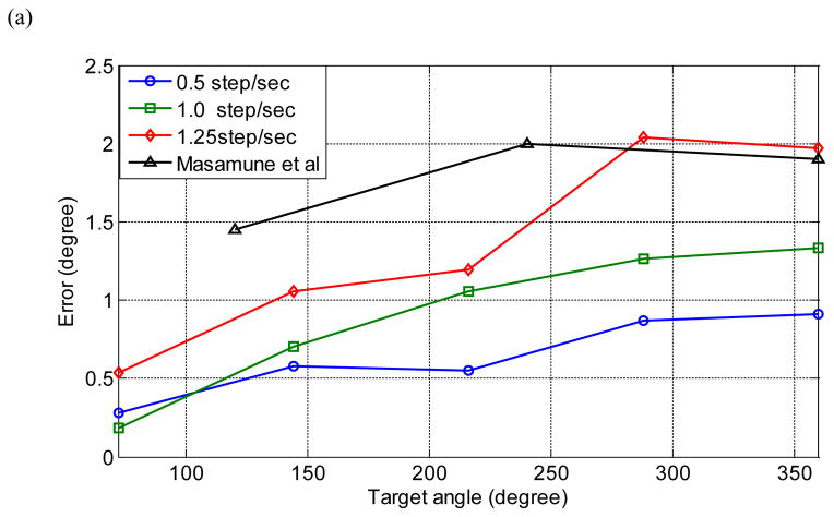
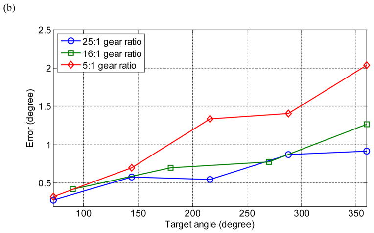
The motor accuracy was tested under different control specifications, namely, angular speed, gear ratio and target rotation angle, with constant air pressure (=30 psi) applied. To measure the accuracy of the stepper motor, the motor shaft was coupled with an optical encoder (E6B2-CWZ3E, OMRON, USA) that is capable of measuring rotation angle in the resolution of 0.35°. The experiment was performed by operating the stepper motor at different target angles from 72° to 360° with an increment of 72° per trial. Each data point in Fig. 7a–b is a mean of error values sampled by 5 times per trial in order to minimize the measurement error. Fig. 7a shows the correlation between the motor accuracy and the target angle. The motor operation speed measured in unit of steps per second is controlled by regulating operation frequency of the pneumatic valves. Three levels of operating speed are specifically selected for relatively slow and delicate robotic manipulation of needle insertion and catheterization. The motor was test repeatedly five times at the same condition; thereby, to find out the statistical significance, a two-way analysis of variance (ANOVA) [28] test is applied to all position errors obtained at different levels of speed and target angle. Both column and row p-values (<0.0002) far below a preset threshold level (=0.01). This demonstrates both the target angle and operating speed are the independent factors significantly yielding the rise of the angular displacement error. Furthermore, it is also observed that the accuracy of the presented motor is higher than that developed by Masamune et al. Fig. 7b shows the accuracy in the similar testing conditions, but the speed is altered with the use of three different gear ratios (25:1, 16:1, and 5:1). It is obvious that the larger gear ratio (the smaller step size), the smaller rotation error can be achieved. This error pattern is very similar to the pattern found in Fig. 7a of which the motor operation speed level is varied based on the operating pneumatic valve frequency. Both error patterns demonstrate an inverse relationship between the position error and the target angle; thereby, lower operating speed and larger gear ratio, both are the alternatives to guarantee the higher rotation accuracy.
Fig. 7.
(a) Angular errors with respect to target angles from 72° to 360°. Each data point represents the mean of five sampling values at the same testing condition. Error induced by the motor proposed by Masamune et al [24] is included for comparison; (b) Angular errors at three different gear ratios.
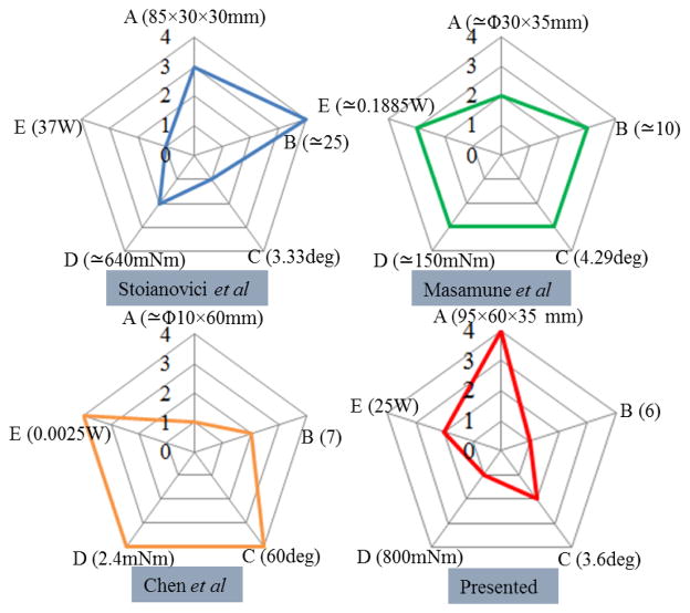
The comparative study of the motor physical parameters between our motor and the existing three motors is depicted in Fig. 8. Each stepper motor is ranked based on five evaluation standards. Our presented motor provides the largest torque, but also occupies the most volumetric size. The step size of our motor is similar to those developed by Stoianovici et al and Masamune et al; however, we demonstrate that our motor can flexibly adjust the step size with gearbox in different gear ratio in order to satisfy various operating requirements. The power of the presented motor is similar to that designed by Stoianovici et al, both of them far overweigh the other two motors. Only few components are involved in our design. The simplicity of working principle is considered as a very impressive characteristic for ease of the reliable implementation in many real practices.
Fig. 8.
Comparison among five evaluation standards. Note that rank 1 denotes the best in its corresponding standard. The smaller the size of pentagon, the better is the overall performance in terms of A: motor dimension, B: number of components, C: step size, D: motor output torque, E: power.
4.3 Compliance to MRI environment
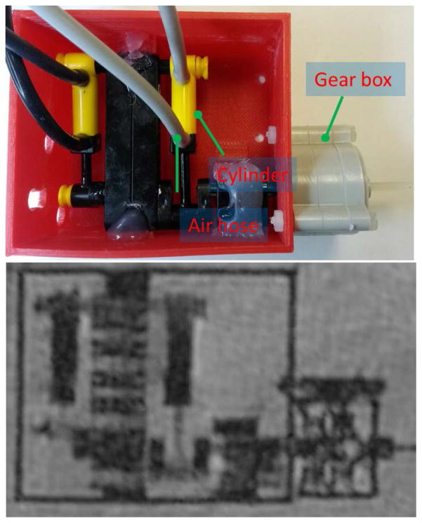
The compliance of the present motor to the MRI environment were quantified by measuring the SNR and the maximum width of image artifacts generated by the motor, if presented [29, 30]. The ASTM F2119 standard [31] was used to quantify the size of the image artifacts surrounding the presented motor. Image artifact is defined by 30% changes of the pixel intensity in the MR image before and after the introduction of the tested motor [31]. Fig. 9 shows the image artifact generated by the stepper motor and its 1:1 comparison to the motor object. No obvious image artifact can be observed apart from the motor components themselves.
Fig. 9.
Real image (top) showing the basic components of the stepper motor. The corresponding high-SNR MR image (bottom) without any observable artifacts.
In the SNR test, the motor was put in a container filled with CuSO4 solution and imaged at the isocenter of the scanner, where induced with the strongest magnetic field. The turbo spin echo (TSE) sequence was adopted to obtain the MR images The SNR value is calculated [16] as follows:
where Icenter is the mean of the intensity values within the 40×40 pixel region located at the image center, and SDcorner is the standard deviation of the intensity values within the 40×40 pixel region at the image corner. Fig. 10 shows the SNR generated by the stepper motor under three conditions, when the motor is: 1) not in the MR scanner; 2) is at rest but with electronics powered; 3) in motion. The first condition is selected as the control experiment, relative to which the moving motor causes the most reduction, but only ≈2.35% that is within an acceptable range [16].
Fig. 10.
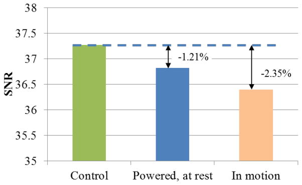
SNR of the stepper motor under 3 different conditions
5. Discussion
This paper presents a design of pneumatic stepper motor with the relatively simple working mechanism. The motor output torque performance, rotation accuracy and repeatability, pneumatic actuation parameters as well as its MRI compatibility were tested and investigated in detail. Compared to the current advanced pneumatic motors compatible with MRI [23–25], our simple-designed motor comprises far fewer numbers (=6) of components so that only a pair of two-stroke engines is required to generate the stepper movement, instead of using gear mechanism. The primary merit is that, in a reasonable size, the motor offers not just the large range of output torques (<800mNm), but also ensures high accuracy for robotic actuation. These act as important features for minimally invasive surgery (MIS).
The proposed motor was repeatedly operated at various target angles, with respect to several operating conditions: air pressure, gear ratio and pneumatic valve frequency, of which the optimal combination for higher accuracy was also investigated. With the design simplicity of this motor, the investigated performances are found to be consistent with the expected kinematic model deduced from its simple working principle. In terms of the image quality, we also prove that the proposed motor does not generate any observable artifact on the MR images, and it causes minimal SNR reduction during the motor operation under the MRI. All these merits demonstrate its high clinical potential for application in MR imaged-guided and robot-assisted MIS, for instance, needle biopsy and needle based drug delivery which are the common surgical approaches in prostate biopsy and brachytherapy [32]. Detailed assessment scheme has also been proposed which serves as a benchmark for the future design of MR-conditional pneumatic motor. To develop a high degree-of-freedom (DoF) robotic structure [33] for complicated surgical procedures, many motors will have to be integrated in a rather confined structural space; therefore, our ongoing work focuses on miniaturization of the motor design by exploiting advances of high-precision 3D printing, so that the motion accuracy will also be improved. In the future work, we will integrate these motors into a robotic instrument motorized with multiple DoFs. The overall performance will be evaluated under MRI by measuring the position of its instrument tip with the use of our MRI-conditional active tracking coil system [34].
Acknowledgments
This work was supported by National Institutes of Health (NIH) U41-RR019703, Dr. Richard J. Schlesinger Grant, and The Croucher Foundation Fellowship.
References
- 1.McRobbie DW, Moore EA, Graves MJ, Prince MR. MRI from Picture to Proton. Cambridge University Press; 2006. [Google Scholar]
- 2.Hetts S, Saeed M, Martin A, Evans L, Bernhardt A, Malba V, et al. Endovascular catheter for magnetic navigation under MR imaging guidance: Evaluation of safety in vivo at 1.5 T. American Journal of Neuroradiology. 2013;34:2083–2091. doi: 10.3174/ajnr.A3530. [DOI] [PMC free article] [PubMed] [Google Scholar]
- 3.Navkar NV, Deng Z, Shah DJ, Tsekos NV. A Framework for Integrating real-time MRI with Robot Control: Application to Simulated Transapical Cardiac Interventions. Biomedical Engineering, IEEE Transactions on. 2013;60:1023–1033. doi: 10.1109/TBME.2012.2230398. [DOI] [PubMed] [Google Scholar]
- 4.Chen Y, Ge J, Kwok KW, Nilsson KR, Fok M, Zion TT. MRI-conditional catheter sensor for contact force and temperature monitoring during cardiac electrophysiological procedures. Journal of Cardiovascular Magnetic Resonance. 2014;16:P150. [Google Scholar]
- 5.Kwok KW, Chen Y, Chau TC, Luk W, Nilsson KR, Schmidt EJ, et al. MRI-based visual and haptic catheter feedback: simulating a novel system’s contribution to efficient and safe MRI-guided cardiac electrophysiology procedures. Journal of Cardiovascular Magnetic Resonance. 2014;16:O50. [Google Scholar]
- 6.Liberman L, Bracero N, Morris E, Thornton C, Dershaw DD. MRI-guided 9-gauge vacuum-assisted breast biopsy: initial clinical experience. American Journal of Roentgenology. 2005;185:183–193. doi: 10.2214/ajr.185.1.01850183. [DOI] [PubMed] [Google Scholar]
- 7.Han BK, Schnall MD, Orel SG, Rosen M. Outcome of MRI-Guided Breast Biopsy. American Journal of Roentgenology. 2008 Dec;191:1798–1804. doi: 10.2214/AJR.07.2827. [DOI] [PubMed] [Google Scholar]
- 8.Hall WA, Truwit CL. Intraoperative MR - guided neurosurgery. Journal of Magnetic Resonance Imaging. 2008;27:368–375. doi: 10.1002/jmri.21273. [DOI] [PubMed] [Google Scholar]
- 9.McDannold N, Clement G, Black P, Jolesz F, Hynynen K. Transcranial MRI-guided focused ultrasound surgery of brain tumors: Initial findings in three patients. Neurosurgery. 2010;66:323. doi: 10.1227/01.NEU.0000360379.95800.2F. [DOI] [PMC free article] [PubMed] [Google Scholar]
- 10.Song SE, Hata N, Iordachita I, Fichtinger G, Tempany C, Tokuda J. A workspace - orientated needle - guiding robot for 3T MRI - guided transperineal prostate intervention: evaluation of in - bore workspace and MRI compatibility. The International Journal of Medical Robotics and Computer Assisted Surgery. 2012 doi: 10.1002/rcs.1430. [DOI] [PMC free article] [PubMed] [Google Scholar]
- 11.Fischer GS, Iordachita I, Csoma C, Tokuda J, DiMaio SP, Tempany CM, et al. MRI-compatible pneumatic robot for transperineal prostate needle placement. Mechatronics, IEEE/ASME Transactions on. 2008;13:295–305. doi: 10.1109/TMECH.2008.924044. [DOI] [PMC free article] [PubMed] [Google Scholar]
- 12.Pondman KM, Fütterer JJ, ten Haken B, Schultze Kool LJ, Witjes JA, Hambrock T, et al. MR-guided biopsy of the prostate: an overview of techniques and a systematic review. European urology. 2008;54:517–527. doi: 10.1016/j.eururo.2008.06.001. [DOI] [PubMed] [Google Scholar]
- 13.Gassert R, Yamamoto A, Chapuis D, Dovat L, Bleuler H, Burdet E. Actuation methods for applications in MR environments. Concepts in Magnetic Resonance Part B-Magnetic Resonance Engineering. 2006 Oct;29B:191–209. [Google Scholar]
- 14.Masamune K, Kobayashi E, Masutani Y, Suzuki M, Dohi T, Iseki H, et al. Development of an MRI-compatible needle insertion manipulator for stereotactic neurosurgery. Computer Aided Surgery. 1995;1:242–248. doi: 10.1002/(SICI)1522-712X(1995)1:4<242::AID-IGS7>3.0.CO;2-A. [DOI] [PubMed] [Google Scholar]
- 15.Vartholomeos P, Bergeles C, Qin L, Dupont PE. An MRI-powered and controlled actuator technology for tetherless robotic interventions. The International Journal of Robotics Research. 2013;32:1536–1552. [Google Scholar]
- 16.Chinzei K, Kikinis R, Jolesz FA. MR compatibility of mechatronic devices: Design criteria. Medical Image Computing and Computer-Assisted Intervention, Miccai’99, Proceedings. 1999 Jan;1679:1020–1030. [Google Scholar]
- 17.Briggs RW, Dy-Liacco I, Malcolm MP, Lee H, Peck KK, Gopinath KS, et al. A pneumatic vibrotactile stimulation device for fMRI. Magnetic Resonance in Medicine. 2004 Mar;51:640–643. doi: 10.1002/mrm.10732. [DOI] [PubMed] [Google Scholar]
- 18.Zappe AC, Maucher T, Meier K, Scheiber C. Evaluation of a pneumatically driven tactile stimulator device for vision substitution during fMRI studies. Magnetic Resonance in Medicine. 2004 Apr;51:828–834. doi: 10.1002/mrm.20021. [DOI] [PubMed] [Google Scholar]
- 19.Tse ZTH, Elhawary H, Rea M, Davies B, Young I, Lamperth M. Haptic Needle Unit for MR-Guided Biopsy and Its Control. Mechatronics, IEEE/ASME Transactions on. 2012 Feb;17:183–187. [Google Scholar]
- 20.Muntener M, Patriciu A, Petrisor D, Mazilu D, Bagga H, Kavoussi L, et al. Magnetic resonance imaging compatible robotic system for fully automated brachytherapy seed placement. Urology. 2006 Dec;68:1313–1317. doi: 10.1016/j.urology.2006.08.1089. [DOI] [PMC free article] [PubMed] [Google Scholar]
- 21.Bergeles C, Vartholomeos P, Qin L, Dupont PE. Closed-loop commutation control of an MRI-powered robot actuator. Robotics and Automation (ICRA), 2013 IEEE International Conference on; 2013. pp. 698–703. [Google Scholar]
- 22.Wang Y, Su H, Harrington K, Fischer G. Sliding mode control of piezoelectric valve regulated pneumatic actuator for MRI-compatible robotic intervention. ASME Dynamic Systems and Control Conference-DSCC; 2010. [Google Scholar]
- 23.Stoianovici D, Patriciu A, Petrisor D, Mazilu D, Kavoussi L. A new type of motor: Pneumatic step motor. Mechatronics, IEEE/ASME Transactions on. 2007 Feb;12:98–106. doi: 10.1109/TMECH.2006.886258. [DOI] [PMC free article] [PubMed] [Google Scholar]
- 24.Sajima H, Kamiuchi H, Kuwana K, Dohi T, Masamune K. MR-Safe Pneumatic Rotation Stepping Actuator. Journal of Robotics and Mechatronics. 2012 Jul;24:820–827. [Google Scholar]
- 25.Chen Y, Mershon CD, Tse ZTH. A 10-mm MR-Conditional Unidirectional Pneumatic Stepper Motor. Mechatronics, IEEE/ASME Transactions on. 2014:1–7. doi: 10.1109/TMECH.2014.2305839. [DOI] [PMC free article] [PubMed] [Google Scholar]
- 26.Cai M, Kawashima K, Kagawa T. Power assessment of flowing compressed air. Journal of fluids engineering. 2006;128:402–405. [Google Scholar]
- 27.Maolin C, KAGAWA T. Energy consumption assessment of pneumatic actuating systems including compressor. Proceeding of International Conference on Compressors and their Systems; 2001. pp. 381–390. [Google Scholar]
- 28.Hogg RV, Ledolter J. Engineering statistics. Vol. 358. MacMillan; New York: 1987. [Google Scholar]
- 29.Yu N, Gassert R, Riener R. Mutual interferences and design principles for mechatronic devices in magnetic resonance imaging. International journal of computer assisted radiology and surgery. 2011;6:473–488. doi: 10.1007/s11548-010-0528-2. [DOI] [PubMed] [Google Scholar]
- 30.Stoianovici D. Multi - imager compatible actuation principles in surgical robotics. The International Journal of Medical Robotics and Computer Assisted Surgery. 2005;1:86–100. doi: 10.1002/rcs.19. [DOI] [PMC free article] [PubMed] [Google Scholar]
- 31.ASTM. F2119 Standard Test Method for Evaluation of MR Image Artifacts from Passive Implants. 2013 Available: http://www.astm.org/Standards/F2119.htm.
- 32.Song S-E, Cho NB, Fischer G, Hata N, Tempany C, Fichtinger G, et al. Development of a pneumatic robot for MRI-guided transperineal prostate biopsy and brachytherapy: New approaches. Robotics and Automation (ICRA), 2010 IEEE International Conference on; 2010. pp. 2580–2585. [DOI] [PMC free article] [PubMed] [Google Scholar]
- 33.Kwok KW, Tsoi KH, Vitiello V, Clark J, Chow GC, Luk W, et al. Dimensionality reduction in controlling articulated snake robot for endoscopy under dynamic active constraints. Robotics, IEEE Transactions on. 2013;29:15–31. doi: 10.1109/TRO.2012.2226382. [DOI] [PMC free article] [PubMed] [Google Scholar]
- 34.Qin L, Schmidt EJ, Tse ZTH, Santos J, Hoge WS, Tempany-Afdhal C, et al. Prospective motion correction using tracking coils. Magnetic Resonance in Medicine. 2013;69:749–759. doi: 10.1002/mrm.24310. [DOI] [PMC free article] [PubMed] [Google Scholar]


