Abstract
Both endogenous and externally applied electrical stimulation can affect a wide range of cellular functions, including growth, migration, differentiation and division. Among those effects, the electrical field (EF)-directed cell migration, also known as electrotaxis, has received broad attention because it holds great potential in facilitating clinical wound healing. Electrotaxis experiment is conventionally conducted in centimetre-sized flow chambers built in Petri dishes. Despite the recent efforts to adapt microfluidics for electrotaxis studies, the current electrotaxis experimental setup is still cumbersome due to the needs of an external power supply and EF controlling/monitoring systems. There is also a lack of parallel experimental systems for high-throughput electrotaxis studies. In this paper, we present a first independently operable microfluidic platform for high-throughput electrotaxis studies, integrating all functional components for cell migration under EF stimulation (except microscopy) on a compact footprint (the same as a credit card), referred to as ElectroTaxis-on-a-Chip (ETC). Inspired by the R–2R resistor ladder topology in digital signal processing, we develop a systematic approach to design an infinitely expandable microfluidic generator of EF gradients for high-throughput and quantitative studies of EF-directed cell migration. Furthermore, a vacuum-assisted assembly method is utilized to allow direct and reversible attachment of our device to existing cell culture media on biological surfaces, which separates the cell culture and device preparation/fabrication steps. We have demonstrated that our ETC platform is capable of screening human cornea epithelial cell migration under the stimulation of an EF gradient spanning over three orders of magnitude. The screening results lead to the identification of the EF-sensitive range of that cell type, which can provide valuable guidance to the clinical application of EF-facilitated wound healing.
Introduction
It has been demonstrated that electrical field (EF) is able to affect a variety of cellular activities both in vitro and in vivo, including growth, migration, differentiation and division.1–5 For example, it has been observed that the physiological EF can enhance and direct embryonic development and neural regeneration.1,5,6 External EF stimulation can also be applied to induce alignment and coupling of myocardia and improve the performance of engineered heart tissues.7 Although not well understood, it has been proposed that EF could also act as a guidance cue to promote and direct cancer cell migration since metastatic cancer cells have shown active responses to the applied direct-current (DC) EF.8,9 Among these EF-induced effects, EF-directed cell migration, also known as electrotaxis, has received particular attention and has been studied extensively due to its potential applications in wound healing and regenerative medicine.10–13 EF-directed cell migration has been demonstrated for a variety of cell types. Interestingly, most of the cell types migrate towards cathodes with only a few towards anodes.14 It has been shown in in vitro experiments that both PI(3)Kγ and PTEN signalling pathways are activated during electrical stimulation, therefore EF could act as a primary directional cue for cell migration.2 Moreover, the electrotaxis principle has been extended to animal and clinical trials. For instance, the EF has been shown to facilitate the functional recovery of spinal cord injury in vivo.15–17 It has also been employed in treatments of various chronic wounds, including pressure, arterial and diabetic ulcers with positive results shown in clinical trials.18–20
Experimental investigation on electrotaxis has been conducted in centimetre-sized flow chambers built in Petri dishes.11 The experimental setup has several major limitations, including (i) low throughput (only one set of experimental conditions can be investigated at a time), (ii) poorly controlled microenvironment (a centimetre-sized test chamber and a two-probe stimulation method can lead to non-uniform EF distributions and therefore uneven cell migratory patterns), and (iii) reagent/sample consumption (the conventional electrotaxis setup requires cellular samples in millilitres to be fully dispersed into the electrical stimulation chamber, which could be challenging to obtain for certain rare cells (e.g., human stem cells)). Recent introduction of microfluidics has enabled high-throughput biological and biochemical investigations with minimal sample consumption and optimal system automation in a miniature package (from sub-millimetre to micrometre scales).21–23 Moreover, the highly controllable microenvironment in the microfluidic network could provide parallel and quantitative analyses of cellular activities on subcellular and even molecular levels, which cannot be achieved in its mesoscale counterparts.24–26 Recently, a few attempts have been made to adopt the microfluidic technology to cell migration studies. For instance, a microfluidic assay to stimulate the controlled wound healing has been reported, which allows serial studies of fibroblast migration at an engineered wound edge under various EF stimulation conditions.27 In another effort, chemical gradients have been implemented in a microfluidic device and compared with the EF in order to identify dominating cues in the directional migration of T cells in a combined stimulation environment.28 More recently, a microfluidic chip capable of generating multiple (up to four) EF levels has been developed, which enables multiple discrete-cell electrotaxis experiments to be conducted in parallel.27,29 Although the recent advances in applying the microfluidic approaches to electrotaxis research partially address certain technical hurdles mentioned above, they still require complicated external electrical control and power supply, as well as EF monitoring systems, which restricts further extension of the bioengineered platform to biological/clinical laboratories and point-of-care wound healing applications. Furthermore, there is a lack of a systematic design strategy for optimal high-throughput experiments over a wider range of EF stimulation.
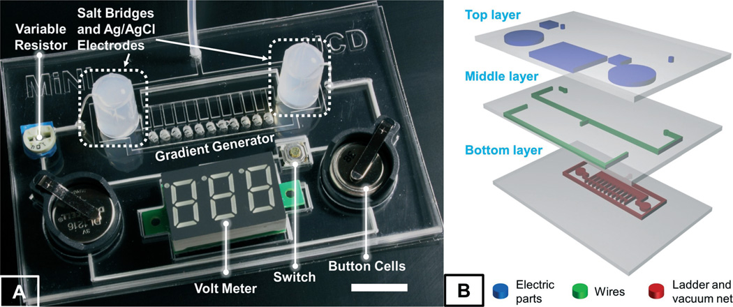
In this paper, we present a miniature independently operable microfluidic platform for high-throughput quantitative electrotaxis studies, referred to as ElectroTaxis-on-a-Chip (ETC). As compared to all of the existing devices, our ETC device is the first fully integrated microfluidic system that includes all the necessary functional components for cell migration under EF stimulation (except a microscope). More importantly, utilizing the R–2R resistor ladder theory in digital signal processing (DSP), we have developed a systematic approach to design an infinitely expandable microfluidic generator of EF gradients for high-throughput and quantitative electrotaxis studies, which cannot be accomplished by any existing technology to the best of our knowledge. This is of particular importance as different cells exhibit various levels of sensitivity and biological responses to the stimulating EF, and a high-throughput quantitative electrotaxis screening with a wide range of EF gradients can help to quantitatively characterize and determine cellular sensitivity (i.e. the EF threshold to activate cellular responses), which provides both valuable insights into the fundamental understanding of the electrotaxis phenomenon and quantitative design guidance for clinical applications.30,31 In addition, screening over an extensive EF range could help to establish an effective safety boundary for clinical EF stimulations, as cellular responses to EF exhibit nonlinear characteristics and high-strength EF stimulation may impose adverse effects on cells.32,33 As illustrated in Fig. 1A, the prototype device consists of (i) Ag/AgCl stimulating electrodes to minimize the impact of interfacial electrochemical reactions on living cells and to reduce the overall input voltage due to its non-polarizable properties, (ii) lithium battery cells to provide miniaturized and high-voltage power supply, (iii) an electricity regulator (i.e., an on-chip variable resistor) to allow easy adjustment of EF in the electrotaxis chamber, and (iv) a miniature LED voltmeter (activated by an on-chip switch) for continuous EF monitoring inside the electrotaxis chamber. More importantly, by integrating all functional components on the chip, the overall ETC platform can fit into a footprint same as the size of a credit card, which can be easily adopted to any biological and clinical research environment. It is worth noting that a vacuum-assisted assembly method has been utilized to allow direct and reversible attachment of our device to existing cell culture media on biological surfaces, which could completely separate the cell culture and device preparation/fabrication and thus significantly improve the success rate of the experiments. To demonstrate the applicability of our ETC platform, we have investigated the EF dependence of the electrotaxis of human corneal epithelial cells (hTCEpi) and identified a non-linear response with a maximal directedness (0.959 ± 0.007) at the field strength of 101.2 mV mm−1. In brief, combining all of the desirable bioengineered features, our ETC platform provides an integrated, quantitative, high-throughput screening solution to increasingly use electrotaxis analyses in both fundamental research and clinical applications.
Fig. 1.
(A) An image of the integrated ETC device (bar is 1 cm) and (B) a 3D illustration showing the three-layer structure of the ETC device.
Operation principles of the EF gradient generator
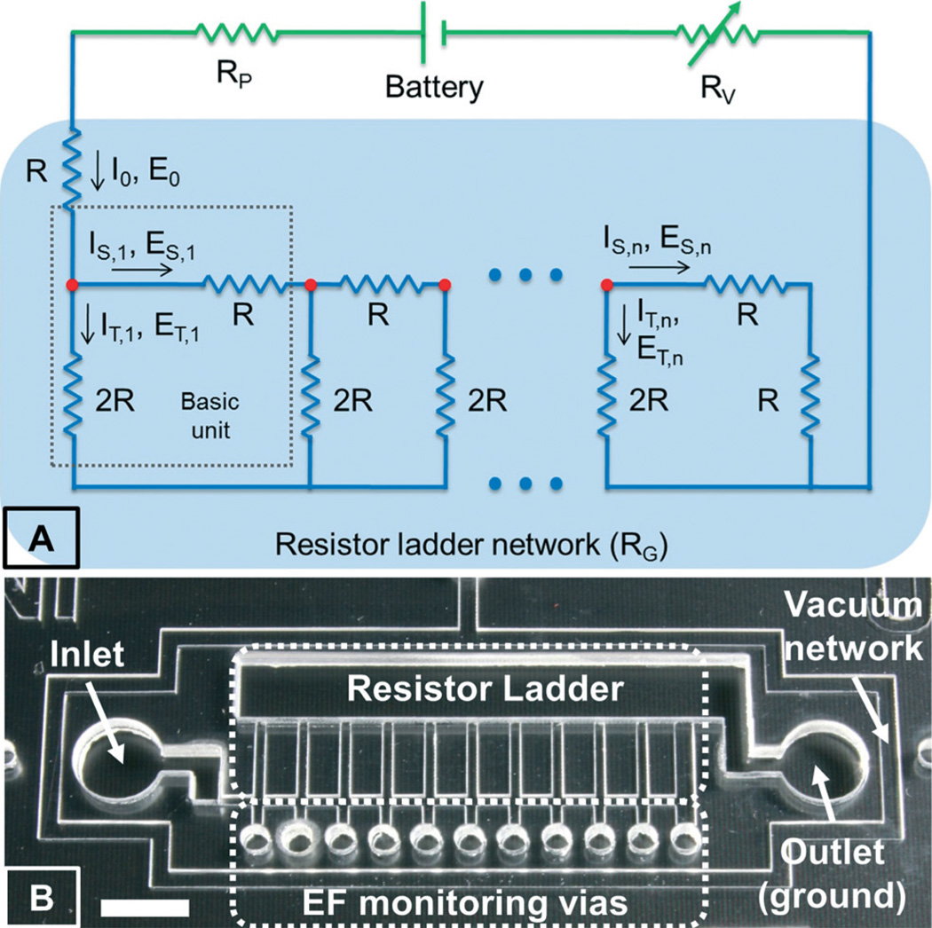
As a key feature of our ETC platform, the design of the infinitely expandable EF gradient generator is inspired by the R–2R resistor ladder structure because of its modular expandable design, easy scalability, and constant power consumption. Specifically, the resistor ladder structure consists of repeating identical units of current dividers, each of which uses one series resistor of R and one shunt resistor of 2R, as shown in Fig. 2A. The shunt resistor at the last unit is set to be R in order to terminate the sequence. As the input current reaches the first unit, it experiences an equal split (at the red dot) between the series (IS) and the shunting (IT) paths due to the impedance matching between these two paths, and thus only half of the input current flows down to the next stage. This process repeats itself at each serial connecting unit, providing a simple way to establish logarithmic series of EF gradients with a common ratio of 2. The reported device, as shown in Fig. 1A and 2B, includes 11 units, which generates EF gradients ranging over 3 orders of magnitude (i.e., 1024 = 2(11-1)). Interestingly, this simple modular design can be easily scalable to any number of units or gradient levels. Moreover, the R–2R resistor ladder structure has constant input impedance, independent of the size of the network. As a consequence, the constant input impedance and the modular design have made the R–2R resistor networks infinitely expandable without increasing total power consumption. More importantly, it allows simple implementation in microfluidic networks due to the fact that only two standard resistor values (R and 2R) are repetitively used and the inherent simplicity of the design, that is, the EF gradient is solely dependent on the ratio of the two resistors rather than their actual values. In our ETC platform, the microfluidic resistors are constituted by microchannels filled with conductive electrolyte solutions (e.g. cell culture medium). The electrical resistance can be easily adjusted by changing the microchannel dimensions, following Ohm's law. To simplify the design rule and standardize the fabrication process, we only alter the channel lengths in order to achieve the desired electrical resistance while keeping the channel width and height constant, similar to the design of resistors in semiconductor devices. In summary, this innovative R–2R microfluidic network topology combines the advanced network theory with simple microfluidic implementation to enable simultaneous generation of a wide range of quantitative EF gradients for on-chip high-throughput electrotaxis stimulation.
Fig. 2.
(A) An electrical equivalent circuit model of our ETC device and (B) a zoomed-in view of the EF gradient generator using the R–2R resistor ladder network; bar is 5 mm.
Materials and methods
Materials
Sylgard 184 silicone elastomer (polydimethylsiloxane (PDMS)) was purchased from Dow Corning. The FNC coating mix (an aqueous solution of fibronectin and other cell adhesion proteins) was purchased from Athena Environmental Sciences. Silicone connection tubing was purchased from A–M Systems. Steinberg's solution was prepared using a previously published recipe.11 Agar was purchased from Sigma. The 1 ml plastic pipette tip used to make the salt bridge was bought from USA Scientific. Metal wires with insulating coating for electrical connection, lithium button cells, button cell holders and the variable resistors were bought from a local RadioShack store. Silver wires with 99.999% purity were purchased from Advent Research Materials Ltd. The mini voltmeter was obtained from Adafruit Industries. The switch was bought from Mouser Electronics.
Cell culture
Telomerase-immortalized human corneal epithelial cells (hTCEpi) were obtained from Dr. Jim Jester (UC Irvine), Dr. Vijay Krishna Raghunathan and Dr. Christopher J. Murphy (UC Davis).34 hTCEpi cells were routinely cultured in the EpiLife® medium supplemented with an EpiLife defined growth supplement (EDGS, Life Technologies, Grand Island, USA) and 1% (v/v) penicillin/streptomycin (Life Technologies). Cells were incubated at 37 °C with 5% CO2 until they reach ~70% confluence and were used between passages 40 and 70 for all electrotaxis experiments.
Device design and fabrication
As shown in Fig. 1B, our ETC device is composed of three PDMS layers. The bottom layer consists of the EF gradient generator for stimulated cell migration and a vacuum network surrounding the gradient generator for reversible assembly of the device on a pre-cultured cell layer on a biological surface. The top and middle layers contain recess features that hold the batteries, a variable resistor, a voltmeter and a switch. The electrical connecting wires are also embedded in the middle layer. A series of small circular holes are cut through all three layers for monitoring the EF in the gradient generator (Fig. 2B). Two reservoirs are placed over the inlet and outlet (ground) of the gradient generator for EF application (Fig. 2B).
The three-layer PDMS structure can be fabricated and assembled by employing standard laser micromachining and oxygen plasma-assisted bonding. In brief, PDMS prepolymer at a mixing ratio of 10 : 1 was thoroughly mixed and degassed in a desiccator for 20 minutes. One PDMS slab with a thickness of 400 µm and two slabs with a thickness of 1.5 mm were prepared using the moulding method with spacers to control the layer thickness. The bottom layer was fabricated in the 400 µm thick PDMS, while the middle and top layers were fabricated in the 1.5 mm thick PDMS using a cutthrough mode of a CO2 laser cutter (VLS 2.30). After thorough cleaning of the PDMS pieces in an ethanol ultrasonic bath, the bottom and middle layers were permanently bonded together following an oxygen plasma treatment at 90 W for 20 seconds. The connecting electrical wires (255 µm in diameter), made from insulated stainless steel threads, were then embedded into the corresponding channels in the middle layer. In the subsequent step, the top layer was aligned and bonded to the middle layer using the same plasma treatment procedure. The voltmeter, battery holders, switch, variable resistor and two salt bridges with 2% agar in Steinberg's solution were fixed into the matched recesses in the top layer. The silver wires were coated with silver chloride by passing a current of 50 mA for 1 minute in physiological saline before inserting into the salt bridges. They were used as stimulating electrodes in our electrotaxis experiments. Finally, a vacuum tube connected to an adjustable vacuum pump was inserted into the through-hole vacuum access to provide reversible device packaging to interface with the cell culture. Since the fabrication of our ETC device only requires well-established laser micromachining and plasma-assisted bonding methods and the attachment of the ETC device to the cell culture Petri dish is simply achieved by vacuum force, the success rate for the preparation of the ETC device is close to 100%.
Sealing characterization of the vacuum-assembled device
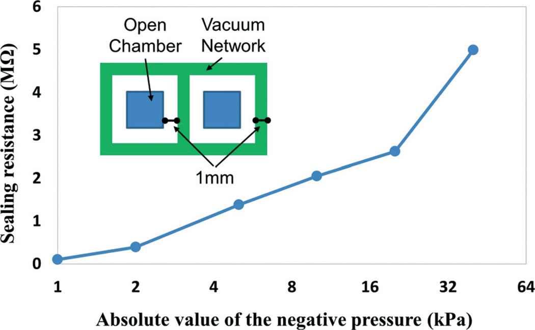
The electrical sealing is essentially important for our ETC device, which ensures minimal current leakage into the surrounding medium and the correct function of the EF gradient generator. A series of sealing tests have been conducted to find the minimal vacuum sealing pressure for cell-device integration. As shown in the Fig. 3 inset, the testing device consists of two open-surface chambers separated by a vacuum network. The separation distance between the open chambers and the vacuum channel and the width of the vacuum channel are designed to be 1 mm in order to match with the resistive ladder network. The electrical sealing in terms of sealing resistance between the two independent chambers is characterized by using a multimeter equipped with Ag/AgCl electrodes at various vacuum-sealing pressures, ranging from 1 kPa to 40 kPa.
Fig. 3.
Sealing resistance at different vacuum levels with an inset showing the design of the testing device.
Electrotaxis experiment and time-lapse image recording
Prior to the electrotaxis experiments, the cells were harvested from the culture flask at a density of 5 × 10⁴ cells per milliliter. The 100 mm cell culture dish was coated with a FNC Coating Mix, following the manufacture's instruction to facilitate cell attachment. The cells were cultured in the dish for 1 hour in a 37 °C 95% air/5% CO2 incubator to allow sufficient attachment. The ETC device was thoroughly cleaned with 70% ethanol in DI water and exposed to UV radiation prior to the electrotaxis experiment. The ETC device was vacuum-assembled on the cell culture substrate. Extra cell culture medium (~1 ml) was added into the inlet and outlet reservoirs to ensure good salt bridge contact and support cell viability during EF stimulation. The cells in the EF gradient channels did not show any signs of apoptosis, damage, detachment and changes of motility during EF stimulation.
During the electrotaxis experiment, EF strengths were monitored at the beginning of the experiment and every 30 minutes afterward to ensure consistent EF application. An inverted microscope (Carl Zeiss, Oberkochen, Germany) equipped with a motorized stage and time-lapse imaging software (Metamorph NX; Molecular Devices, Sunnyvale, USA) was used to capture the cell migration videos. The microscope system was able to record videos of multiple locations on the ETC chip simultaneously. Therefore, all EF conditions in the gradient generator could be monitored and tested in one single experiment. A regular 10× objective lens was used for microscopy. To maintain cell viability during imaging, a Carl Zeiss incubation system was used.
Quantification of cell migration
Time-lapse images of cell migration were analysed by using ImageJ software from the National Institutes of Health (http://rsbweb.nih.gov/ij/). All adherent cells in the images were tracked at 5 minute frame intervals. The position of a cell was defined by its centroids. For each EF level, over 80 cells were analyzed. Cells that divided, moved in and out of the field, or merged with other cells during the experiment were excluded from analysis. The cell migration in our EF gradient generator was characterized using our previously published methods.35 Briefly, the directedness was used as an indicator of directionality of cellular migration, which is defined as the cosine of the angle between the EF vector and the net cellular translocation direction. A cell migrating directly toward the cathode would have a directedness of +1. For a group of cells, an average directedness close to 0 represents random migration. Circular statistics was also employed to analyse our experimental results using a free MATLAB toolbox (CircStat).36 In this method, the cell migration directions were plotted in angular histograms. The mean resultant vector could be calculated from the migration data, of which the angle indicated the average migration direction, while the length (from 0 to 1) indicated the circular spread of the migration directions around the average (a length close to 1 means that the individual cell migration directions were concentrated around the average). Moreover, the cell migration rate was quantified as the track speed which was presented as the accumulated migration distance per hour.
Data were expressed as mean ± standard error of the mean (SEM). Statistical analysis was performed using SPSS software with unpaired two-tailed Student's t-test, and p was set at 0.05 for rejecting null hypotheses.
Results and discussion
Vacuum-assisted cell-device integration
Integrated cell culture can be extremely challenging in conventional microfluidic devices, where the coating of extracellular matrix proteins and the loading of cellular samples are difficult steps, although enclosed microfluidic platforms offer many advantages over conventional assays.37 In this paper, we try to avoid any inconvenience of microfluidic cellular injection and culture by implementing a reversible vacuum-assisted assembly. It allows the cells to be cultured first in a conventional setup (e.g. Petri dish) under optimized conditions. The ETC device only needs to be reversibly attached to the cell culture substrate through an activated vacuum-sealing network right before the electrotaxis experiment. This on-demand cell-device integration ensures that the cells are cultured and migrate under an optimal microenvironment. While conducting the device attachment, particular cautions should be taken to avoid scratching off cells from the cultured substrates. Air bubbles should also be prevented from being trapped inside the channels, which could inevitably lead to a change of impedance in microfluidic resistors and thus an unexpected gradient profile. To alleviate trapping and generation of gas bubbles, hydrophilic priming of the PDMS microfluidic channels becomes necessary by employing oxygen plasma treatment. Furthermore, the sealing performance has been quantitatively tested. As shown in Fig. 3, it indicates that a −10 kPa vacuum-sealing pressure provides a sealing resistance of more than 100 times higher than the resistance of the ladder network (18.83 kΩ, calculated by using the dimensions of the ladder and the conductivity of the cell culture medium, 1.73 S m−1), which is considered to be a sufficient electrical seal for the EF gradient stimulation. During the electrotaxis experiment, the cells present in the EF-stimulating channels have not been found dead or apparently affected in their migration patterns by the vacuum network.
Control of EF in the stimulation chamber
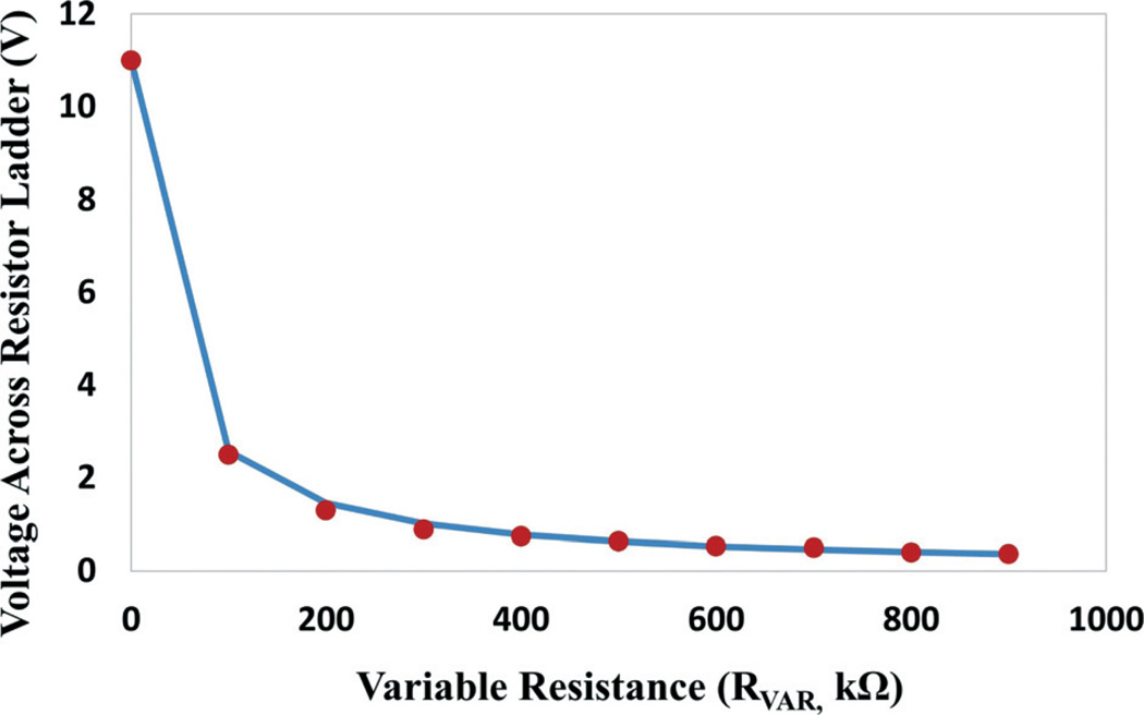
Our integrated ETC platform provides convenient on-chip control over the strength of the EF stimulation in the gradient-generating chambers by using a variable resistor (RV). In order to determine the range of the variable resistor, each electrical component in the equivalent circuit in Fig. 2A has been experimentally assessed to achieve a reasonable approximation of the circuit. It has been found that the resistance of gradient generators (RG) contributes significantly to the overall resistance and is measured at 18.64 kΩ, close to the theoretical prediction mentioned in the previous section, while the peripheral circuit resistance (RP, including the Ag/AgCl electrode, the salt bridge and the wires) is on the same order of magnitude (assessed at 11.86 kΩ). Accordingly, the voltage drop across the gradient ladder (VG) can be expressed using eqn (1), where VP is the battery voltage. The EF in the first level of the gradient ladder (E0, in Fig. 2A) can be calculated using eqn (2), where L is the length of the series resistor channel. The first-level EF (E0) establishes the upper boundary of the gradient, from which the field strength of the following levels can be derived using the common ratio (2) of the gradient. A variety of variable resistors have been tested in our platform. Among those tested, a variable resistor with a resistance range of 0–1 MΩ provides a wide range of adjustment in the voltage drop (VG) across the gradient-generating ladder structure from 0.36 V to 11 V under a power supply (VP) of 18 V (Fig. 4). It corresponds to an EF gradient of 0.1 mV mm−1 to 72 mV mm−1 at the high-resistance side and 2.7 mV mm−1 to 2.2 V mm−1 at the low-resistance end, which is sufficient for our biological investigation. In the high-throughput electrotaxis screening experiments, the variable resistor is adjusted to establish an EF gradient from 2.1 mV mm−1 to 1.6 V mm−1, covering the entire EF-sensitive range of the human cornea epithelial cells.
| (1) |
| (2) |
Fig. 4.
Voltage across the resistor ladder network at different values of the variable resistor under a power supply of 18 V. The line is the theoretical calculation using eqn (1) and the dots are measurement results.
Infinite electrical field gradient generator
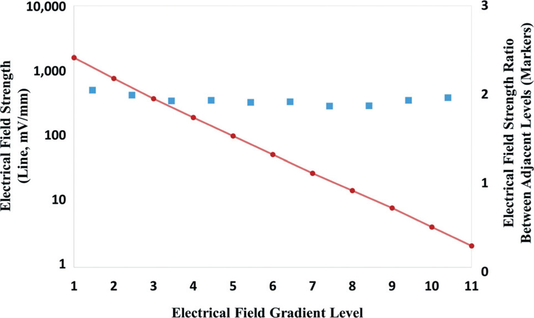
We have designed and fabricated an 11-level EF gradient generator with a common ratio of 2, as shown in Fig. 2B. The microchannels are 0.5 mm in width and 400 µm in height. The series resistor channels are 2.5 mm in length, while the shunt resistor channels are 5 mm in length. The last shunt resistor channel is 1 mm in width to terminate the gradient series. A voltage of 18 V supplied by six button battery cells (3 V each) is used to power the entire circuitry, including the LED voltmeter display, with the variable resistor adjusted for an optimized EF gradient range from 2.1 mV mm−1 to 1.6 V mm−1. The EF gradient can be conveniently measured using circular voltage monitoring through vias, as shown in Fig. 2B, and the on-chip LED voltmeter equipped with Ag/AgCl electrodes. The voltmeter is activated by the switch only during the voltage measurement in order to minimize power consumption. In case the voltage is below the precision of the on-chip voltmeter, a hand-held multimeter can be used to measure the EF. Fig. 5 summarizes the experimental measurement results in each chamber. As can be seen, the EF gradients follow a highly logarithmic relationship. In the meantime, the EF strengths between two adjacent chambers keep a consistent ratio of 2, which is in excellent agreement with our theoretical predication.
Fig. 5.
The EF strength measured in our 11-level gradient generator (line) and the ratio between adjacent levels (square markers).
The ETC device does not affect basal cell motility
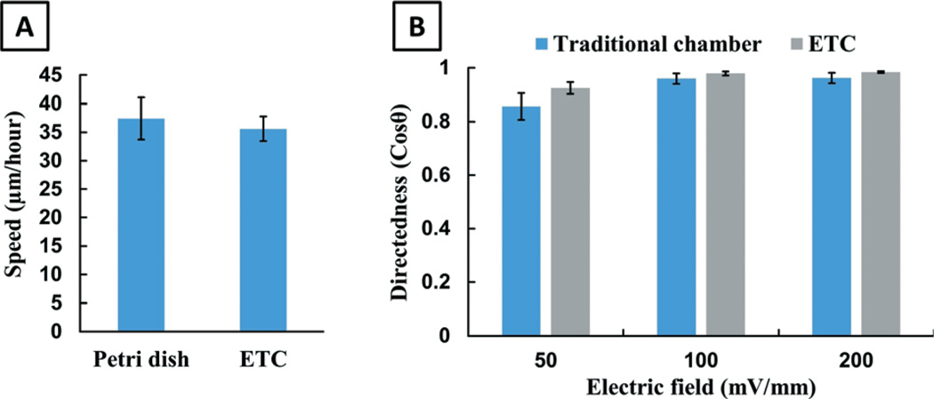
Cell motility can be affected by many environmental factors. Our ETC device provides cells with a highly confined environment, which is different from the conventional electrotaxis experimental setup. Therefore, we first want to determine whether cells would move differently in our ETC chip without EF stimulation (basal cell motility). Briefly, the cells are seeded in a Petri dish or the ETC device for 1 hour. Subsequently, the migration of cells is recorded by time-lapse microscopy in a period of 2 hours. It is found that the cells seeded in the ETC device spread in the same manner as those plated on the Petri dish. There is also no observable difference in cellular morphology between these two experimental groups. After spreading, most cells polarize spontaneously and show random migration, with no significant difference in mean speed between the two experimental groups, as shown in Fig. 6A (p = 0.51). From the experimental results, we conclude that the basal cell motility is not influenced by the ETC chip.
Fig. 6.
(A) The microfluidic chip does not affect basal cell motility and (B) the ETC device shows robust electrotaxis.
The ETC device shows EF-directed cell migration the same as the traditional electrotaxis chamber
We then evaluate EF-stimulated cell migration in the ETC device under three different voltages (50, 100 and 200 mV mm−1) and compare it with the experiments conducted in a traditional electrotaxis chamber. As shown in Fig. 6B, hTCEpi cells show directional migration in the ETC device under all experimental conditions with the same directedness values as those of conventional experiments (p > 0.20).
High-throughput electrotaxis screening of human corneal epithelial cells
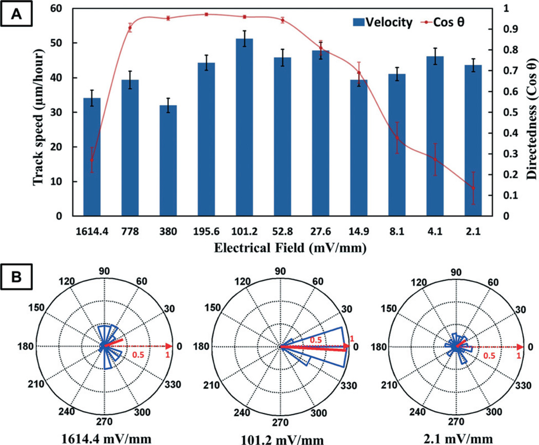
As aforementioned, it is necessary to determine the EF sensitivity of cells/tissues as well as the safe and effective range of EF for the clinical applications of EF stimulation. Our ETC device is able to simultaneously generate wide-range EF gradients in an integrated and miniaturized setup, which is ideal for high-throughput electrotaxis screening. In this work, we aim to study the directional migration of human corneal epithelial cells (hTCEpi cells) under EF stimulation of different strengths. ETC devices with an 11-level resistor ladder generating EF gradients from 2.1 mV mm−1 to 1.6 V mm−1 are utilized. The experimental results show that the directional migration of hTCEpi cells is EF strength-dependent (Fig. 7 and the ESI† videos). Cells move in random directions when exposed to weak EF stimulations of 2.1 mV mm−1 and 4.1 mV mm−1, with directedness values of 0.135 ± 0.077 and 0.273 ± 0.077, respectively. As the EF strength increases above 8.1 mV mm−1, cells start to show obvious morphological changes and gradually increased cathodal migration. After the EF reaches 52.8 mV mm−1, the cells become strongly oriented perpendicularly to the EF vector and form a broad lamellipodium facing the cathode. At 101.2 mV mm−1, hTCEpi cells migrate toward the cathode with the highest directedness of 0.959 ± 0.007, which is about a 6-fold increase compared to the directedness at 2.1 mV mm−1. Most of the cells begin to retract membrane extensions from the anodefacing side shortly after we apply EF (5 minutes), and extend lamellipodia toward the cathode. After electrical stimulation at 101.2 mV mm−1 for 2 hours, 100% of cells migrate towards the cathode and about 80% of the cells migrate with a Euclidean distance of more than 50 µm. In contrast, among the cells stimulated by 2.1 mV mm−1 EF, only 60% migrate towards the cathode and 44% migrate more than 50 µm. When EF strength increases to 1614.4 mV mm−1, cells start elongating and migrating perpendicularly to the EF vector. The migration distance also decreases. Some cells even detach from the substrate due to the high-strength EF stimulation. However, the track speed analysis does not show that the EF strength correlates with the migration velocity of hTCEpi cells. These findings are of great importance to the identification of the effective EF strength for clinical corneal wound treatment. Moreover, our ETC device can be directly adopted for the high-throughput electrotaxis screening of other types of cells and wounds, which could potentially lead to improved therapies for the chronic or clinically difficult wounds. In addition, the screening results indicate the threshold strength of effective EF stimulation, which could help to minimize the adverse effects of clinical electrical treatment.
Fig. 7.
(A) The track speed and directedness of cell migration under EF stimulation of different strengths. (B) Circular statistics is also shown for the cell migration at 1614.4 mV mm−1, 101.2 mV mm−1 and 2.1 mV mm−1. The mean resultant vectors (solid red lines) in the circular statistics charts indicate the average direction and the circular spread of the cell migration.
Conclusion
In this paper, we present a novel ElectroTaxis-on-a-Chip (ETC) platform that integrates all functional components (including electrodes, power, control and monitor units) of an electrotaxis experiment into one independently operable device with a very compact footprint (the same as a credit card). It enables the electrotaxis investigations to be conducted in a low-cost, high-throughput, high-efficiency, quantitative fashion in a generic biological research setting. In such implementation, we have incorporated an infinitely expandable microfluidic generator of EF gradients for high-throughput parallel screening of EF-directed cell migration, which is designed based on the R–2R resistor ladder topology in digital signal processing. Noticeably, a vacuum-assisted packaging method has been utilized to allow direct reversible application of the ETC device to existing cell culture media, which could completely separate the live cell culture and device preparation/fabrication and thus significantly improve the success rate of the biological experiments. To demonstrate its applicability, the EF-directed migration of human corneal epithelial cells has been studied. The high-throughput experimental results illustrate that our ETC platform can be utilized to efficiently study cellular response to EF with an extended EF range and could provide quantitative guidance to select an effective and safe EF simulation range for animal and clinical studies.
Supplementary Material
Acknowledgements
This work is supported in part by the National Science Foundation, the CAREER Award (ECCS-0846502) to Dr. Tingrui Pan, the National Institutes of Health National Eye Institute grant (1R01EY019101) to Dr. Min Zhao and the Major Program Grant of Zhejiang Provincial Science and Technology (No. 2012C03007-6) to Dr. Zhengping Xu. Kan Zhu is supported by a fellowship from the China Scholarship Council. The authors would like to thank Dr. Jim Jester, Dr. Vijay Krishna Raghunathan and Dr. Christopher J. Murphy for supplying the human corneal epithelial cells.
Footnotes
Electronic supplementary information (ESI) available: Cell migration video in the 11-level EF gradient generator. See DOI: 10.1039/c4lc00745j
Contributor Information
Min Zhao, Email: minzhao@ucdavis.edu.
Tingrui Pan, Email: tingrui@ucdavis.edu.
Notes and references
- 1.McCaig CD, Rajnicek AM, Song B, Zhao M. Physiol. Rev. 2005;85:943–978. doi: 10.1152/physrev.00020.2004. [DOI] [PubMed] [Google Scholar]
- 2.Zhao M, Song B, Pu J, Wada T, Reid B, Tai G, Wang F, Guo A, Walczysko P, Gu Y, Sasaki T, Suzuki A, Forrester JV, Bourne HR, Devreotes PN, McCaig CD, Penninger JM. Nature. 2006;442:457–460. doi: 10.1038/nature04925. [DOI] [PubMed] [Google Scholar]
- 3.Borgens RB, Blight AR, Mcginnis ME. Science. 1987;238:366–369. doi: 10.1126/science.3659920. [DOI] [PubMed] [Google Scholar]
- 4.Borgens RB, Roederer E, Cohen MJ. Science. 1981;213:611–617. doi: 10.1126/science.7256258. [DOI] [PubMed] [Google Scholar]
- 5.Nuccitelli R. Radiat. Prot. Dosim. 2003;106:375–383. doi: 10.1093/oxfordjournals.rpd.a006375. [DOI] [PubMed] [Google Scholar]
- 6.Song B, Zhao M, Forrester J, McCaig C. J. Cell Sci. 2004;117:4681–4690. doi: 10.1242/jcs.01341. [DOI] [PubMed] [Google Scholar]
- 7.Radisic M, Park H, Shing H, Consi T, Schoen FJ, Langer R, Freed LE, Vunjak-Novakovic G. Proc. Natl. Acad. Sci. U. S. A. 2004;101:18129–18134. doi: 10.1073/pnas.0407817101. [DOI] [PMC free article] [PubMed] [Google Scholar]
- 8.Mycielska ME, Djamgoz MBA. J. Cell Sci. 2004;117:1631–1639. doi: 10.1242/jcs.01125. [DOI] [PubMed] [Google Scholar]
- 9.Djamgoz MBA, Mycielska M, Madeja Z, Fraser SP, Korohoda W. J. Cell Sci. 2001;114:2697–2705. doi: 10.1242/jcs.114.14.2697. [DOI] [PubMed] [Google Scholar]
- 10.Tai GP, Reid B, Cao L, Zhao M. Chemotaxis. 2009;571:77–97. doi: 10.1007/978-1-60761-198-1_5. [DOI] [PubMed] [Google Scholar]
- 11.Song B, Gu Y, Pu J, Reid B, Zhao Z, Zhao M. Nat. Protoc. 2007;2:1479–1489. doi: 10.1038/nprot.2007.205. [DOI] [PubMed] [Google Scholar]
- 12.Nishimura KY, Isseroff RR, Nuccitelli R. J. Cell Sci. 1996;109:199–207. doi: 10.1242/jcs.109.1.199. [DOI] [PubMed] [Google Scholar]
- 13.Nuccitelli R. Curr. Top. Dev. Biol. 2003;58:1–26. doi: 10.1016/s0070-2153(03)58001-2. [DOI] [PubMed] [Google Scholar]
- 14.Li J, Lin F. Trends Cell Biol. 2011;21:489–497. doi: 10.1016/j.tcb.2011.05.002. [DOI] [PubMed] [Google Scholar]
- 15.Borgens RB, Toombs JP, Breur G, Widmer WR, Waters D, Harbath AM, March P, Adams LG. J. Neurotrauma. 1999;16:639–657. doi: 10.1089/neu.1999.16.639. [DOI] [PubMed] [Google Scholar]
- 16.Shapiro S, Borgens R, Pascuzzi R, Roos K, Groff M, Purvines S, Ben Rodgers R, Hagy S, Nelson P. J. Neurosurg. Spine. 2005;2:3–10. doi: 10.3171/spi.2005.2.1.0003. [DOI] [PubMed] [Google Scholar]
- 17.Borgens RB, Blight AR, Mcginnis ME. J. Comp. Neurol. 1990;296:634–653. doi: 10.1002/cne.902960409. [DOI] [PubMed] [Google Scholar]
- 18.Baker LL, Chambers R, DeMuth SK, Villar F. Diabetes Care. 1997;20:405–412. doi: 10.2337/diacare.20.3.405. [DOI] [PubMed] [Google Scholar]
- 19.Gardner SE, Frantz RA, Schmidt FL. Wound Repair Regen. 1999;7:495–503. doi: 10.1046/j.1524-475x.1999.00495.x. [DOI] [PubMed] [Google Scholar]
- 20.Isseroff RR, Dahle SE. Adv. Wound Care. 2012;1:238–243. doi: 10.1089/wound.2011.0351. [DOI] [PMC free article] [PubMed] [Google Scholar]
- 21.Whitesides GM. Nature. 2006;442:368–373. doi: 10.1038/nature05058. [DOI] [PubMed] [Google Scholar]
- 22.Unger MA, Chou HP, Thorsen T, Scherer A, Quake SR. Science. 2000;288:113–116. doi: 10.1126/science.288.5463.113. [DOI] [PubMed] [Google Scholar]
- 23.Thorsen T, Maerkl SJ, Quake SR. Science. 2002;298:580–584. doi: 10.1126/science.1076996. [DOI] [PubMed] [Google Scholar]
- 24.Takayama S, Ostuni E, LeDuc P, Naruse K, Ingber DE, Whitesides GM. Nature. 2001;411:1016–1016. doi: 10.1038/35082637. [DOI] [PubMed] [Google Scholar]
- 25.El-Ali J, Sorger PK, Jensen KF. Nature. 2006;442:403–411. doi: 10.1038/nature05063. [DOI] [PubMed] [Google Scholar]
- 26.Zare RN, Kim S. Annu. Rev. Biomed. Eng. 2010;12:187–201. doi: 10.1146/annurev-bioeng-070909-105238. [DOI] [PubMed] [Google Scholar]
- 27.Sun YS, Peng SW, Cheng JY. Biomicrofluidics. 2012:6. doi: 10.1063/1.4750486. [DOI] [PMC free article] [PubMed] [Google Scholar]
- 28.Li J, Zhu L, Zhang M, Lin F. Biomicrofluidics. 2012;6 doi: 10.1063/1.4718721. [DOI] [PMC free article] [PubMed] [Google Scholar]
- 29.Huang CW, Cheng JY, Yen MH, Young TH. Biosens. Bioelectron. 2009;24:3510–3516. doi: 10.1016/j.bios.2009.05.001. [DOI] [PubMed] [Google Scholar]
- 30.McCaig CD, Zhao M. BioEssays. 1997;19:819–826. doi: 10.1002/bies.950190912. [DOI] [PubMed] [Google Scholar]
- 31.Wang E, Zhao M, Forrester JV, McCaig CD. Exp. Eye Res. 2003;76:29–37. doi: 10.1016/s0014-4835(02)00257-9. [DOI] [PubMed] [Google Scholar]
- 32.Zhao Z, Watt C, Karystinou A, Roelofs AJ, McCaig CD, Gibson IR, De Bari C. Eur. Cells Mater. 2011;22:344–358. doi: 10.22203/ecm.v022a26. [DOI] [PubMed] [Google Scholar]
- 33.Feng JF, Liu J, Zhang XZ, Zhang L, Jiang JY, Nolta J, Zhao M. Stem Cells. 2012;30:349–355. doi: 10.1002/stem.779. [DOI] [PMC free article] [PubMed] [Google Scholar]
- 34.Robertson DM, Li L, Fisher S, Pearce VP, Shay JW, Wright WE, Cavanagh HD, Jester JV. Invest. Ophthalmol. Visual Sci. 2005;46:470–478. doi: 10.1167/iovs.04-0528. [DOI] [PubMed] [Google Scholar]
- 35.Cao L, Wei D, Reid B, Zhao S, Pu J, Pan T, Yamoah EN, Zhao M. EMBO Rep. 2013;14:184–190. doi: 10.1038/embor.2012.215. [DOI] [PMC free article] [PubMed] [Google Scholar]
- 36.Berens P. J. Stat. Softw. 2009;31:1–21. [Google Scholar]
- 37.Mehling M, Tay S. Curr. Opin. Biotechnol. 2014;25:95–102. doi: 10.1016/j.copbio.2013.10.005. [DOI] [PubMed] [Google Scholar]
Associated Data
This section collects any data citations, data availability statements, or supplementary materials included in this article.


