Abstract
This paper describes an approach to actuate magnetically arrays of microtissue constructs for long-term mechanical conditioning and subsequent biomechanical measurements. Each construct consists of cell/matrix material self-assembled around a pair of flexible poly(dimethylsiloxane) (PDMS) pillars. The deflection of the pillars reports the tissues’ contractility. Magnetic stretching of individual microtissues via magnetic microspheres mounted on the cantilevers has been used to elucidate the tissues’ elastic modulus and response to varying mechanical boundary conditions. This paper describes the fabrication of arrays of micromagnetic structures that can transduce an externally applied uniform magnetic field to actuate simultaneously multiple microtissues. These structures are fabricated on silicon-nitride coated Si wafers and contain electrodeposited Ni bars. Through-etched holes provide optical and culture media access when the devices are mounted on the PDMS microtissue scaffold devices. Both static and AC forces (up to 20 μN on each microtissue) at physiological frequencies are readily generated in external fields of 40 mT. Operation of the magnetic arrays was demonstrated via measurements of elastic modulus and dynamic stiffening in response to AC actuation of fibroblast populated collagen microtissues.
1. Introduction
Studying the organizational structure, mechanical behavior, and biological function of engineered tissue holds great promise for the future of artificial tissue and organ repair.1, 2 Static and dynamic mechanical conditioning during the engineering process has been found to enhance tissue structure, mechanical strength, and overall functionality.3–5 Conventional ways of mechanically conditioning engineered tissue involve the use of centimeter scale tissue samples and potentially complex bioreactor systems.6–9 These methods, however, are resource intensive, and the size of the tissues limits the diffusion of pharmacological treatments and the ability to image through the sample.
Recently, a range of microengineered devices fabricated from soft materials such as poly(dimethylsiloxane) (PDMS) have been developed that can measure the force generation (contractility) of millimeter or sub-mm-scale model tissues.10, 11 In these devices, cells and extracellular matrix (ECM) self-assemble under the contractile action of the cells into tissue constructs suspended between a pair of flexible vertical cantilevers. The resulting deflection of the cantilevers reports the net contractile force generated by the tissue. These microtissue strain gauges have enabled the study of contractility in a range of model tissues involving fibroblasts,10, 12 airway smooth muscle cells13 and cardiomyocytes.11, 14
The capability of such devices can be greatly expanded by enabling mechanical actuation of the cantilevers. We have recently developed an approach that enables mechanical stimulation of microtissues via magnetic actuation of magnetic microspheres bonded to the cantilevers of arrays of microtissue strain gauges (μTUGs).15–17 These magnetic microtissue tester (MMT) devices notably allow measurement of the mechanical stiffness of such constructs and have enabled analysis of the relative contribution of cells and matrix to relevant mechanical properties.15 The role of boundary conditions and mechanical constraints on tissue formation have also been investigated.17 These results have demonstrated the potential of magnetically driven microtissue constructs, but to date they have been achieved via serial actuation of individual microtissues with an electromagnetic tweezer device.18 This approach suffers from low throughput and does not enable long-term mechanical conditioning of microtissue arrays, e.g. during maturation. Thus, to date, the full potential of the MMT array devices has not been realized.
Here we describe an approach whereby simultaneous magnetically-driven mechanical actuation of an array of microtissues can be achieved. The essential concept is illustrated in Fig. 1. Microwells, each containing a pair of flexible pillars, are fabricated in a PDMS substrate,10 and a magnetic Ni microsphere is bonded to one of the pillars in each well.15, 16 A mixture of cells and ECM is introduced into the wells and, as the cells contract the mixture, they form an aligned microtissue spanning the pillars. The pillars bend due to the collective contractile force of the microtissue, providing a read-out of this force.10, 15 A small (~1 mm) Ni bar microfabricated on a Si wafer is placed near the magnetic pillar. When the sphere and bar are magnetized by an externally applied magnetic field BExt, the sphere is attracted to the bar with a magnetic force FMag, which controllably stretches the microtissue. The deflection of the non-magnetic pillar from the FMag = 0 state provides readout of the applied force. Figure 1(b) illustrates the realization of this approach in an array format. Multiple Ni bars align with the individual microtissues and holes etched through the Si wafer enable optical access and good exchange of culture media for the microtissues. We term this device a “lid array.” In this paper, we describe the fabrication and characterization of such Ni bar arrays, and illustrate their performance via both quasi-static and dynamic actuation of fibroblast-populated collagen microtissues. We find that the lid arrays achieve comparable accuracy in the determination of individual microtissue’s mechanical properties to that of the magnetic tweezer-based approach,15 but with the notable advantage of simultaneous actuation of multiple constructs in a non-contact mode. This preserves the sterility of the culture environment, and hence gives the potential for long-term stimulation protocols.
Fig. 1.
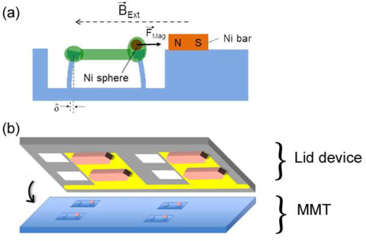
(a) Schematic of magnetic microtissue actuation system, showing a microtissue (green) whose tension deflects flexible micropillars. Application of a magnetic field BExt magnetizes the 100 μm diameter Ni sphere mounted on one of the micropillars, and also a nearby small Ni bar, creating a force between the sphere and the bar, FMag, which stretches the microtissue. The deflection δ of the left pillar reports the tissue’s force. (b) Schematic of a Si wafer “lid” device, showing Au fingers that serve as electrodes for electrodeposition of Ni bars (tan shapes) and holes (white squares) etched through the wafer that allow optical and media access to the microtissues. Alignment with the microtissue array is as indicated.
2 Materials and Methods
2.1 Lid Array Fabrication
In overview, the lid device consists of a through-etched silicon nitride-coated Si wafer with patterned gold fingers. Nickel bars are created on top of the gold circuitry via electrodeposition in order to transduce an externally applied uniform magnetic field into a local inhomogeneous field near each MMT. The construction of the lid device can be broken down into three segments: gold circuitry definition, nickel electrodeposition, and wafer through-etching. The component steps in the latter two processes were interleaved to ensure survivability of the features on the substrate.
The fabrication process is outlined in Fig. 2. First, patterned finger-shaped metal (Cr(7 nm)/Au(45 nm)) arrays 1,600 μm wide were fabricated on double-side-polished Si3N4-coated wafers using standard photolithography, thermal evaporation, and lift-off processing techniques (Fig. 2(a)). The position and size of the metal fingers were designed to align along the short edge of each individual microwell and fit to the empty space between two adjacent microwells. A 120 μm thick layer of SU-8 photoresist was then spun over the Au fingers, and patterns in the shape of the desired Ni bars were defined in this resist layer on the Au fingers (Fig. 2(b)). To ensure clean Au surfaces for the subsequent Ni electrodeposition, the top side of the substrate was RIE etched in O2 for 5 minutes to remove any remaining SU-8 on the exposed Au regions. Next, to define a mask for the wafer through-etching, an array of rectangular holes, each of dimension 1200 μm × 840 μm, was patterned in the Si3N4 on the reverse side of the Si wafer via backside alignment using standard photolithography and reactive ion etching in CF4 and O2 (Fig. 2(c)).19
Fig. 2.
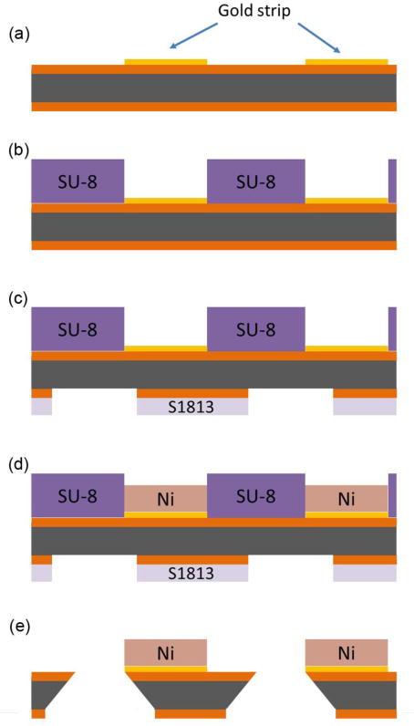
Side view of lid fabrication process flow. (a) Chrome/gold arrays were patterned onto double-side polished Si3N4 wafers using standard lithography techniques. The Si is shown in gray and the Si3N4 in orange (vertical dimensions not to scale). (b) SU-8 photoresist was patterned to define the shapes of electrodeposited Ni bars. (c) S1813 photoresist was patterned on the bottom of the wafer using back-side alignment, and the exposed silicon nitride was removed by reactive ion etching in CF4 to define a mask for wafer through-etching (d) Nickel bars were electrodeposited into the patterns established by the SU-8. (e) The wafer was etched in 30% w/v KOH at 130 C to create rectangular holes. Any remaining photoresist was removed by the KOH etch.
The Ni bars were then electrodeposited onto the previously defined patterns (Fig. 2(d)) to thicknesses of 50–100 μm, as desired, using the Au finger array as a working electrode. The nickel deposition solution consisted of 80.5 g nickel (II) sulfamate, 6.25 g nickel chloride, 10 g boric acid, and 0.05 g sodium dodecyl sulfate (SDS), in 250 mL water. For deposition, a potentiostat (Model 263A, Princeton Applied Research) was used in galvanostatic mode and was set to −1 V relative to a platinum reference electrode. The Ni bars included tips on both ends in order to accommodate substrate geometries wherein one nickel bar actuates two adjacent microtissues. In these experiments, the nickel bar only actuated one microtissue each.
Finally, the Si wafers were etched in a 30% w/v KOH solution at 150 °C for approximately 6 hours (Fig. 2(e)),19 to obtain through-holes that match the dimensions of the wells on the MMTs on the side of the wafers with the Ni bars. The KOH bath had the added effect of removing any remaining photoresist adhered to the wafer.
2.2 Lid Array Characterization
The lateral dimensions of the features on the lid devices were verified by optical microscopy. The thickness and uniformity of the Ni bars was measured by optical profilometry (VK-VX100, Keyence). The magnetic properties of the Ni bars were determined by removing individual Ni bars from the Si wafers and measuring them in a vibrating sample magnetometer (VSM) (DMS Model 10; ADE Technologies, Westwood, MA).
2.3 MMT Device Fabrication and Microtissue Formation
The PDMS MMT devices were fabricated via replica molding from PDMS molds, as described previously.10 They consisted of pairs of flexible pillars with separation 500 μm in wells with dimensions 800 μm × 400 μm × 170 μm deep. The PDMS had elastic modulus E = 1.6 MPa, and the pillars had length 115 μm and cross section 140 μm × 35 μm in their flexible sections, giving them an effective spring constant of k = 0.9 μN/μm for small deflections. Spherical Ni particles (Alfa Aesar #44739) with ~ 100 μm diameter were manually selected for roundness. After coating with liquid PDMS, a sphere was placed on one pillar in each well. The substrate was then baked overnight at 60C to allow the PDMS to dry and bond the spheres to the pillars. This bonding was robust, and in our experiments, we saw no detachment of the spheres from the pillars.
To form the microtissues, suspensions of NIH 3T3 fibroblasts and 2.5 mg/ml unpolymerized rat tail type-I collagen (BD Biosciences) were introduced into the wells as previously described.10, 15 The cells were cultured on the MMT devices for two days prior to measurements in high glucose Dulbecco’s Modified Eagle’s Medium (DMEM), supplemented with 10% bovine serum, 100 units/ml penicillin, and 100 μg/ml streptomycin (all from Invitrogen).
2.4 Magnetic Actuation
For both characterization measurements and probing of microtissues the lid arrays were mounted and aligned under a microscope on MMT devices. The arrays were actuated with a microscope-mounted dual-coil programmable electromagnet capable of producing magnetic fields of up to 50 mT with a uniformity of 3% over the largest arrays studied. To benchmark the lid devices’ performance, actuation of individual microtissues was also carried out using an electromagnetic tweezer device as described previously.15
Images of individual MMTs and microtissues were obtained using phase contrast microscopy with a 10× objective on a Nikon TE-2000E inverted microscope. For mechanical measurements of individual microtissues a quasi-static stretching protocol was used,15 during which images were recorded with a CoolSnap HQ (Photometrics) camera. To characterize sinusoidal actuation, movies were recorded at 100 frames/sec using a Prosilica GX-1050 camera (Allied Vision Technologies). The pillar deflections were determined from the images using ImageJ (NIH) for the quasi-static measurements and via custom tracking software written in IgorPro (WaveMetrics) for the dynamic actuation studies.
The stress, strain, and elastic modulus of each microtissue was determined from the quasi-static stretching data.15 Briefly, the force on each microtissue was found by tracking the deflection of the non-magnetic MMT pillar and calculating a force based on its spring constant. The stress in the central region of each microtissue was then obtained from the measured dimensions of the microtissue. The strain was measured locally in the microtissues’ centers from sequential phase contrast images, using a texture correlation analysis algorithm.20 The elastic modulus was determined from the slope of the resulting stress-strain curves.
3 Results
3.1 Fabrication and Geometrical Characterization
To test the fabrication and measurement procedures for the lid devices, we made arrays containing up to 20 electrodeposited Ni bars and corresponding through-holes on segments of silicon-nitride coated Si wafers. Figure 3(a) shows a portion of one such array. In this flash photograph the Ni bars, which are dark gray in ordinary light, appear light tan. The holes etched through the Si wafer with KOH appear as gray rectangles to the left of the Ni bars, and the Au strip used as a working electrode is visible against the black background of the Si wafer. The Ni bars were fabricated with pointed ends to concentrate magnetic flux and create larger field gradients in the neighborhood of the magnetic pillars. The bars shown have length 1.60 mm, width 450 μm, and tip width 90 μm. A range of smaller bars were also fabricated, but were found to generate insufficient magnetic force. To achieve alignment with our MMT arrays, the Ni bars were laid out on a rectangular grid with center-to-center spacing of 3.20 mm along the bars’ long axis and 1,20 mm along the short axis.
Fig. 3.
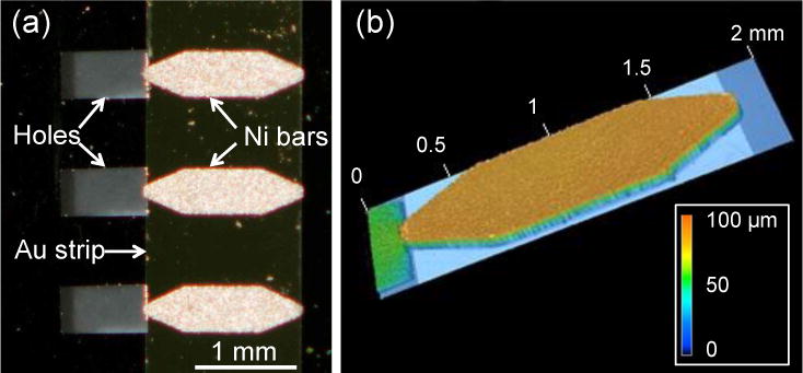
(a) Optical micrograph of a section of a lid array, showing three Ni bars, their underlying Au strip, and corresponding through-holes. The Ni bars appear bright due to reflected light from camera flash. The vertical-running edges of the Au strip are clearly seen, and the Si surface appears black. The holes appear gray due to the background below the wafer. (b) Height profile of a Ni bar, as indicated by the color scale. The thickness variation across the bar is < ± 2 μm. The bars’ dimensions were length L1 = 1.60 mm, width W1 = 450 μm, length of central rectangular section L2 = 775 μm, and tip width W2 = 90 μm. The region of the hole to the left of the bar appears in green due to an anomalous response of the optical profilometer to a region of that depth.
The dimensions of the Ni bars were characterized via optical profilometry. Figure 3(b) shows data for one such bar. We found that the overall lateral dimensions of the electrodeposited bars varied by < 0.6% along the long axis, and < 2% along the short axis. The tip widths varied by ~10%. Individual bars were quite flat, with height variations of less than 2%, as shown in Fig. 3(b). However, we found ~10% variation in the bars’ thicknesses t = 60 ± 7 μm (N = 27), likely from variations in the deposition current across the arrays. The KOH etching procedure gave ~5% variability in the dimensions of the holes in the Si wafers. However, this is not a critical parameter; for the purposes of this study the holes merely needed to be larger than the underlying MMT micro-wells to provide optical access through the Si wafer.
3.2 Magnetic characterization and modeling
Figure 4(a) shows the magnetic moment μBar vs. applied magnetic field for a representative Ni bar removed from the array and measured via VSM. As shown in Fig. 4(a), the magnetic hysteresis of the bars is small, with a remanent moment approximately 10% of the bars’ saturation moment μSat. Note that the measured value of μSat = 17.2 μAm2 agrees very well with that expected for the design dimensions and the room temperature saturation magnetization of Ni.21 The magnetic properties of the Ni spheres mounted on the pillars have been reported previously.16 Figures 5(a) and 5(b) show the deflection of a magnetic pillar due to the force produced by the Ni bar on the lid in an applied external magnetic field BExt = 40 mT. To assess the variability of the force generation, we measured a set of MMTs on an array and found deflections of 17.4 ± 2.5 μm (FMag = 15.7 ± 2.3 μN) in a field BExt = 34 mT (N = 9). Figures 4(b) and 4(c) show a finite-element modeling computation in the vicinity of one end of a Ni bar of the component Bx of the magnetic field parallel to a bar’s long axis in an external field of 34 mT, using the COMSOL Multiphysics package. Hysteresis effects were not included. From this we may estimate the force on a Ni bead on an adjacent MMT pillar as FMag = ∇ (μSph(B)•B), where μSph is the field-dependent magnetic moment of the Ni sphere in the total field B = BExt + BBar.16 At a bar-sphere spacing of 150 μm, the calculation shown in Figs. 4(b) and 4(c) yields B = 51.1 mT and dBx/dx = 180 T/m. At this field, the Ni spheres have μSph = 0.075 μA m2,16 which yields FMag ~ 14 μN, in reasonably good agreement with our measured value. Varying the bar thickness and tip width in the COMSOL computations by ±10% as per the measurements given in Section 3.1 showed variations in FMag of ≤ 15%, again in agreement with the measured variation of FMag.
Fig. 4.
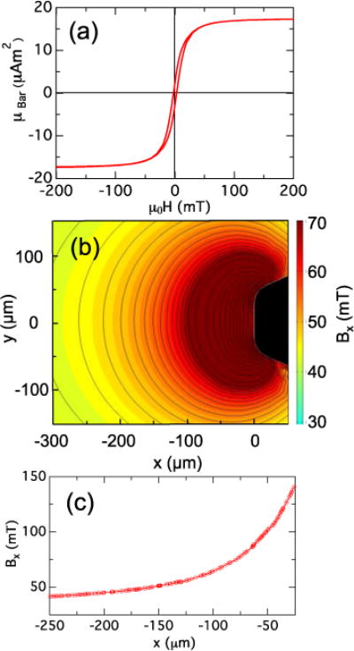
(a) Magnetic moment μBar of a Ni bar measured with a VSM. (b) Color contour map of computed field component Bx near end of a Ni bar with dimensions as given in the Caption of Fig. 3 (shown in black) in an external uniform field BExt = 34 mT directed along the x axis. For Bx ≤ 65 mT, the black contour lines have spacing 2 mT; for Bx ≥ 65 mT the spacing is 10 mT. (c) Bx vs x along the line y = 0 in panel (b).
Fig. 5.
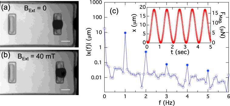
(a) MMT viewed through a lid device. The Ni sphere appears as a dark circle on the right-hand pillar. The tip of the Ni bar is visible at right. (b) Application of BExt = 40 mT deflects the magnetic pillar 30 μm to the right. Scale bars in (a) and (b) are 100 μm. (c) Inset: Motion of a magnetic pillar in response to a sinusoidal driving field BExt = B0 sin(2πft), with B0 = 20 mT and f = 0.5 Hz. Frequency doubling produces a 1 Hz response, as discussed in the text. Right hand scale shows FMag as determined from the pillar spring constant k = 0.9 μN/μm. (c) Main panel: Fourier spectrum of motion shown in inset (calculated over 10 periods). Harmonics of 1 Hz fundamental are shown as solid points.
To determine the suitability of the device for AC stimulation, we measured the response of the magnetic pillars to sinusoidal external fields. An example of a magnetic pillar’s motion in response to a 0.5 Hz AC magnetic field of amplitude 20 mT is shown in the inset to Fig. 5(c). Since FMag = ∇ (μSph(B)•B), the force and displacement are approximately quadratic in BExt, as we have shown previously when driving such MMT devices with a magnetic tweezer.15, 16 This leads to a frequency doubling for a sinusoidal driving field, and so the motion of the pillar is at 1 Hz. This motion is nearly sinusoidal with minimal distortion. Indeed, for the data shown in the inset of Fig. 5(c), the Fourier amplitude of the largest harmonic present (at f = 2 Hz) is only 5% of the 1 Hz fundamental (Fig. 5(c), main panel), and thus despite the modest hysteresis of the bar (Fig. 4(a)) and the Ni sphere,16 we see that this system can apply clean periodic signals at physiologically relevant frequencies.
3.3 Quasi-static loading
To assess the capability of the lid device to measure mechanical properties of microtissues, mixtures of 3T3 fibroblasts and collagen were seeded into the wells of MMT arrays at a density of ~ 300–500 cells/well. After polymerization of the collagen, the arrays were cultured for 2 days. During this time the cells compacted the collagen matrix to form dog-bone shaped microtissues suspended between the pillars of each well (Fig. 6(a)), as has been previously documented.10, 15 A lid device was mounted on each array, and a step-wise ramped uniform magnetic field BExt was applied to generate magnetic forces FMag on the magnetic pillars. As shown in Fig. 6(b), these forces were sufficient to stretch the microtissues by 3%. Based on sets of recorded sequential images, the stress and strain of a group of microtissues were determined. Representative examples of these stress-strain curves are plotted in Fig 6(c). As can be seen, the stress-strain curves are quite linear, enabling measurements of the elastic modulus for each microtissue from the slope of these curves.
Fig. 6.
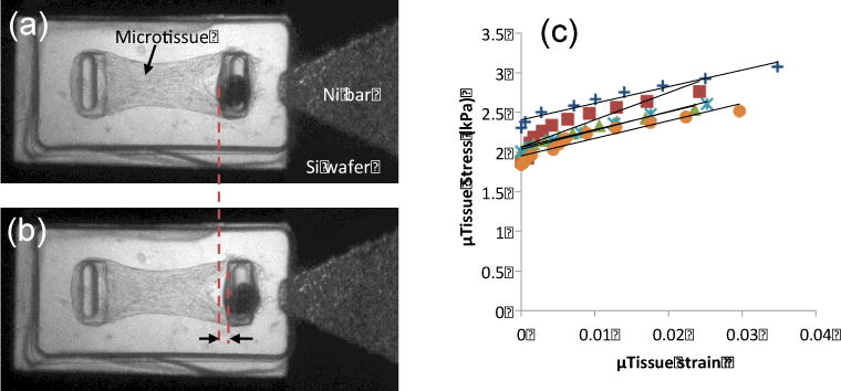
(a) 3T3 fibroblast populated collagen microtissue on MMT with lid device. (b) Application of a 20 mT external field displaces the magnetic pillar by 18 μm from its initial position (Red dashed lines and black arrows) and causes a 2% strain. The tissue force as measured by the left pillar increases by 5 μN. (c) Examples of resulting quasi-static stress-strain curves for a representative set of microtissues from a single MMT array.
For this data set, the resulting average elastic modulus was 30 ± 6 kPa (N = 7). To benchmark these results against our previously established magnetic tweezer-based method to measure stiffness,15, 17 we cultured additional microtissues on MMTs for 2 days and measured their moduli with our magnetic tweezers, obtaining 29 ± 9 kPa (N = 11). The good agreement between the two approaches (p > 0.4), indicates that the lid-based magnetic stretching provides a reliable way to measure quasi-static mechanical properties of microtissues.
3.4 Dynamic Loading
The dynamic loading capacity of the lid device was evaluated by applying a sinusoidal magnetic external field of amplitude 20 mT at 1 Hz to the lid devices on MMTs. To verify that the microtissues underwent periodic actuation in response to this stimulation, we observed the microtissues’ for brief intervals (~15 sec) while recording their motion at 100 frames/sec. Figure 7(a) shows the left pillar displacement (microtissue force) and overall length (difference in pillar positions) vs. time for a microtissue following initiation of actuation. Both the force and length are predominantly sinusoidal with second harmonic content < 6% of the 2 Hz fundamental, similar to that observed for AC actuation of magnetic pillars without microtissues (Fig. 5). We observed temporary elongation of the microtissues, consistent with that observed over longer periods with magnetic tweezers.15 As noted previously, this plastic deformation is likely due to increased alignment of the collagen fibrils during stretch.
Fig. 7.
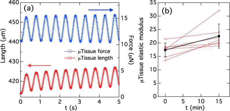
(a) Tracking of dynamic actuation of a microtissue with lid device, showing 2 Hz modulation in force on microtissue (blue trace) and length (red trace) in response to a 1 Hz AC external magnetic field. The tissue length is reported as the inner edge-to-edge separation between the pillars. (b) Change in elastic modulus of microtissues cultured for one day and then stimulated at 2 Hz (1 Hz external field) for 15 min. (red traces). Results are taken from two MMT arrays under identical conditions. All microtissues showed an increased stiffness. The average stiffness before and after stimulation (black symbols) showed a 31% increase.
To test the lids’ potential for longer-term actuation, the elastic modulus of a set of microtissues was first measured by quasi-static loading with the lid as described in Section 3.3. Cyclic loading at 2 Hz (1 Hz external field) was then applied simultaneously to the tissues for 15 min, and the stiffness was re-measured. While there was some variability in the degree of stiffness change, all microtissues measured exhibited an increase in modulus (Fig. 7(b), with an average increase of 31%, again comparable to results obtained previously via the much more laborious process of serial actuation of individual microtissues with our magnetic tweezers.15
4 Discussion
Current cutting edge methods of tissue engineering range from bioreactors9, 22 to 3D printing.23–26 Arrays of microfabricated 100 μm-scale devices, such as the μTUG-based microtissue platform employed here, can provide an excellent approach for a range of experimentation on small-scale multicellular 3D constructs, from fundamental studies of tissue biomechanics and cellular organization to drug screening and other diagnostics. In many applications that can be envisioned, however, the ability to apply in-situ mechanical conditioning and to carry out mechanical testing are crucial ingredients, both to probe mechanobiology and to influence the development and/or maturation of the tissue constructs.27–30 We have previously demonstrated the value of magnetically actuated microtissues for mechanobiological studies.15–17 In this work, we have demonstrated the ability of our magnetic lid device, when paired with MMTs, to provide actuation to many microtissues in parallel that is comparable to that obtained previously on single microtissues with magnetic tweezers.15
The primary engineering requirement for the Lid was for it to recapitulate the magnitude of force generation and level of control that an electromagnetic tweezer provides when paired with MMT devices. The use of SU-8-based templated electrodeposition of Ni, which has been well-developed in the context of MEMS devices,31, 32 provided a clean way to fabricate 100-μm to mm scale biocompatible magnetic components that are thick enough (t ~ 60–100 μm) to acquire sufficient magnetic moments in modest ~30–50 mT external magnetic fields and to generate the 10s of μN-scale forces needed to actuate our microtissues.
In our previous experiments, we used a quasi-static loading approach to determine the stiffness of the microtissues.15 Results presented in this paper demonstrate that this capability is very effectively reproduced using the Lids, and that the system can actuate multiple microtissues simultaneously at physiologically relevant frequencies. This opens the possibility of studies of maturation and other longer-term effects that are influenced by a dynamic mechanical environment. Because of the non-invasive nature of the magnetic actuation approach, long-term stimulation protocols can be readily implemented, e.g. by the simple expedient of mounting an electromagnet in an incubator that need only generate a spatially uniform (if time-varying) field.
Our current visualization experiments employed conventional microscope-based imaging approaches that are best applied to single microtissues. This is more than adequate for a wide range of experiments where it is not necessary to monitor mechanical properties during stimulation, and where, as seen in the AC stimulation experiment presented here, intrinsic variability in the graded response of the microtissues to mechanical actuation dominates the spread in the strength of the actuation profiles produced by the lid array. However, if real-time monitoring of time evolution is required, this system could be paired with a variety of parallel imaging approaches that can observe multiple microtissues simultaneously.
5 Summary
In the present work, we have demonstrated the ability of patterned arrays of mm-scale magnetic bars to provide chronic stimulation at physiologically relevant frequencies to arrays of microtissues. These magnetic arrays are constructed using standard Si-based photolithography and micropatterning, and represent a simple and compact device for tissue mechanical conditioning and testing. The use of local magnetic features to transduce a uniform external magnetic field into the field gradients needed to produce forces on magnetic microtissue devices provides a flexible and non-contact mode of mechanical actuation that should be applicable to a variety of cell types. This approach can advance the field of tissue biomechanics, and potentially enable investigations of tissue maturation on the microscale. Examples of potential applications include dermal tissue, arterial and airway smooth muscle, and skeletal muscle, all of which have major biomechanical functions and responses to loading that are clinically important but which require further elucidation.
Acknowledgments
We thank C. S. Chen for providing the PDMS molds used to produce the MMTs. This work was supported in part by NIH Grant HL-90747. F X. acknowledges support of the Johns Hopkins Yeung Center, and A. S. L. acknowledges support from a NSF IGERT fellowship.
References
- 1.Krawiec JT, Vorp DA. Biomaterials. 2012;33:3388–3400. doi: 10.1016/j.biomaterials.2012.01.014. [DOI] [PubMed] [Google Scholar]
- 2.Bichara DA, O’Sullivan NA, Pomerantseva I, Zhao X, Sundback CA, Vacanti JP, Randolph MA. Tissue Engineering Part B-Reviews. 2012;18:51–61. doi: 10.1089/ten.TEB.2011.0326. [DOI] [PubMed] [Google Scholar]
- 3.Cummings CL, Gawlitta D, Nerem RM, Stegemann JP. Biomaterials. 2004;25:3699–3706. doi: 10.1016/j.biomaterials.2003.10.073. [DOI] [PubMed] [Google Scholar]
- 4.Tulloch NL, Muskheli V, Razumova MV, Korte FS, Regnier M, Hauch KD, Pabon L, Reinecke H, Murry CE. Circ Res. 2011;109:47–U195. doi: 10.1161/CIRCRESAHA.110.237206. [DOI] [PMC free article] [PubMed] [Google Scholar]
- 5.Riehl BD, Park JH, Kwon IK, Lim JY. Tissue Engineering Part B-Reviews. 2012;18:288–300. doi: 10.1089/ten.teb.2011.0465. [DOI] [PMC free article] [PubMed] [Google Scholar]
- 6.Diamantouros SE, Hurtado-Aguilar LG, Schmitz-Rode T, Mela P, Jockenhoevel S. Ann Biomed Eng. 2013;41:1979–1989. doi: 10.1007/s10439-013-0823-5. [DOI] [PubMed] [Google Scholar]
- 7.Isenberg BC, Williams C, Tranquillo RT. Circ Res. 2006;98:25–35. doi: 10.1161/01.RES.0000196867.12470.84. [DOI] [PubMed] [Google Scholar]
- 8.Kurobe H, Maxfield MW, Breuer CK, Shinoka T. Stem Cells Translational Medicine. 2012;1:566–571. doi: 10.5966/sctm.2012-0044. [DOI] [PMC free article] [PubMed] [Google Scholar]
- 9.Rauh J, Milan F, Gunther KP, Stiehler M. Tissue Engineering Part B-Reviews. 2011;17:263–280. doi: 10.1089/ten.TEB.2010.0612. [DOI] [PubMed] [Google Scholar]
- 10.Legant WR, Pathak A, Yang MT, Deshpande VS, McMeeking RM, Chen CS. Proc Natl Acad Sci U S A. 2009;106:10097–10102. doi: 10.1073/pnas.0900174106. [DOI] [PMC free article] [PubMed] [Google Scholar]
- 11.Serrao GW, Turnbull IC, Ancukiewicz D, Kim DE, Kao E, Cashman TJ, Hadri L, Hajjar RJ, Costa KD. Tissue Eng Part A. 2012;18:1322–1333. doi: 10.1089/ten.tea.2011.0278. [DOI] [PMC free article] [PubMed] [Google Scholar]
- 12.Legant WR, Chen CS, Vogel V. Integrative Biology. 2012;4:1164–1174. doi: 10.1039/c2ib20059g. [DOI] [PMC free article] [PubMed] [Google Scholar]
- 13.West AR, Zaman N, Cole DJ, Walker MJ, Legant WR, Boudou T, Chen CS, Favreau JT, Gaudette GR, Cowley EA, Maksym GN. Am J Physiol-Lung Cell Mol Physiol. 2013;304:L4–L16. doi: 10.1152/ajplung.00168.2012. [DOI] [PMC free article] [PubMed] [Google Scholar]
- 14.Boudou T, Legant WR, Mu AB, Borochin MA, Thavandiran N, Radisic M, Zandstra PW, Epstein JA, Margulies KB, Chen CS. Tissue Eng Part A. 2012;18:910–919. doi: 10.1089/ten.tea.2011.0341. [DOI] [PMC free article] [PubMed] [Google Scholar]
- 15.Zhao R, Boudou T, Wang WG, Chen CS, Reich DH. Adv Mater. 2013;25:1699–1705. doi: 10.1002/adma.201203585. [DOI] [PMC free article] [PubMed] [Google Scholar]
- 16.Zhao R, Boudou T, Wang WG, Chen CS, Reich DH. J Appl Phys. 2014;115:172616. doi: 10.1063/1.4870918. [DOI] [PMC free article] [PubMed] [Google Scholar]
- 17.Zhao R, Chen CS, Reich DH. Biomaterials. 2014;35:5056–5064. doi: 10.1016/j.biomaterials.2014.02.020. [DOI] [PMC free article] [PubMed] [Google Scholar]
- 18.Lin YC, Kramer CM, Chen CS, Reich DH. Nanotechnology. 2012;23:075101. doi: 10.1088/0957-4484/23/7/075101. [DOI] [PMC free article] [PubMed] [Google Scholar]
- 19.Wasserman JL, Lucas K, Lee SH, Ashton A, Crowl CT, Markovic N. Rev Sci Instrum. 2008;79:073909. doi: 10.1063/1.2960573. [DOI] [PubMed] [Google Scholar]
- 20.Zhao R, Simmons CA. J Biomech. 2012;45:76–82. doi: 10.1016/j.jbiomech.2011.10.003. [DOI] [PubMed] [Google Scholar]
- 21.Crangle J, Goodman GM. Proceedings of the Royal Society of London Series a-Mathematical and Physical Sciences. 1971;321:477–491. [Google Scholar]
- 22.Badylak SF, Taylor D, Uygun K. Annual Review of Biomedical Engineering, Vol 13. 2011;13:27–53. doi: 10.1146/annurev-bioeng-071910-124743. [DOI] [PMC free article] [PubMed] [Google Scholar]
- 23.Mannoor MS, Jiang Z, James T, Kong YL, Malatesta KA, Soboyejo WO, Verma N, Gracias DH, McAlpine MC. Nano Lett. 2013;13:2634–2639. doi: 10.1021/nl4007744. [DOI] [PMC free article] [PubMed] [Google Scholar]
- 24.Gauvin R, Chen YC, Lee JW, Soman P, Zorlutuna P, Nichol JW, Bae H, Chen SC, Khademhosseini A. Biomaterials. 2012;33:3824–3834. doi: 10.1016/j.biomaterials.2012.01.048. [DOI] [PMC free article] [PubMed] [Google Scholar]
- 25.Miller JS, Stevens KR, Yang MT, Baker BM, Nguyen DHT, Cohen DM, Toro E, Chen AA, Galie PA, Yu X, Chaturvedi R, Bhatia SN, Chen CS. Nat Mater. 2012;11:768–774. doi: 10.1038/nmat3357. [DOI] [PMC free article] [PubMed] [Google Scholar]
- 26.Murphy SV, Atala A. Nat Biotechnol. 2014;32:773–785. doi: 10.1038/nbt.2958. [DOI] [PubMed] [Google Scholar]
- 27.Barron V, Lyons E, Stenson-Cox C, McHugh PE, Pandit A. Ann Biomed Eng. 2003;31:1017–1030. doi: 10.1114/1.1603260. [DOI] [PubMed] [Google Scholar]
- 28.Seliktar D, Black RA, Vito RP, Nerem RM. Ann Biomed Eng. 2000;28:351–362. doi: 10.1114/1.275. [DOI] [PubMed] [Google Scholar]
- 29.Apte SS, Paul A, Prakash S, Shum-Tim D. Future cardiology. 2011;7:77–97. doi: 10.2217/fca.10.120. [DOI] [PubMed] [Google Scholar]
- 30.Hoerstrup SP, Sodian R, Sperling JS, Vacanti JP, Mayer JE. Tissue Eng. 2000;6:75–79. doi: 10.1089/107632700320919. [DOI] [PubMed] [Google Scholar]
- 31.Ho CH, Chin KP, Yang CR, Wu HM, Chen SL. Sensors and Actuators a-Physical. 2002;102:130–138. [Google Scholar]
- 32.Lorenz H, Despont M, Vettiger P, Renaud P. Microsystem Technologies. 1998;4:143–146. [Google Scholar]


