Abstract
Magnetic localization has been used in a variety of applications, including the medical field. Small magnetic tracers are often modeled as dipoles and localization has been achieved by solving well-defined dipole equations. However, in practice, the precise calculation of the tracer location not only depends on solving the highly nonlinear dipole equations through numerical algorithms but also on the precision of the magnetic sensor, accuracy of the tracer magnetization, and the earth magnetic field (EMF) measurements. We have developed and implemented a comprehensive calibration method that addresses all of the aforementioned factors. We evaluated this method in a bench-top setting by moving the tracer along controlled trajectories. We also conducted several experiments to track the tongue movement in a human subject.
I. Introduction
Magnetic localization has been used as an effective tool to track the movement of the tongue [1, 2], monitoring of the pill transit during swallowing [3], and capsule endoscopy [4]. In all of these applications, one or more magnetic sources (in the form of a permanent magnet or coil) is placed on the region of interest (ROI), and the movement of the magnet, and thus the movement of the ROI, is tracked using the magnetic sensors (or coils) mounted in the vicinity of the source. If the ROI happens to be inside the human body, it is preferable to use a permanent magnet as the tracer since it should operate in a wireless fashion. If the dimensions of the magnetic tracer is small and its distance to the sensors is far enough, it can be modeled as a magnetic dipole, reducing the complexity of the localization problem to solving a well-known five dimensional equation (1). Depending on the required precision, size of the ROI, and the required computational speed, different methodologies have been proposed for solving the dipole localization equation.
The localization solutions have been divided into two general categories: a) linear or closed-form formulas and b) non-linear optimization approaches. These methods are quite different in terms of resolution, localization volume, accumulated error, sensitivity to noise and interference, minimum number of required sensors, and computational cost. Closed-form approaches have lower computational cost and are not vulnerable to volatility from the initial search point of the optimization algorithms. Wynn suggested an approach that can be implemented by only three 3-axial magnetic sensors, arranged in a coplanar triangle to form a tensor magnetic gradiometer [5]. However, this method showed a high localization error. Hu et al. reduced the complexity of the localization problem into solving 15 linear equations that can be obtained from five, 3-axial sensors [6]. However, these methods fail to provide high accuracy as compared to the non-linear optimization methods.
The non-linear optimization methods typically start from an initial guess and iteratively minimize an error function. DIviding RECTangles (DIRECT), Multilevel Coordinate Search (MCS), Levenberg–Marquardt (LM), Nelder-Mead (NM), Powell, and Particle Swarm (PS) are some of the optimization methods that have been used for magnetic localization. Our previous investigations showed that the NM and Powell optimizations can provide acceptable precision (less than 1 mm error) in a stationary setup [1]. On the other hand, Hu et al. have found the LM to be the most effective method for their application of tracking a pill in the gastrointestinal tract [7].
Nevertheless, in practice the accurate localization of a magnet is not only dependent on the optimization approach, but also on the precision of the magnetic sensors (including their calibration), accurate measurements of the tracer magnetization, and the earth magnetic field (EMF). Each manufactured sensor is slightly different from others, and they measure differently in response to identical magnetic fields. Hence, they need to be calibrated. There are very few literatures that address the calibration issue, one of which is [7]. The authors only take into account some of the sensor’s parameters, such as sensitivity, nonlinearity, position, and orientation. However, they do not consider the interactions between these parameters. Furthermore, the proposed method is cumbersome, since every parameter has to be determined individually through a separate experiment.
In order to address these issues and improve the accuracy of the localization, we have proposed a comprehensive method that takes into account a variety of the sensor parameters, such as gain, offset), position, rotations, magnetic tracer’s residual flux density (Br) and rotation, and the EMF, all at once. We have successfully examined the accuracy of our method in a bench-top setting that included multiple sensors. The localization area was chosen to be close to the size of the oral cavity since our ultimate goal is to precisely track tongue movements. We utilized a high precision 3-D robotic arm to evaluate the accuracy of the system. Furthermore, repeatable trajectories from a human subject were recorded and compared with similar results reported in the literature.
II. Methodology
A. Mathematical Model of a Permanent Magnetic Dipole
Fig. 1 shows a cylindrical magnet with thickness l, diameter d, and residual magnetic strength Br, at location a = (ax,ay,az). The orientation of the dipole moment, m, is determined by θ and φ. The static magnetic flux density, B, generated by this magnet, measured at the sensor location s = (sx,sy,sz), at a distance much greater than l and d, fits in the magnetic dipole model, given by the following:
| (1) |
where m = [m·sin(θ)cos(φ), m·sin(θ)sin(φ), m·cos(θ)] is the magnetic moment vector of the dipole, and m = πBrd2l/(4μ0) is the magnitude of m [1].
Fig. 1.
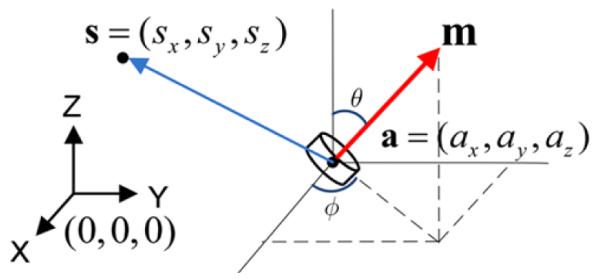
Vector representation of the magnetic dipole model.
In order to localize the magnet, this 5th order equation with 5 variables, 3 for position (ax,ay,az) and 2 for orientation (θ and φ), needs to be solved using the samples that are collected from the magnetic sensor array. This is also known as solving the inverse problem.
We can define the mean square error between Bsensor (output vector from the sensor) and B (the estimate), as the fitness function (F)
| (2) |
The smaller F is, the more precise the estimated position and orientation of the magnetic tracer will be.
B. Simulation of the Optimization Algorithm
Our intention was to develop a comprehensive algorithm for calibrating the sensors as opposed to finding the best solution for (1) and (2). Therefore, we chose the NM algorithm, which demonstrated an acceptable performance in our previous work [1]. In the simulations, we assumed that the sensors’ location and orientation are exactly known. The magnetic field was then calculated at each sensor position while the tracer was moved along a known trajectory. Those ideal fields were fed into the NM algorithm, which in turn reconstructed the localized trajectory. Fig. 2 shows a typical simulated trajectory in blue, and its reconstruction in red. The root-mean-square (RMS) of the error for this trajectory was 4.17·10−6 mm. Comparing this result with the published literature, which led to ~0.9 mm error at its best, yields that the major error source was not the optimization algorithms per se, but rather the practical issues involving the sensor calibration and the EMF.
Fig. 2.
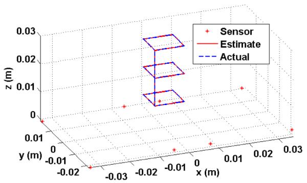
A simulated trajectory that was localized through NM method.
C. Comprehensive Calibration Algorithm
In order to consider the important practical issues (including non-idealities), such as the sensors’ gain and offset, position (x, y, z), orientation (θ, φ), and the EMF, we have modified the fitness function (2) as
| (3) |
where G and O are the gain and offset coefficients in 3-D, respectively, and [α,β,γ] represents the 3-D rotation matrix of Euler angles. Therefore, we consider 18 coefficients for each sensor, and since we are using 8 sensors in our study, we must collect a total of 144 coefficients.
In measurements, we moved the tracer over a precise trajectory, using a robotic arm, while simultaneously recording the 3-axial readings from 8 sensors (Bsensor) at every 50 to 400 μm displacement of the tracer. Then we calculated the theoretical B at each measured point and tried to minimize the error in the fitness function (3). In order to reduce the optimization time and prevent the optimizer from being stuck in local minima, we provided appropriate starting points for the parameters being optimized. For instance, we measured the position (with the robotic arm), gain, and offsets of the sensors (through spherical method in section II.D); the initial position and magnetic moment vector (Br, d and l provided by the manufacturer) of the magnetic tracer; and the EMF (measured before performing the experiment).
D. The Spherical Method for Coarse Calibration
This method can be used as a first estimate of the gain and offset coefficients of the sensors [8]. This method takes advantage of the homogeneity of the EMF, which is approximately 15 milligauss over a 30 cm cube. We randomly rotate the sensors along many different orientations to produce many outputs from the fixed background field. When projected onto a 3D space, the outputs form spheroids with each axis corresponding to a gain coefficient, and the displacement from the origin being the offset. After applying proper coefficients, the spheres are aligned, i.e. centered at the origin with equal axes. Figs. 3a and 3b show the non-calibrated and calibrated outputs from four sensors, respectively.
Fig. 3.
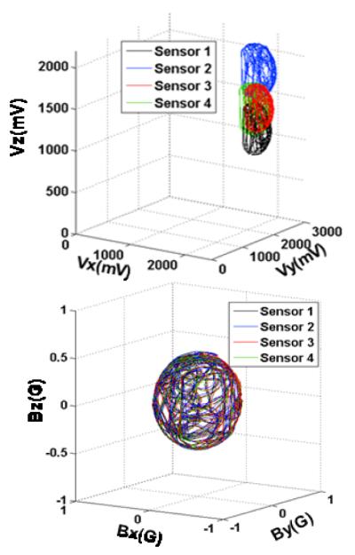
Magnetic field measured by 4 sensors (a) before and (b) after spherical calibration.
III. System Overview
The experimental setup for magnetic calibration and localization was identical to the one presented in [1]. A small cylindrical-shaped permanent magnet (∅3.1 mm × 1.5 mm, weight = 0.09 g, Br,max = 13200 G) (K&J, Jamison, PA), which was used as the tracer, was mounted on a 3-D robotic arm (VELMEX, Bloomfield, NY) with 3.75 μm spatial resolution. A graphical user interface (GUI) was developed to control the arm. Eight 3-axial magnetic sensors (AMI306, AICHI STEEL, Japan) were used to track the tracer position. Each sensor module accommodates three sensor elements and their controller chip, which includes an amplifier, a 12-bit ADC, and an I2C serial interface.
A. Magnetic Sensor Data Acquisition Hardware
Data from 8 magnetic sensors was transmitted wirelessly to a PC via two identical control units. Each unit controlled the information from four sensor modules, and each unit included a system-on-a-chip (SoC) microcontroller (MCU) and transceiver (CC2510, Texas Instruments, Dallas, TX). Initially, the wireless communication links between the two transmitters (Tx) and receivers (Rx) (CC2510 was used as both Tx and Rx) were set to different RF channels around 2.4 GHz ISM-band, and the communication link was verified through handshaking. Then, the MCU on each module read the digitized samples from the sensors at a rate of 50 samples/s through the I2C protocol and loaded them into a payload of 256 bytes. The two receivers were connected via individual USB ports to the same PC that was used to control the robotic arm to transfer the acquired sensor data for further processing and localization.
B. Robotic Arm and Integrative GUI
A custom-made GUI was developed in the LabVIEW environment (National Instruments, Austin, TX) to precisely control the robotic arm in three orthogonal directions (x,y,z) in a range of 15×15×15 cm3 with 3.75 μm accuracy and store the data points for off-line analysis. This GUI could also acquire and fuse the information from the two wireless receivers and associate the position of the tracer with the recorded magnetic field at any moment.
IV. Experimental Results
A. Bench-top Experiments
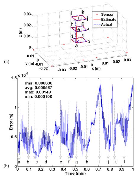
After obtaining the calibration parameters, we ran several trajectories with the robotic arm to examine the precision of our system, e.g. Fig. 4, utilizing the parameters obtained from the comprehensive optimization method. For most of the trajectories that were within 3 cm from the sensors’ plane, the RMS-error was less than 0.5 mm. When the tracer’s distance from the sensor plane exceeded the 3 cm threshold, the RMS-error increased dramatically. This was mainly due to the drop in the signal to noise ratio (SNR) of the magnetic field measured by the sensors. Fig. 5 illustrates a helical trajectory with 1 cm diameter and total height of 3.5 cm. The total RMS-error for this path was 0.9 mm. However, most of the error was attributed to when the tracer moved further from the sensors, to above 3 cm. The RMS-error for the distances less than 3 cm was only 0.5 mm, which is almost half of the total RMS error.
Fig. 4.
(a) A Trajectory that was followed by the robotic arm and used for comprehensive calibration, (b) the associated error in the (a) trajectory.
Fig. 5.
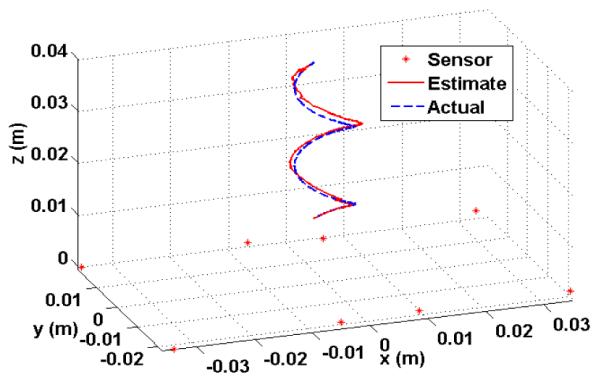
A helical trajectory, 1 cm in diameter, that was generated by the robotic arm (blue dashed-line) and the reconstructed path (red line).
B. Human Subject Experiments
A permanent magnet was temporarily attached to the subject’s tongue (one of the co-authors) about 1 cm from the tongue apex using tissue adhesives. The subject was asked to fixate his forehead against the head support (Fig. 6a) during the experiment such that the tracer movements could only be attributed to the tongue motion as opposed to the head motion. Sensors were positioned under a Plexiglas sheet, about 1 cm below the subject’s chin, along two parallel lines (Fig. 6b). Data from sensors was wirelessly transmitted to a PC via the control unit shown in Fig. 6c. The subject was asked to produce simple combinations of vowels (V) and consonants (C). Fig. 7a shows the trajectory of the tongue when the subject was asked to pronounce two consecutive VCV, i.e., [ASA#A∫A]. Fig. 7b shows a similar VCV produced by a subject, reported in [9], and the trajectory reconstructed by a commercial system, AG-100 (Carstens, Germany). It can be seen in this figure that our magnetic tongue tracking system was capable of reproducing a comparable result. Furthermore, when the subject was asked to repeat the same VCV pattern several times, the system reconstructed a repeated pattern along the same trajectory.
Fig. 6.
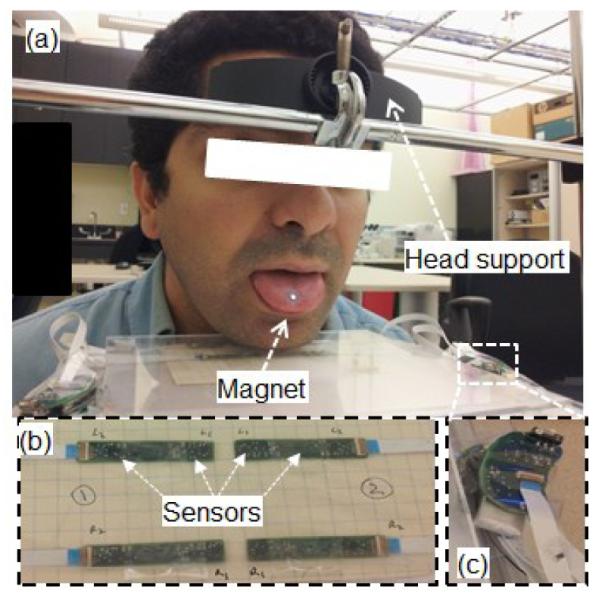
(a) The experimental setup for human trials, (b) Eight 3-axial sensor modules placed under the chin, and (c) the CC2510 wireless MCU.
Fig. 7.
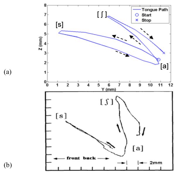
A repeatable trajectory of the tongue movement for producing [asa#a∫a] reconstructed with (a) our system, (b) AG-100 (courtesy of [9]).
V. Discussion and Conclusion
To the best of our knowledge, no method has been reported that takes into consideration all the parameters that practically play a role in magnetic localization in a single calibration. Moreover, the proposed spherical measurement method performs a coarse calibration that provides starting points for the optimizer before the comprehensive calibration, and tremendously helps it by avoiding the local minima. Hu et al. [7], is the only other literature that discusses the sensor calibration. However, their method does not comprehensively address all the parameters included in this paper. Since their method calibrates one parameter at a time, it is rather cumbersome and does not take into account the interactions between parameters. Precision of the reference instrument (the robotic arm in our case) is key to the overall resolution of the localization. Hu et al. utilized Fastrak (Polhemus, USA) as their reference instrument, which has a tracking accuracy of ~0.77 mm. Hence their obtained accuracy was always above this level. We intend to investigate the effects of various sensor arrangements, and conduct additional experiments on more human subjects.
Acknowledgments
This work was supported in part by the National Institute of Biomedical Imaging and Bioengineering grant 1RC1EB010915 and the National Science Foundation awards CBET-0828882 and IIS-0803184.
References
- [1].Cheng C, Huo X, Ghovanloo M. Towards a magnetic localization system for 3-D tracking of tongue movements in speech-language therapy. Proc. IEEE 31st Eng. in Med. and Biol. Conf.; Aug. 2009; pp. 563–566. [DOI] [PMC free article] [PubMed] [Google Scholar]
- [2].Katz WF, McNeil MR, Garst DM. Treating apraxia of speech (AOS) with EMA-supplied visual augmented feedback. Aphasiology. 2010 Jun.24(no. 6-8):826–837. [Google Scholar]
- [3].Weitschiles W, Kosch O, Mönnikes H, Trahms L. Magnetic Marker Monitoring: An application of biomagnetic measurement instrumentation and principles for the determination of the gastrointestinal behavior of magnetically marked solid dosage forms. Adv. Drug Deliv. Rev. 2005 Jun.57(no. 8):1210–1222. doi: 10.1016/j.addr.2005.01.025. [DOI] [PubMed] [Google Scholar]
- [4].Hu C, Meng MQ-H, Mandal M. Efficient magnetic localization and orientation technique for capsule endoscopy. Int. J. Inf. Acquisition. 2005 Aug.2(no. 1):23–36. [Google Scholar]
- [5].Wynn WM. Method of magnetic source localization using gradient tensor components and rate tensor components. 5777477 U.S. Patent. 1998
- [6].Hu C, Meng MQ-H, Mandal M. A linear algorithm for tracing magnet’s position and orientation by using 3-axis magnetic sensors. IEEE Trans. Magnetics. 2007 Dec.43(no. 12):4096–4101. [Google Scholar]
- [7].Hu C, Li M, Song S, Yang W, Zhang R, Meng MQ-H. A cubic 3-axis magnetic sensor array for wirelessly tracking magnet position and orientation. IEEE Sensors J. 2010 May;10(no. 5):903–913. [Google Scholar]
- [8].Zhang X, Gao L. A novel auto-calibration method for the vector magnetometer. Proc. IEEE 9th Elec. Meas. & Inst. Conf..pp. 1-145–1-150. [Google Scholar]
- [9].Katz WF, Bharadwaj SV, Carstens B. Electromagnetic articulography treatment for an adult with Broca’s Aphasia and Apraxia of Speech. J Speech Lang Hear Res. 1999 Dec.42(no. 6):1355–1366. doi: 10.1044/jslhr.4206.1355. [DOI] [PubMed] [Google Scholar]


