Abstract
Damage response of brittle curved structures subject to cyclic Hertzian indentation was investigated. Specimens were fabricated by bisecting cylindrical quartz glass hollow tubes. The resulting hemi-cylindrical glass shells were bonded internally and at the edges to polymeric supporting structures and loaded axially in water on the outer circumference with a spherical tungsten carbide indenter. Critical loads and number of cycles to initiate and propagate near-contact cone cracks and far-field flexure radial cracks to failure were recorded. Flat quartz glass plates on polymer substrates were tested as a control group. Our findings showed that cone cracks form at lower loads, and can propagate through the quartz layer to the quartz/polymer interface at lower number of cycles, in the curved specimens relative to their flat counterparts. Flexural radial cracks require a higher load to initiate in the curved specimens relative to flat structures. These radial cracks can propagate rapidly to the margins, the flat edges of the bisecting plane, under cyclic loading at relatively low loads, owing to mechanical fatigue and a greater spatial range of tensile stresses in curved structures.
Keywords: Fatigue, Fracture, Curved structure, Bilayer
I. INTRODUCTION
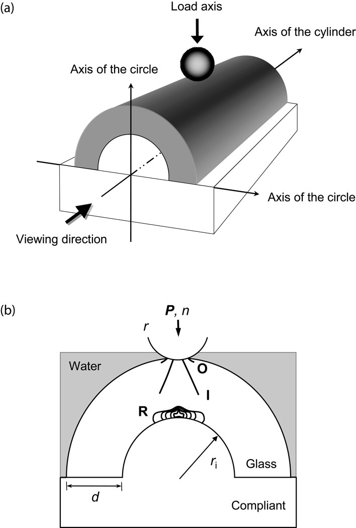
Brittle layers on polymeric substrates are relevant to a wide range of engineering structures, including biomedical prostheses.[1–3] Full-coverage ceramic dental restorations (crowns) are a special case in point. Although there has been immense amount of study concerning the fracture of crowns, the bulk of the work reported in the literature has focused on model flat ceramics/polymer bilayers loaded on the top surface with a spherical indenter.[1, 3] Teeth and crowns exhibit pronounced curvature and shape irregularities, which can substantially alter stress state and thereby influence critical loads to initiate and propagate cracks in the brittle layers. Recently, several studies have extended to dome-like polymer-filled glass shells using single-cycle load-to-fracture Hertzian indentation in dry environments.[4–9] However, crowns are subject to repeated chewing function in liquid environments which this study takes into consideration. Accordingly, we are investigating the initiation and failure conditions of curved surfaces as a function of number of cycles using hemi-cylindrical shells (by bisecting cylindrical tubes through their diameter along the cylinder axis) supported by compliant bases cyclically loaded on the outer circumference with a spherical indenter while in water [Fig. 1(a)]. Flexural radial cracks can initiate at the interface of the inner circumference of the cylinder. Since the cylindrical shell is easier to flex along the axis of the cylinder than the axis of the circle, this leads to preferential radial fracture in the plane parallel or near parallel to the axis of the circle [Fig. 1(a)]. Contact induced cone cracks also tend to initiate in the plane near parallel to the axis of the circle, owing to the high tensile stresses associated with the steep curvature in the direction of the axis of the circle [Fig. 1(a)]. The current experimental setup enables direct observation of fracture evolution, from initiation to failure, for both radial and cone cracks.
Figure 1.
(a) Schematic illustration of specimen geometry and indentation testing arrangement. Cylindrical quartz glass tubes of thickness d and inner radius ri = 4 mm are bisected in the direction of the axis of the cylinder, filled with polymer-based material and bonded to a polycarbonate base. (b) Crack geometry for cyclic contact on hemi-cylindrical quartz glass shell on polymer bilayers with a tungsten carbide sphere of radius r at load P for number of cycles n. Showing three crack modes: outer cone cracks (O), inner cone cracks (I), and bottom surface radial cracks (R). The junctions of the bisected cylinder with the polycarbonate base is designated as the margins.
In the case of curved brittle structures in contact with blunt indenters in single-cycle loading in dry environments, damage takes the form of a competition between outer cone cracks that initiate from surface flaws outside the maximum contact and radial cracks that initiate from surface flaws at the inner circumference [Fig. 1(b)].[4] Both crack types are accelerated by slow crack growth (SCG).[10, 11] In water, cyclic loading can lead to the generation of a new kind of cone cracks, inner cone cracks, that form inside the expanding contact. These cracks propagate downward quickly at a steeper angle relative to their outer counterparts [Fig. 1(b)].[12] The inner cone cracks are accelerated by hydraulic pumping (mechanical fatigue) in addition to SCG.[12, 13] In this study, we examine the competition between the various fracture modes in curved brittle bilayers subject to cyclic loading with a spherical indenter while immersed in water.
II. METHODS
A. Sample preparation
The properties of the materials used in this study is tabulated in Table 1. Hollow quartz glass tubes (Gaithersburg Glass, Gaithersburg, MD) with outer radius ro = 5 mm, inner radius ri = 4 mm, and wall thickness d = 1 mm were used to fabricate curved brittle layers on compliant substrate structures. Solid epoxy rods were fabricated using hollow glass tubes (ro = 5 mm, ri = 4 mm) as molds. Slow cure epoxy (Leco, St. Joseph, MI) was mixed with hardener (Leco, St. Joseph, MI) at a 7:1 ratio using a magnetic stirrer for 20 mins. The epoxy-hardener mixture was poured into the glass molds and cured for 48 hours. The resulting epoxy rods were bonded to hemi-cylindrical glass tubes using the same epoxy-hardener mixture. The lower portion of the epoxy rod was polished away and the resulting epoxy-filled hemi-cylindrical glass tube is then bonded onto 12 mm thick polycarbonate (Hyzod, AlN Plastics, Norfolk, VA) substrate with epoxy-hardener adhesive [Fig. 1(a)]. This way only negligible residual stresses were introduced through the cure of a thin (~50 µm) epoxy adhesive layer.
Table 1.
Properties of representative materials†.
| Materials | Modulus E (GPa) |
Hardness H (GPa) |
Toughness T (MPa·m½) |
Strength σ (MPa) |
|---|---|---|---|---|
| Quartz glass (99.9%)‡ | 71 | 6.5 | - | ~80 |
| Sodalime glass‡ | 70 | 5.2 | 0.67 | - |
| Epoxy | 3.5 | 0.4 | - | - |
| Polycarbonate‡ | 2.3 | 0.3 | - | - |
Uncertainties in E estimated at ~5%, H~10%, and T~20%.
Materials for which supplementary data were obtained.
Quartz glass plates, 35×25×1 mm in dimension, were used to fabricate flat brittle bilayers for comparative studies. The plates were bonded to 12 mm thick polycarbonate substrates with a thin layer (50 µm) of epoxy adhesive.
All glass specimens were etched with 10% hydrofluoric acid solution for 30 seconds to remove surface flaws. Then, to produce an uniform flaw density, the top, contact surfaces of glass plates and hemi-cylindrical shells were abraded with 600-grit SiC particles, while the bottom surfaces were grit-blasted with Al2O3 particles (means particle size: 50 µm) for 5 seconds.
B. Fatigue testing
Fatigue damage in curved glass/polymer bilayers was introduced using a Hertzian test configuration in water [Fig. 1(a)]. Normal axial force P was applied on the specimen’s outer circumference through a tungsten carbide (WC) sphere (r = 1.6 mm) with a mouth-motion simulator (Elf 3300, EnduraTEC Division of Bose, Minnetonka, MN). Care was taken to align the load and specimen axes. The chewing frequency and loading-unloading rate were 1.5 Hz and 1000 N/s, respectively. Each load cycle consisted of the indenter contacting the specimen, loading to a maximum, holding for 0.2 seconds, unloading, and liftoff (0.5 mm above the specimen surface). The load range studied varied from 60 – 500 N, covering most of the nominal biting force range 35 – 300 N.[14] The damage modes in the glass/polymer bilayers were monitored in-situ, viewing from the direction of the cylinder axis, during the fatigue test using a video camera system (Canon XL1, Canon, Lake Success, NY).
C. Definitions of failure
Two types of failure are described here: through-thickness failure and catastrophic failure. Through-thickness failure is defined when one of the crack systems, initiated either from the top-surface (i.e. outer and/or inner cone cracks) or from the bottom-surface (i.e. radial cracks), penetrates through the entire layer thickness, or two crack systems initiated from top and bottom surfaces intersect each other, resulting in through-thickness fracture. Catastrophic failure is defined when bottom radial cracks extend to the margins, resulting in bulk fracture[14] of the system. The junctions of the bisected cylinder with the polycarbonate base is designated as the margins.
III. RESULTS
A. Crack evolution
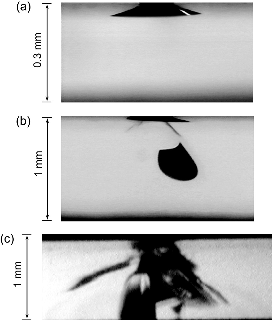
Figure 2 is a sequence of video clips showing crack evolution as a function of the number of cycles in a flat quartz glass on polymer bilayer, cyclically loaded with a WC sphere of radius r = 1.6 mm at maximum load, Pm = 100 N, in water. Outer cone cracks formed at several cycles [Fig. 2 (a)]. Radial cracks formed ~150 cycles. Both crack types then quickly reached a steady SCG stage. In the flat layer structure, radial cracks rarely merged to the top surface, especially along the loading axis, because of compression in the upper half of the flexing plate. Inner cone cracks formed within ~300 cycles and propagated downward at a much faster rate compared to their outer cone counterparts. In addition, when the inner cone cracks propagated to approximately the half thickness of the glass plates, they surged abruptly to the glass/polymer interface [Fig. 2 (c)], resulting in through-thickness fracture.
Figure 2.
In-situ observation of crack evolution in a flat quartz glass/polymer bilayer (glass thickness d = 1 mm), cyclically indented with a tungsten carbide sphere of radius r = 1.6 mm at Pm = 100 N, in water. (a) Initiation of outer cone cracks at n = 1 – 3, (b) propagation of inner cone cracks at n = 3 × 10², and (c) failure from inner cone fracture at n = 3.47 × 10⁵.
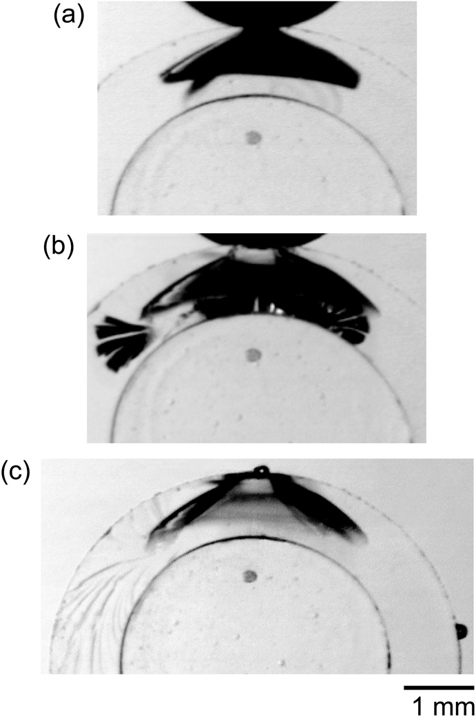
Figure 3 shows a sequence of video clips of a curved surface (ro = 5 mm and ri = 4 mm) cyclically loaded with a WC sphere (r = 1.6 mm) at Pm = 200 N, in water. Outer cone and radial cracks formed at the first cycle and they quickly reached a steady state stage [Fig. 3(a)]. At ~5,400 cycles the radial cracks intersected with the outer cone cracks (through-thickness failure). External water thus gained access to the bottom surface radial cracks. With the assistance of hydraulic pumping, the radial cracks quickly broke out from the outer cone shielding [Fig. 3(b)], surged outward to the outer circumference in the shoulder areas and downward to the margins of the hemi-cylindrical structure within several hundred cycles [Fig. 3(c)] (catastrophic failure).
Figure 3.
In-situ observation of crack evolution in a curved quartz glass/polymer bilayer (glass inner radius ri = 4 mm and thickness d = 1 mm), cyclically indented with a tungsten carbide sphere of radius r = 1.6 mm at Pm = 200 N, in water. (a) Initiation of outer cone and radial cracks at n = 1, (b) propagation of bottom surface radial cracks at n = 5.4 × 10³, and (c) catastrophic failure from bottom surface radial cracks at n = 5.9 × 10³.
The main difference between fatigue of the flat and curved layers was propagation of the radial cracks to the external circumference and the margins of the hemi-cylinder. In fatigue of the flat layers, radial cracks remained subsurface at loads Pm < 450 N.[3]
B. Damage maps
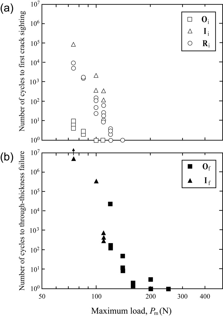
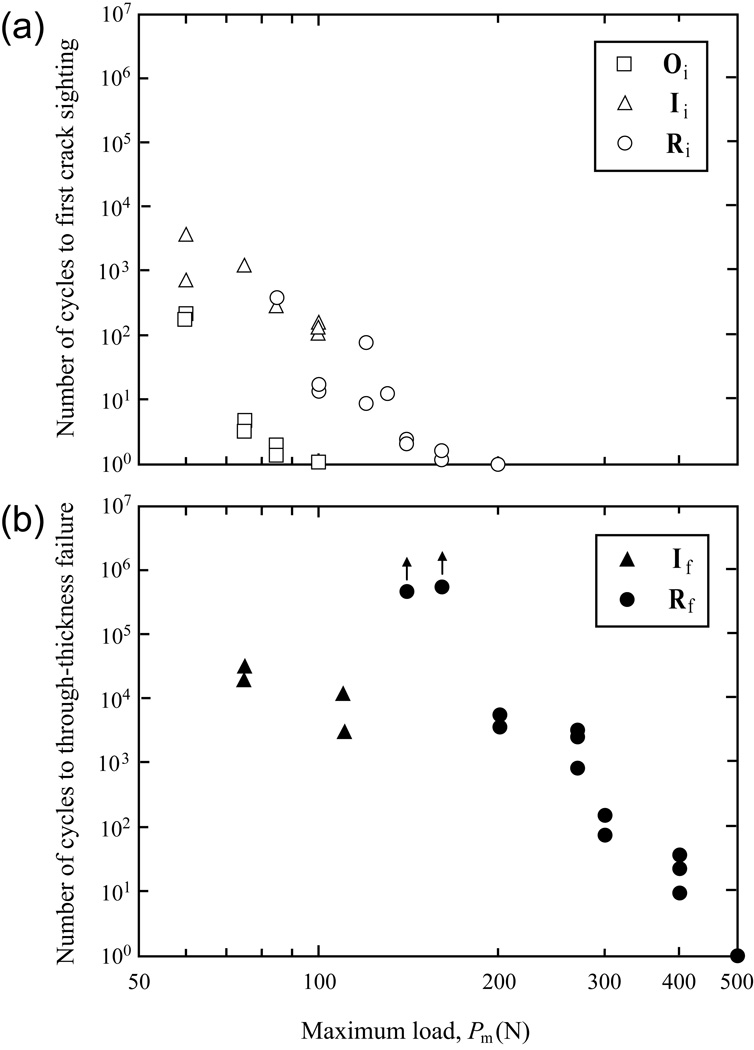
Initiation of the cracks and failure of the layered systems were recorded as a function of the number of cycles for the prescribed fatigue loads. Figures 4 and 5 compare crack evolution data for quartz glass on compliant substrate with flat and curved geometries under fatigue loading in water. Data points are individual measurement of initiation and failure conditions for each crack type. We designate that Oi, Ii, and Ri for the initiation of outer, inner and radial cracks respectively, while Of, If, and Rf for through-thickness failure from outer, inner and radial cracks.
Figure 4.
(a) Crack initiation map and (b) failure map for flat quartz glass on polymer bilayers subject to cyclic indentation with a tungsten carbide sphere of radius r = 1.6 mm, in water. Glass layer thickness d = 1 mm. Oi and Ii indicate outer and inner cone crack initiation respectively, Ri indicates radial crack initiation. Of and If indicate outer and inner cone failures respectively. Arrow in (b) indicates run out.
Figure 5.
(a) Crack initiation map and (b) failure map for curved quartz glass on polymer bilayers subject to cyclic indentation with a tungsten carbide sphere of radius r = 1.6 mm, in water. Glass layer thickness d = 1 mm and inner radius ri = 4 mm. Oi and Ii indicate outer and inner cone crack initiation respectively, while Ri indicates radial crack initiation. If indicates inner cone failure, while Rf indicates for radial failure. Arrows in (b) indicate run out.
In fatigue loading of flat bilayers at Pm < 110 N, outer cone cracks formed first, followed by radial and then inner cone cracks [Fig. 4(a)]. Although inner cone cracks formed last, they propagated downward reaching the glass/polymer interface. Unlike the outer cone and radial cracks, inner cones are driven by hydraulic pumping in addition to SCG.[12] Therefore, inner cone cracks were the dominant mode of failure at loads Pm < 110 N [Fig. 4(b)]. When Pm ≥ 120 N, outer cone and radial cracks formed simultaneously at the first loading cycle. Subsequently, outer cone cracks propagated downward to intersect with the glass/polymer interface within ~102 cycles. Radial cracks, although formed at the first loading cycle, rarely merged to the top, occlusal surface unless Pm > 450 N.[3] The through layer thickness fracture is mainly due to the cone cracks, i.e. at high loads outer cone fracture, and low loads inner cone fracture [Fig. 4(b)]. Radial cracks, clinically referred to as bulk fracture, can form at relatively low loads, but do not propagate through the entire glass layer in these flat layer systems.
Figure 5 shows cracks initiation and failure conditions in fatigue loading of hemi-cylindrical glass shells supported by compliant substrates. Radial cracks were initiated at relatively higher loads compared to the flat bilayer system and propagated at a steady pace until intersection with the outer cones. From this point on, the radial cracks propagated rapidly (with the help of hydraulic pumping) to the external surfaces in the shoulder and margin areas of the curved structures [Fig. 3(b) and (c)]. When Pm < 110 N, outer cones formed first, followed by inner cone and/or radial cracks [Fig. 5(a)]. However, it was always the inner cone cracks that penetrated to the inner circumference of hemi-cylindrical shells, leading to through-thickness failure [Fig. 5(b)]. For 110 N < Pm < 200 N, outer cone formed first, followed by radial cracks. Interestingly, it took over 1 million cycles for radial cracks to extend upward and intersect with outer cone cracks. For Pm ≥ 200 N, radial cracks formed at the first loading cycle and extended continuously until reaching the margin areas, resulting in catastrophic failure of the curved structures [Fig. 5(b)].
IV. DISCUSSION
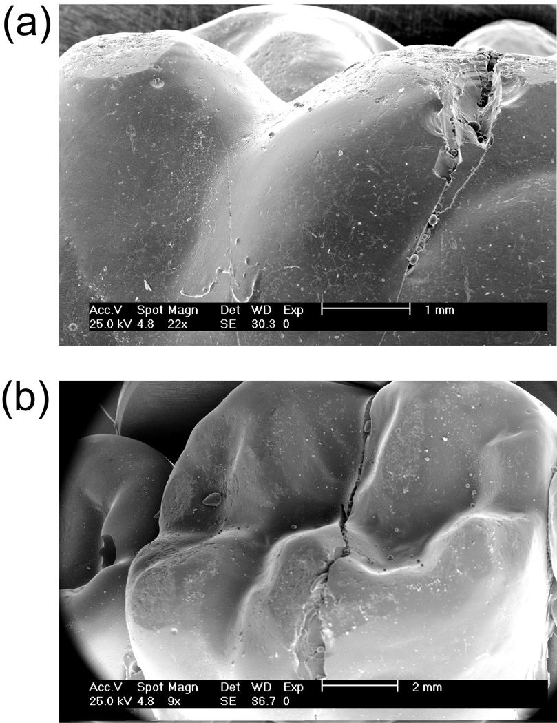
The present study has demonstrated competing damage modes in curved brittle layers subject to concentrated cyclic loading in liquid environments. Two failure modes have been identified: 1) for Pm ≤ 110 N, the top, occlusal surface inner cone cracks penetrating downward and reaching the glass/polymer interface, resulting in chipping/delamination of the glass prostheses; and 2) for Pm ≥ 110 N, the bottom, cementation surface radial cracks propagating upward and sideward and eventually intersecting with the outer cone cracks, resulting in through-thickness fracture. In addition, when Pm ≥ 200 N, the radial cracks, once intersecting with the outer cones, are able to break out from the outer cone shielding, propagate rapidly outward to the external circumference in the shoulder regions and downward to the margins of the hemi-cylindrical shells, resulting in catastrophic failure. This type of catastrophic bulk fracture is often observed in veneered alumina and monolithic glass-ceramic crowns fractured in vivo (Fig. 6).[15] The phenomenon of radial cracks surging to specimen margins was not observed in fatigue loading of flat layer structures, which highlights the important role of surface curvature in the fracture behavior.
Figure 6.
A clinically fractured Cerestore upper right first molar crown following 19 years of intraoral service, showing that fracture initiated within the occlusal contact area and extended to the gingival margin in (a) lingual view and (b) occlusal view. SEM images were supplied by Susanne Scherrer. Note: the damage patterns are similar in clinical crown and curved glass bilayer system.
Previously, it has been reported that bottom radial cracks can extend to the margins of glass domes supported by compliant substrates under single-cycle loading in dry environments.[4, 5] However, the applied load required for such events was ~850 N. Here we demonstrate that under cyclic loading in water, radial cracks can propagate to the margins of brittle curved structures at much lower loads (~200 N), which is well in the range of the nominal biting force (35 – 350 N[14]). This is because once the radial cracks intersect with the outer cones, external water gains access to the subsurface radial cracks. Under cyclic loading, the entrapped water is pumped to the crack front. This hydraulic pumping combined with a greater spatial range of tensile stresses in the curved surfaces relative to the flat structures results in rapid propagation of radial cracks to the margins of the curved structures.
The present study revealed that the critical load Pm for the onset of bottom surface radial crack under single-cycle loading is 200 N for curved structure of this geometry and 120 N for a comparable flat system. The relatively higher critical load for the onset of the radial cracks in the curved structure compared to the flat systems was also observed by Qasim and co-workers.[5] This is because the curvature diminishes the undersurface tensile stress immediately below the contact, which prevents the onset of the bottom radial cracks. However, once the radial cracks form, they can abruptly accelerate toward the margins at the hemi-cylinder base.
The development of near-contact cone cracks in hemi-cylindrical structures in relation to flat specimens deserves elaboration. Our experiments showed that, under a prescribed fatigue load Pm = 75 N, inner cone cracks were first sighted at ~104 cycles in flat specimens [Fig. 4(a)] and ~103 cycles in curved structures [Fig. 5(a)]. Further, the number of cycles required to propagate these inner cone cracks through the glass layer (through-thickness failure) was >106 cycles for flat specimens [Fig. 4(b)] and ~2×10⁴ cycles for curved structures [Fig. 5(b)]. The critical load for the onset of top surface cone cracks in both flat and curved structures, taken from the theory of Hertzian elastic contact, is[16]
| (1) |
where T is the toughness of the brittle material and A is a dimensionless constant. The quantities re and Ee are the effective contact radius and modulus respectively, and can be expressed as[16]
| (2a) |
| (2b) |
where r and rs are the radius of the indenter and specimen surface, and E and Es are the modulus of the intender and brittle material in Fig. 1(b). Since we use the same indenter material (tungsten carbide) and brittle layer (quartz glass) for both flat and curved specimens, the effective moduli in the two cases are identical. However, the effective contact radius for ball on flat layer arrangement is re ≈ 1.6 mm (rs → ∞, 1/rs → 0). The effective contact radius for ball on hemi-cylindrical system is re ≈ 1.2 mm in the direction of the axis of the circle (rs = 5 mm) and re ≈ 1.6 mm in the direction of the axis of the cylinder (rs → ∞). The smaller contact radius effectively reduces the critical load (by ~30% in the current study) for the onset of cone cracks in the direction of the axis of the circle in the hemi-cylindrical structures compared to flat specimens. Thus, for a prescribed fatigue load, the higher indentation stresses in the curved specimens initiate and propagate cone cracks more effectively relative to flat ones. As a result, inner cone cracks formed earlier and propagated all the way through the layer thickness at a much lower number of cycles in the hemi-cylindrical specimens relative to flat structures (Figs. 4 and 5).
We have conducted a fatigue indentation study on a model curved bilayer system―1 mm thick quartz glass of prescribed curvature on a compliant substrate. Compared to flat layered structures, cone cracks in the curved structures form at lower loads and propagate faster, leading to through-thickness failure with less cycles. Flexural radial cracks form at higher loads in the curved specimens, but, once formed, radial cracks are less stable and can rapidly extend to the specimen margins, resulting in catastrophic failure. Such a system has implications concerning the response to Hertzian contact of brittle layer systems for a variety of applications, most notably dental crowns.
Finally, we acknowledge that in the current experiment, we used WC indenter, which is much harder than enamel. The question arises: how the choices of indenter material influence the mechanics? A recent study has shown that the critical loads and number of cycles to penetrate an occlusal surface cone crack through a glass layer is insensitive to the indenter material (WC or glass).[17] The choice of a hard WC indenter is simply to enable multiple testing without the need for test-by-test replacement of the indenter.
ACKNOWLEDGEMENTS
The authors gratefully acknowledge useful discussions with Dr. Brian R. Lawn. This investigation was supported in part by Research Grant 1R01 DE017925 (PI. Zhang) from the United States National Institute of Dental 6 Craniofacial Research, National Institutes of Health and Research Grant CMMI-0758530 (PI. Zhang) from the United States Division of Civil, Mechanical 6 Manufacturing Innovation, National Science Foundation and the Korea Research Foundation Grant (KRF-2006-005-J02701) and Changwon National University.
REFERENCES
- 1.Lawn BR, Bhowmick S, Bush MB, Qasim T, Rekow ED, Zhang Y. Journal of the American Ceramic Society. 2007;90:1671. [Google Scholar]
- 2.Lawn BR, Deng Y, Miranda P, Pajares A, Chai H, Kim DK. Journal of Materials Research. 2002;17:3019. [Google Scholar]
- 3.Zhang Y, Kim JW, Bhowmick S, Thompson VP, Rekow ED. Journal of biomedical materials research. 2008 doi: 10.1002/jbm.b.31100. [DOI] [PMC free article] [PubMed] [Google Scholar]
- 4.Kim JW, Bhowmick S, Chai H, Lawn BR. Journal of biomedical materials research. 2007;81:305. doi: 10.1002/jbm.b.30666. [DOI] [PubMed] [Google Scholar]
- 5.Qasim T, Bush MB, Hu X, Lawn BR. Journal of biomedical materials research. 2005;73:179. doi: 10.1002/jbm.b.30188. [DOI] [PubMed] [Google Scholar]
- 6.Rudas M, Qasim T, Bush MB, Lawn BR. Journal of Materials Research. 2005;20:2812. [Google Scholar]
- 7.Ford C, Qasim T, Bush MB, Hu X, Shah MM, Saxena VP, Lawn BR. Journal of biomedical materials research. 2007 doi: 10.1002/jbm.b.30911. [DOI] [PubMed] [Google Scholar]
- 8.Qasim T, Ford C, Bush MB, Hu X, Lawn BR. Journal of biomedical materials research. 2006;76:334. doi: 10.1002/jbm.b.30373. [DOI] [PubMed] [Google Scholar]
- 9.Qasim T, Ford C, Bush MB, Hu X, Malament KA, Lawn BR. Journal of biomedical materials research. 2007;80:78. doi: 10.1002/jbm.b.30571. [DOI] [PubMed] [Google Scholar]
- 10.Bhowmick S, Zhang Y, Lawn BR. Journal of Materials Research. 2005;20:2792. [Google Scholar]
- 11.Zhang Y, Lawn B. Bioceramics 17. 2005;17:697. [Google Scholar]
- 12.Zhang Y, Song JK, Lawn BR. Journal of biomedical materials research. 2005;73:186. doi: 10.1002/jbm.b.30195. [DOI] [PubMed] [Google Scholar]
- 13.Zhang Y, Bhowmick S, Lawn BR. Journal of Materials Research. 2005;20:2021. [Google Scholar]
- 14.Kelly JR. The Journal of Prosthetic Dentistry. 1999;81:652. doi: 10.1016/s0022-3913(99)70103-4. [DOI] [PubMed] [Google Scholar]
- 15.Kim B, Zhang Y, Pines M, Thompson VP. J Dent Res. 2007;86:142. doi: 10.1177/154405910708600207. [DOI] [PubMed] [Google Scholar]
- 16.Rhee Y-W, Kim H-W, Deng Y, Lawn BR. Journal of the American Ceramic Society. 2001;84:561. [Google Scholar]
- 17.Bhowmick S, Melendez-Martinez JJ, Hermann I, Zhang Y, Lawn BR. Journal of biomedical materials research. 2007;82:253. doi: 10.1002/jbm.b.30728. [DOI] [PubMed] [Google Scholar]


