Abstract
Objectives/Hypothesis
We have previously described a novel, automated, non-rigid, model-based method for determining the intrascalar position of cochlear implant (CI) electrodes arrays within human temporal bones using clinically available, flat-panel volume computed tomography (fpVCT). We sought to validate this method by correlating results with anatomic microdissection of CI arrays in cadaveric bones.
Study Design
Basic science.
Methods
Seven adult cadaveric temporal bones were imaged using fpVCT before and after electrode insertion. Using a statistical model of intra-cochlear anatomy an active shape model optimization approach was then used to identify the scala tympani and vestibuli on the pre-intervention fpVCT. The array position was estimated by identifying its midline on the post-intervention scan and superimposing it onto the pre-intervention images using rigid registration. Specimens were then microdissected to demonstrate the actual array position.
Results
Using microdissection as the standard for ascertaining electrode position, the automatic identifications of the basilar membrane coupled with post-intervention fpVCT for electrode position identification accurately depicted the array location in all seven bones. In four specimens, the array remained within the scala tympani; in three the basilar membrane was breached.
Conclusions
We have anatomically validated the automated method for predicting the intrascalar location of CI arrays using CT. Using this algorithm and pre- and post-intervention CT, rapid feedback regarding implant location and expected audiological outcomes could be obtained in clinical settings.
Keywords: Cochlear implant, computed tomography, registration
Introduction
Since the introduction of cochlear implantation in the 1970s, the technique has progressed to become the standard of care for restoration of hearing in adults with profound sensorineural hearing loss. Continued refinements in implant devices, sound processing strategies, and surgical techniques have resulted in a steady improvement in clinical performance. Despite this trend toward increasing sophistication, individual hearing outcomes remain quite variable, and ongoing research has attempted to identify factors that contribute to a successful result, which ultimately is defined by a functional level of hearing that improves the quality of life of the deaf patient. Of those factors affecting the degree of hearing restoration after cochlear implantation, many are intrinsic to the patient and unalterable by the treating team. These include but are not limited to duration of deafness and length of CI use1,2, level of pre-implant speech recognition2, and pre/postlingual status3. Conversely, variables relating to the management of CI patients, such as electrode coupling4 and speech processing strategies5, are within the realm of clinician control and also affect post-operative speech recognition.
A number of recent studies have identified factors relating to the surgical procedure that are important determinants of audiological outcome. Ideally, the electrode array should be inserted to an adequate depth, solely within the scala tympani (ST) and near the modiolus, with minimal trauma to the basilar membrane, spiral lamina, Reissner’s membrane, and other intracochlear structures. The atraumatic perimodiolar ST insertion is intended to place the electrode contacts in closest, safest possible proximity to the spiral ganglion cells without damaging vital cochlear components; evidence from animal models has suggested that this location results in decreased stimulation thresholds and increased dynamic range6,7.
In practice, however, suboptimal insertions may be the rule rather than the exception. Histologic studies of temporal bones from cochlear implant patients have demonstrated frequent insertional trauma to structural and neural elements, although fortunately in most cases the spiral ganglion cell counts were not affected.8–11 Benchtop studies using test insertions performed in human temporal bone specimens have echoed these findings, demonstrating intracochlear trauma12 and frequent migration of the array to the lateral wall or from the ST to scala vestibuli (SV). In an in vivo analysis of adult CI patients using post-operative three-dimensional digital radiography (rotational tomography), Aschendorff et al reported that 10/22 of arrays were completely within the scala vestibuli and 6/22 dislocated from ST to SV at approximately 180 degrees.13
Several groups have recently described a positive relationship between ST electrode placement and post-operative speech perception. Finley et al14 and Skinner et al15 used coregistration of pre- and postoperative patient CT scans with micro CT and orthogonal-plane fluorescence optical sectioning (OPFOS) of a cochlea from a body donor to estimate the depth of insertion and intracochlear location of the electrode array. In both studies, the number of electrodes within the SV inversely correlated with Consonant/Nucleus/Consonant (CNC) test scores. Finley et al. reported that 83% of variance in CNC scores could be accounted for using a linear regression model with scalar position, patient age, and total SV electrode count as variables.14 In a later study, Aschendorff et al used post-operative rotational tomography to correlate speech perception with ST insertion.16
Some authors have identified a positive correlation between insertion depth and speech perception17, with histologic studies on temporal bone specimens failing to show undue trauma from insertion of the array to the apex of the cochlea18. Conversely, others have reported a negative correlation between audiological test results and insertion depth19, with deep insertions found to be associated with increased number of electrodes in the scala vestibuli, diminished pitch discrimination, decreased basal stimulation14, and pitch confusion at apical contacts.20
Numerous modalities have been used to visualize electrode array placement in temporal bones. In vitro experiments allow high resolution, accurate analysis of electrode placement, using histologic techniques such as resin embedding and sectioning,18, 21–22 microdissection,23 and high-resolution radiologic techniques such as micro CT.24 These techniques are unavailable for studies of CI location in actual patient temporal bones, aside from specimens obtained at autopsy. As such, other radiologic techniques such as rotational tomography13,16 or conventional CT scanning are required. Clinical CT has the advantage of reasonable cost, safety, and accessibility, but suffers from artifact produced by the metal electrode contacts as well as potential error in locating the array within intracochlear compartments. Multislice CT has been reported to allow identification of electrode location within the cochlear compartments25–26, although others have challenged its accuracy compared to rotational tomography.27
In the current study, we present a novel technique for precise localization of cochlear implant electrodes within human temporal bones using novel software algorithms that require only a standard clinical pre-operative CT for locating the scalae and a post-operative CT of at least low-dose quality to locate the electrode position, e.g., images from a clinically available portable, flat-panel volume computed tomography (fpVCT) scanner. The accuracy of the three dimensional reconstructions produced with this software were verified using anatomic microdissection, demonstrating that this method is highly precise and poised for clinical application.
Methods
Seven human cadaveric temporal bones were obtained from the anatomy laboratory at Vanderbilt University School of Medicine. The donor cadavers had previously been embalmed and stored in the standard fashion for use in dissection. The cochlea were harvested from each cadaver using a bone saw and kept in a deep freezer prior to electrode insertion and microdissection.
Prior to electrode insertion, an fpVCT scan was obtained using a clinically-available machine [Xoran xCAT ENT, Xoran Technologies, Ann Arbor, MI]. The imaging parameters were as follows: tube voltage = 120KvP, tube current = 7mA, pulse length = 15ms, number of frames = 820, scan time = 60s, total filtration = 0.38 mm Cu + 1.6 mm Al + Al bow tie. Whole heads induce much greater signal loss in fpVCT than the temporal bone specimens used in this study. Thus, the fpVCT were of high enough quality in these experiments, but a pre-operative conventional CT would be necessary in clinical application. The temporal bones were then placed in rigid frames and a standard size 1mm rough diamond burr was used with an otologic drill [Anspach, Palm Beach Gardens, FL] and operating microscope to create a cochleostomy just anterior and inferior to the round window. The site was gently irrigated and a modiolar-hugging electrode [Freedom Advance, Cochlear Corporation, Sydney, Australia] was inserted using advance off stylet technique to the double marker. On certain bones a slightly rougher technique was used to insert the electrodes in order to attempt to increase the chance of breaching the basilar membrane. Epoxy glue was then used to secure the external portion of the electrode to the temporal bone surface approximately 5mm from the cochleostomy site, after which the excess electrode was clipped using wire cutters. A second fpVCT scan was then obtained using the Xoran xCAT. The temporal bones were then carefully packed in a sealed, cushioned, chilled container and shipped overnight to the Otology Laboratory at the University of Texas Southwestern Medical Center where staining and microdissection were performed to verify electrode placement.
Microdissection of temporal bone specimens was performed following a previously described protocol.23 Briefly, osmium tetroxide was used to stain the inner ear tissues, after which the cochlea was carefully dissected and the otic capsule bone thinned using an operating microscope and diamond drill. After removal of bone overlying the scala vestibuli, high resolution photographs were obtained before and after removing the osseous lamina and basilar membrane, which allowed direct visualization into the ST.
Blinded to the results of the microdissection, three-dimensional representations of temporal bone anatomy, including the ST and SV, were created using previously described automated algorithms.28–30 To locate the ST and SV, a statistical model of these structures was creating using micro CTs of six cadaveric cochleae as a training set. Using what is known as an active shape model algorithm in the medical imaging literature,33 this model can be fit to a cochlea in a patient CT, while being constrained to maintain a shape that is representative of the shapes in the training set. Thus, the ST and SV are aligned with the visible edges of the cochlea in the CT, while the statistical model constrains the location of the basilar membrane to be the location we would expect it to be, given the anatomical shape information we have from the training set. Identification of anatomical structures must be performed in the pre-operative, rather than postoperative, CT to avoid inaccuracies introduced by artifact from the electrode array. Next, the centerline of the electrode was identified in the post-insertion fpVCT. This is performed automatically by: (1) Identifying the voxels occupied by the electrode using thresholding and noise reduction techniques; and (2) Identifying the centerline of these voxels using voxel thinning techniques.32 These results are then rigidly registered to the pre-intervention CT, so that the electrode, ST, and SV can be graphically displayed in the same spaceOn a reasonably powered desktop PC, this entire process takes approximately six minutes. These reconstructions were then correlated with microdissections.
Results
In four temporal bone specimens, the software reconstructions revealed that the electrode arrays were located entirely within the ST. For each of these specimens, microdissection verified these findings. Representative two-dimensional screenshots of software reconstructions and corresponding photographs of dissected specimens are shown in Figure 1 for these four bones.
Figure 1.
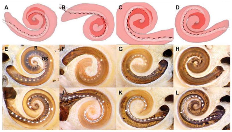
Electrode arrays entirely within scala tympani (ST). In four temporal bones, the arrays remained within the ST. Representative screen captures for each of the reconstructions are illustrated in A–D. The ST is shaded translucent red, allowing the array to be seen inside (the scala vestibuli [SV] is not shown). The darker red area outlines the path of the apical turn. E–H are corresponding photographs of each cochlea after microdissection. In each case, the array can be seen through the basilar membrane (B) and osseous lamina (OS) to be resting entirely within the ST. In these specimens, the apical cochlear turn has been removed to provide an unobstructed view of the basal turn. I–L depict the same specimens after removal of the osseous lamina and basilar membrane, allowing direct visualization of the arrays in the ST.
In three specimens, the electrode array crossed the basilar membrane into the SV. Figure 2 illustrates a specimen in which the software predicted that the array entered the ST through the cochleostomy but crossed the basilar membrane at approximately 170 degrees to enter the SV, which was confirmed upon microdissection. Additionally, both microdissection and image reconstruction identified a small fracture in the osseous lamina of the hook region likely due to insertional trauma. Figure 3 shows another cochlea in which the electrode crossed the basilar membrane at 180 degrees, traveling from scala tympani to scala vestibuli. Again, this was accurately modeled by the software.
Figure 2.
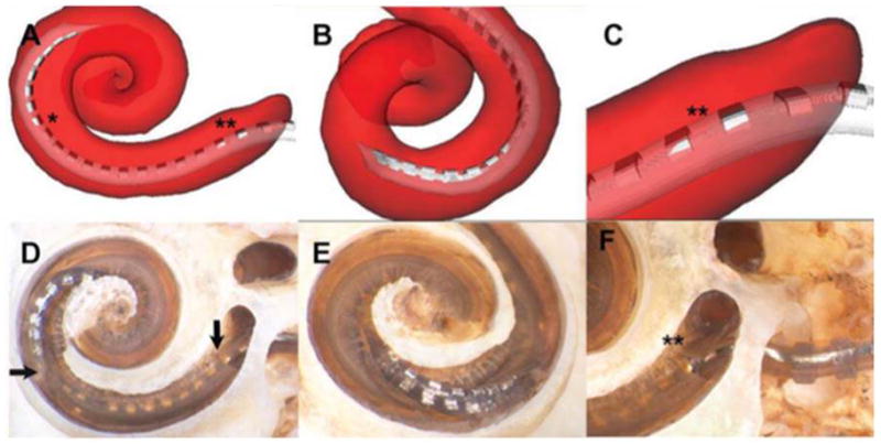
Insertional trauma with array crossing basilar membrane at 170°. In this specimen, the image reconstruction shows that the array initially occupied the scala tympani (ST) after insertion through the cochleostomy but crossed the basilar membrane at approximately 170° to enter the scala vestibuli (SV) (asterisk on A). Microdissection verified this finding, illustrating a breach in the basilar membrane (horizontal arrow, D), distal to which the apical electrode contacts are inside the SV. B and E depict a rotated view of the point of basilar membrane crossing. The reconstruction also suggested subtle insertional trauma in the area of the hook (double asterisk, A and C); this was also verified upon microdissection, with a small fracture of the osseous lamina shown in D (vertical arrow) and F (double asterisk).
Figure 3.
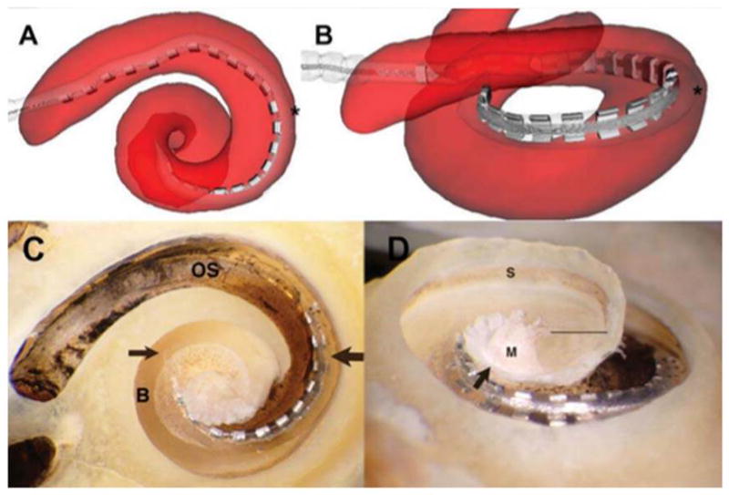
Array crossing basilar membrane at 180°. The array originates in the scala tympani (ST) but crosses the basilar membrane into the scala vestibuli (SV) at approximately 180° (asterisk in A and B). The accuracy of the reconstruction is again verified by microdissection; in C, the point of transition between scalae is indicated by the thick arrow, with the thin arrow showing the tip of the array situated above the basilar membrane. “OS” indicates the osseous lamina of the basal turn, and “B” indicates the surface of the basilar membrane near the tip of the array. B and C give an inferiorly rotated view of the electrode path; in D, the specimen is tilted to show the array lying in the SV, above the basilar membrane; the straight line indicates the cut edge of the basilar membrane apical to the area occupied by the array(below the line is the ST of the lower apical turn). The arrow indicates the cut edge of the bony septum separating the SV of the middleturn from the ST of the apical turn. “S” indicates the stria vascularis immediately above the attachment zone of the basilar membrane; “M”labels the modiolus.
In a final cochlea, the electrode array followed a path primarily within the ST but displacing the basilar membrane superiorly in the area of its attachment to the lateral wall (see Figure 4). The corresponding reconstruction is more difficult to assess regarding its agreement with the microdissection due to traumatic repositioning of the basilar membrane, but is still accurate in predicting electrode location.
Figure 4.
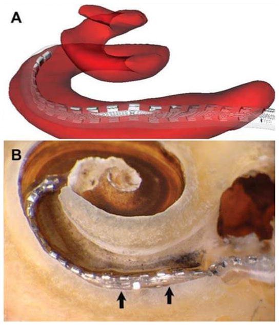
Traumatic insertion with displacement of basilar membrane. As indicated in A, the image reconstruction suggests that the array straddles the scala tympani (ST) and scala vestibuli (SV). Microdissection revealed a traumatic insertion with electrode buckling in the area of the cochleostomy (B), as well as displacement of the basilar membrane above the level of its normal attachment with the lateral bony wall (arrows). The array thus sits below the basilar membrane but in approximately the region that the membrane would normally occupy, with the apical tip situated more superiorly within the SV.
Discussion
Using anatomical microdissection of temporal bones previously implanted with electrode arrays, this study was successful in validating the accuracy of novel algorithms for predicting intracochlear array position based upon pre- and post-intervention CT. Validation of this software is a crucial step prior to clinical application.
Previous studies have used a variety of imaging modalities combined with rigid registration techniques to assess implant location within the ST and SV.13–16,24–26 Compared to conventional rigid registration, our non-rigid method has the advantage of accounting for non-linear variation in individual cochlear shapes. Rigid registration assumes similar proportions exist between patients, and is a relatively simple method of aligning structures by translating, rotating, stretching, and skewing the atlas to fit unknown anatomy. This method can work well if the anatomy is very similar, but fails if differences between patients are substantial. For example, consider registering a square to a circle. Even with translation (moving side to side or up and down), rotation, stretching, or skewing (making the square a parallelogram), the result is still a square superimposed on a circle. Conversely, in non-rigid techniques, the model of the structure can be warped in more complex ways, allowing one part of the atlas to be stretched more than another if necessary. Using the previous analogy, this would allow one to bend the corners of the square to better fit the circle. Furthermore, whereas previous studies15 have used anatomical reference atlases based on a single cadaver temporal bone, our model of intra-cochlear anatomy was created using high-resolution micro-CT scans from six adult cochlea, creating a more accurate representation of true anatomical variations.
The results of image reconstruction correlated with microdissection for each of the seven temporal bones studied. For the specimens illustrated in Figures 2 and 3, the precise location at which the electrode breached the basilar membrane was accurately predicted by the software. A more complex situation occurred in the temporal bone shown in Figure 4, where microdissection revealed a traumatic insertion with upward displacement of the basilar membrane at its attachment with the lateral wall. On the three-dimensional reconstruction, the electrode has the appearance of straddling the basilar membrane. From the histological assessment we see that this occurs due to upward deviation of the basilar membrane. Extrapolating from this specimen, we conclude that the most reasonable interpretation of a reconstruction with the appearance of an electrode running through the basilar membrane is displacement of soft tissue.
Although the software-based reconstructions are accurate and effective in predicting electrode array location, as evidenced by the results of the microdissections, they do have subtle limitations. A careful analysis of Figure 1 reveals that the actual electrode arrays were found to penetrate more apically (Figure 1, A–D) than predicted by the software (Figure 1, I–L). In addition, the array in Figure 4L appears perimodiolar in the anatomic specimen, yet swings out to contact the lateral wall of the scala tympani at 270 degrees in the computer model. These discrepancies may be related to the detection algorithm used in the registration process; however, these issues do not compromise the ability of the software to predict the presence and location of basilar membrane penetration, which is the most clinically-relevant goal of this project.
Given recent insights into the relationship between intracochlear electrode position and audiological outcomes, specifically the association between preferential scala tympani insertion and improved hearing14–16, the need for safe and accurate methods for elucidating electrode array position within cochlear implant recipients is significant. One approach that is feasible given recent technological advances involves obtaining a portable fpVCT scan immediately after cochlear implant electrode insertion, ideally in the operating room. The radiation dose of the scan used in this study is 0.35mSv, ¼ that of a conventional head CT and approximately equal to one month of background radiation exposure.31 Applying non-rigid registration software, these images could then be used to create an accurate model of electrode placement within intracochlear compartments. A sample output showing the correlation of the reconstruction with CT images is shown in Figure 5.
Figure 5.
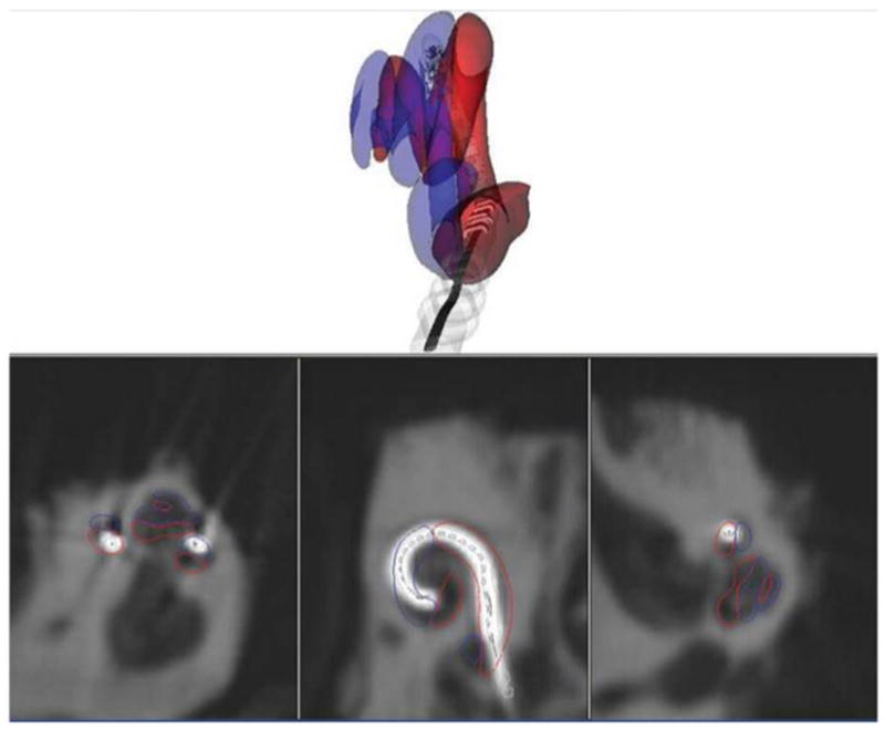
Sample screenshot showing real-time correlation with flat-panel volume computed tomography (fpVCT images). This is the same specimen as depicted in Fig. 3, with the electrode array traveling from the scala tympani (red outline) to scala vestibuli (blue outline) at 180°. This screenshot includes fpVCT images in all three planes, demonstrating how compartment volumes are calculated from imaging data.
Accurate information regarding electrode placement within the cochlea is potentially useful in several ways. First, it would enable immediate prediction of hearing outcome and allow an audiologist to program the implant based upon precise knowledge of electrode location. Additionally, these results would provide feedback to surgeons for assessment of insertional techniques and electrode designs in order to hone their skills and assess approach to future procedures. Finally, routine use of such techniques could create a wealth of accurate data for use in ongoing research.
Conclusion
This study used anatomical microdissection to validate a novel, non-rigid, deformable model technique for predicting the precise intrascalar location of cochlear implant arrays using clinically-available CT before and after insertion. Numerous prior studies have suggested that preferential scala tympani electrode position is associated with improved audiological outcomes after cochlear implantation. Our technique of non-rigid registration provides advantages over techniques used in prior studies due to its ability to perform complex transformations of individual cochlea to a standard atlas. With validation of this technique, we envision that patients could undergo portable computed tomography of the temporal bones in the operating room after cochlear implantation, and this data could be immediately used to create an accurate model of electrode placement, which in turn could be useful in predicting audiological outcomes and facilitating precise electrode programming.
Acknowledgments
The authors wish to acknowledge Daniel Schurzig and Ramya Balachandran for assistance with performing computed tomography.
This work was supported by Award Number R01DC008408 (R.F.L.) from the National Institute on Deafness and Other Communication Disorders, as well as Award Numbers R01EB006193 andF31DC009791 (B.D.). The content is solely the responsibility of the authors and does not necessarily represent the official views of the National Institute on Deafness and Other Communication Disorders or the National Institutes of Health. Work in this project was also sup-ported in part by a research contract with Cochlear Corporation, which provided electrodes and financial support.
Footnotes
Presented at the Triological Society Annual Meeting, Las Vegas, NV, April 30, 2010.
References
- 1.Blamey P, Arndt P, Bergeron F, et al. Factors affecting auditory performance of postlinguistically deaf adults using cochlear implants. Audiol Neurotol. 1996;1:293–306. doi: 10.1159/000259212. [DOI] [PubMed] [Google Scholar]
- 2.Rubinstein JT, Parkinson WS, Tyler RS, et al. Residual speech recognition and cochlear implant performance: effects of implantation criteria. Am J Otol. 1999;20:445–52. [PubMed] [Google Scholar]
- 3.Tong YC, Busby PA, Clark GM. Perceptual studies on cochlear implant patients with early onset of profound hearing impairment prior to normal development of auditory, speech, and language skills. J Acoust Soc Am. 1988;84:951–962. doi: 10.1121/1.396664. [DOI] [PubMed] [Google Scholar]
- 4.Pfingst BE, Franck KH, Xu L, et al. Effects of electrode configuration and place of stimulation on speech perception with cochlear prostheses. J Assoc Res Otolaryngol. 2001;2:87–103. doi: 10.1007/s101620010065. [DOI] [PMC free article] [PubMed] [Google Scholar]
- 5.Skinner MW, Holden LK, Whitford LA, et al. Speech recognition with the 24 SPEAK, ACE, and CIS speech coding strategies in newly implanted adults. Ear Hear. 2002;23:207–23. doi: 10.1097/00003446-200206000-00005. [DOI] [PubMed] [Google Scholar]
- 6.Shepherd RK, Hatsushika S, Clark GM. Electrical stimulation of the auditory nerve: the effect of electrode position on neural excitation. Hear Res. 1993;66:108–20. doi: 10.1016/0378-5955(93)90265-3. [DOI] [PubMed] [Google Scholar]
- 7.Marsh RR, Yamane H, Potsic WP. Effect of site of stimulation on the guinea pig’s electrically evoked brain stem response. Otolaryngol Head Neck Surg. 1981;89:125–30. doi: 10.1177/019459988108900127. [DOI] [PubMed] [Google Scholar]
- 8.Fayad J, Linthicum FH, Jr, Otto SR, et al. Cochlear implants: histopathologic findings related to performance in 16 human temporal bones. Ann Otol Rhinol Laryngol. 1991;100(10):807–11. doi: 10.1177/000348949110001004. [DOI] [PubMed] [Google Scholar]
- 9.Linthicum FH, Jr, Fayad J, Otto SR, et al. Cochlear implant histopathology. Am J Otol. 1991;12:245–311. [PubMed] [Google Scholar]
- 10.Nadol JB, Jr, Shiao JY, Burgess BJ, et al. Histopathology of cochlear implants in humans. Ann Otol Rhinol Laryngol. 2001 Sep;110(9):883–91. doi: 10.1177/000348940111000914. [DOI] [PubMed] [Google Scholar]
- 11.Nadol JB, Jr, Ketten DR, Burgess BJ. Otopathology in a case of multichannel cochlear implantation. Laryngoscope. 1994 Mar;104(3 Pt 1):299–303. doi: 10.1288/00005537-199403000-00010. [DOI] [PubMed] [Google Scholar]
- 12.Kennedy DW. Multichannel intracochlear electrodes: mechanism of insertional trauma. Laryngoscope. 1987 Jan;97(1):42–9. doi: 10.1288/00005537-198701000-00011. [DOI] [PubMed] [Google Scholar]
- 13.Aschendorff A, Kubalek R, Turowski B, et al. Quality control after cochlear implant surgery by means of rotational tomography. Otol Neurotol. 2005;26:34–7. doi: 10.1097/00129492-200501000-00007. [DOI] [PubMed] [Google Scholar]
- 14.Finley CC, Holden TA, Holden LK, et al. Role of electrode placement as a contributor to variability in cochlear implant outcomes. Otol Neurotol. 2008;29:920–28. doi: 10.1097/MAO.0b013e318184f492. [DOI] [PMC free article] [PubMed] [Google Scholar]
- 15.Skinner MW, Holden TA, Whiting BR, et al. In vivo estimates of the position of Advanced Bionics electrode arrays in the human cochlea. Ann Otol Rhinol Laryngol. 2007;116(4)(Suppl 197):1–24. [PubMed] [Google Scholar]
- 16.Aschendorff A, Kromeier J, Klenzer T, et al. Quality control after insertion of the Nucleus Contour and Contour Advance electrode in adults. Ear & Hearing. 2007;28:75S–79S. doi: 10.1097/AUD.0b013e318031542e. [DOI] [PubMed] [Google Scholar]
- 17.Yukawa K, Cohen L, Blamey P, et al. Effects of insertion depth of cochlear implant electrodes upon speech perception. Audiol Neurotol. 2004;9:163–72. doi: 10.1159/000077267. [DOI] [PubMed] [Google Scholar]
- 18.Gstoettner W, Plenk H, Jr, Franz P, et al. Cochlear implant deep electrode insertion: extent of insertional trauma. Acta Otolaryngol. 1997 Mar;117(2):274–7. doi: 10.3109/00016489709117786. [DOI] [PubMed] [Google Scholar]
- 19.Skinner M, Holden LK, Holden TA, et al. Factors predictive of open-set word recognition in adults with cochlear implants [poster presentation]. 2007 Conference on Implantable Auditory Prostheses; Lake Tahoe, CA. 2007. [Google Scholar]
- 20.Gani M, Valentini G, Sigrist A, et al. Implications of deep electrode insertion on cochlear implant fitting. J Assoc Res Otolaryngol. 2007;8:69–83. doi: 10.1007/s10162-006-0065-4. [DOI] [PMC free article] [PubMed] [Google Scholar]
- 21.Roland JT, Jr, Fishman AJ, Alexiades G, et al. Electrode to modiolus proximity: a fluoroscopic and histologic analysis. Am J Otol. 2000;21:218–225. doi: 10.1016/s0196-0709(00)80012-5. [DOI] [PubMed] [Google Scholar]
- 22.Roland JT., Jr A model for cochlear implant electrode insertion and force evaluation: results with a new electrode design and insertion technique. Laryngoscope. 2005;115:1325–39. doi: 10.1097/01.mlg.0000167993.05007.35. [DOI] [PubMed] [Google Scholar]
- 23.Wright CG, Roland PS. Temporal bone microdissection for anatomic study of cochlear implant electrodes. Coch Imp Int. 2005;6(4):159–68. doi: 10.1179/cim.2005.6.4.159. [DOI] [PubMed] [Google Scholar]
- 24.Postnov A, Zarowski A, De Clerck N, et al. High resolution micro-CT scanning as an innovatory tool for evaluation of the surgical positioning of cochlear implant electrodes. Acta Otolaryngol. 2006;126:467–74. doi: 10.1080/00016480500437377. [DOI] [PubMed] [Google Scholar]
- 25.van Wermeskerken GJ, Prokop M, van Olphen AF, et al. Intracochlear assessment of electrode position after cochlear implant surgery by means of multislice computer tomography. Eur Arch Otorhinolaryngol. 2007;264:1405–7. doi: 10.1007/s00405-007-0389-7. [DOI] [PubMed] [Google Scholar]
- 26.Verbist BM, Frijns JHM, Geleijns J, et al. Multisection CT as a valuable tool in the postoperative assessment of cochlear implant patients. Am J Neuroradiol. 2005;26:424–9. [PMC free article] [PubMed] [Google Scholar]
- 27.Aschendorff A, Kubalek R, Hochmuth A, et al. Imaging procedures in cochlear implant patients – evaluation of different radiological techniques. Acta Otolaryngol Suppl. 2004;552:46–9. [PubMed] [Google Scholar]
- 28.Noble JH, Warren FM, Labadie RF, et al. Automatic segmentation of the facial nerve and chorda tympani in CT images using spatially dependent feature values. Med Phys. 2008;35(12):5375–84. doi: 10.1118/1.3005479. [DOI] [PMC free article] [PubMed] [Google Scholar]
- 29.Noble JH, Rutherford RB, Labadie RF, Majdani O, Dawant BM. Modeling and segmentation of intracochlear anatomy in conventional CT. Proceedings of the SPIE Conf On Medical Imaging. 2010;7623:762392. [Google Scholar]
- 30.Noble JH, Dawant BM, Warren FM, et al. Automatic identification and 3D rendering of temporal bone anatomy. Otol Neurotol. 2009;30(4):436–42. doi: 10.1097/MAO.0b013e31819e61ed. [DOI] [PMC free article] [PubMed] [Google Scholar]
- 31.need reference
- 32.Bouix S, Siddiqi K, Tannenbaum A. Flux driven automatic centerline extraction. Medical Image Analysis. 2005;9:209–221. doi: 10.1016/j.media.2004.06.026. [DOI] [PubMed] [Google Scholar]
- 33.Cootes TF, Taylor CJ, Cooper DH, Graham J. Active Shape Models—Their Training and Application. Comp Vis And Image Unders. 1995;61(1):39–59. [Google Scholar]


