Abstract
Purpose
To extend the functionality of radiographic/fluoroscopic imaging systems already within standard spine surgery workflow to: 1) provide guidance of surgical device analogous to an external tracking system; and 2) provide intraoperative quality assurance (QA) of the surgical product.
Methods
Using fast, robust 3D-2D registration in combination with 3D models of known components (surgical devices), the 3D pose determination was solved to relate known components to 2D projection images and 3D preoperative CT in near-real-time. Exact and parametric models of the components were used as input to the algorithm to evaluate the effects of model fidelity. The proposed algorithm employs the covariance matrix adaptation evolution strategy (CMA-ES) to maximize gradient correlation (GC) between measured projections and simulated forward projections of components. Geometric accuracy was evaluated in a spine phantom in terms of target registration error at the tool tip (TREx), and angular deviation (TREϕ) from planned trajectory.
Results
Transpedicle surgical devices (probe tool and spine screws) were successfully guided with TREx <2 mm and TREϕ<0.5° given projection views separated by at least >30° (easily accommodated on a mobile C-arm). QA of the surgical product based on 3D-2D registration demonstrated the detection of pedicle screw breach with TREx <1 mm, demonstrating a trend of improved accuracy correlated to the fidelity of the component model employed.
Conclusions
3D-2D registration combined with 3D models of known surgical components provides a novel method for near-real-time guidance and quality assurance using a mobile C-arm without external trackers or fiducial markers. Ongoing work includes determination of optimal views based on component shape and trajectory, improved robustness to anatomical deformation, and expanded preclinical testing in spine and intracranial surgeries.
Keywords: 3D-2D image registration, image-guided surgery, surgical navigation, quality assurance, spine surgery
1. INTRODUCTION AND PURPOSE
Many procedures in neurosurgery and orthopaedic spine surgery, such as pedicle screw placement, require a high degree of geometric accuracy due to the proximity of critical structures.1 In such procedures, identifying the appropriate trajectory to target tissue can challenge even experienced surgeons and meets with an unacceptably high rate of revision surgeries and adverse events. Standard intraoperative x-ray fluoroscopy and radiography provide up-to-date visualization of anatomy and surgical devices, but in a fairly qualitative two-dimensional manner.
The need for accurate 3D guidance has motivated the use of external tracking systems for surgical navigation using select tools, external markers affixed to the tools and patient, and an additional image-to-world registration step. The broad utility of such navigation systems, however, has been somewhat limited by the additional, sometimes cumbersome, workflow imposed on the procedure, requiring preoperative placement of extrinsic fiducials, calibration of individual tools, manual patient registration, and additional intra-operative constraints such as line-of-sight (for optical trackers) or metal interference (for electromagnetic trackers).
This work develops a system that provides 3D guidance and quality assurance (QA) based on a fast, robust 3D-2D registration method combined with 3D models of “known components” (i.e., surgical tools) – referred to as known-component registration (KC-Reg). The method uses 2D x-ray projections acquired within the standard workflow of fluoroscopically guided procedures, exploiting knowledge of component shape and composition to solve for the 3D pose in near-real-time. In principle, the approach amounts to the imaging system itself serving as a “tracker” and the patient as their own “fiducial” and could extend the functionality of intraoperative imaging that already exists within the standard surgical arsenal while absolving the workflow bottlenecks associated with conventional tracking systems. The method further allows more quantitative QA of the surgical product by measuring device placement relative to preoperative images and surgical plan.
2. METHODS
2.1 Known Components
Prior knowledge of surgical tools is available in many surgical applications, e.g., fixation hardware or joint prostheses, and is applicable to interventional tasks where such devices are placed through use of guide wires or needles. Utilizing prior knowledge of these known components has been proposed in the context of statistical 3D image reconstruction, where tool poses computed from an orbital acquisition were used to reduce metal artifacts in the image.2 Same principles can be applied to the context of model-based registration by modeling these components in different forms.
Two known components relevant to the clinical task in transpedicle spine surgery were the probe tool (e.g., a Jamshidi needle or awl) used to place pilot holes on pedicles, and the implanted pedicle screw. These components were modeled in three ways: 1) empirically from segmentation of 3D scans (scanned known-component, sKC), 2) from parametric representations (parametric, pKC), and 3) from exact specifications such as CAD drawings (exact, eKC). In the experiments below, the probe tool was modeled as sKC, obtained from thresholded segmentation of a high-resolution cone-beam CT (CBCT) scan. The pedicle screws were modeled as eKC, using CAD drawings (Figure 1d) provided by DePuy Synthes Spine (Raynham MA, USA), and also as pKC, using simple quadric surfaces for cases when exact information is not available.
Figure 1.
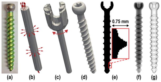
Example component models. (a) Photograph of a pedicle screw shaft. (b) Simple parameterization of the screw as a cylinder of bounded length and diameter. (c) Higher-order parameterization of the screw to include a polyaxial cap in addition to the cylindrical shaft. (d) Rendering of a device-specific (i.e., “exactly-known”) CAD model. (e) Illustration of a voxelized screw model. (f) DRR of the screw model. (g) Gradient magnitude of the screw model.
Both sKC and eKC models are represented as voxelized images, sampled onto a fine image grid with a nominal voxel size of 0.05 mm3 (Figure 1e), whereas pKC models are represented by triangular surface meshes to allow for flexible manipulation of their shape and size. Different realizations of pKC were evaluated, specifically 1) “pKC”, containing only a cylindrical shaft 2) “pKC +cap”, including a polyaxial cap, 3) “pKC +tip”, including a half ellipsoid tip, and 4) “pKC +cap +tip”, combining the last two.
2.2 3D-2D Registration
Previous work established a method for fast, robust registration of preoperative 3D images to intraoperative radiography/fluoroscopy,3,4 demonstrating 3D registration accuracy of target registration error (TRE) <2 mm using only two fluoroscopic views acquired at <20° separation (where 90° separation implies biplane acquisition).5 The current work extends the registration method to iteratively solve for the rigid transformation (
 ) such that a digitally reconstructed radiograph (DRR) from a known component (C) yields maximum similarity to intraoperative 2D projections (f, fixed images, acquired with a C-arm).
The similarity metric for image registration is normalized gradient correlation (GC), which computes the similarity between fixed radiographic (f) and moving DRR (m) images:6
| (1) |
| (2) |
thus computing the average normalized cross correlation (NCC) of the directional gradients. The similarity metric is used to define the objective function, which is solved using the covariance matrix adaptation evolution strategy (CMA-ES):7
| (3) |
where
 is the calibrated C-arm geometry at view θ, used to generate the DRR from component C for the tested transform
 using the forward projector operator (∘). Note that the transform, as well as component shape (in pKC) can be a function of optimized parameters.
Component DRRs for eKC and sKC models were computed using a standard ray-driven forward projector based on trilinear interpolation,8 with a nominal step-size equal to half the voxel-size (25 μm). Closed surface representation of pKC models on the other hand required the design of a new ray-driven forward projector, using Möller Trumbore ray-triangle intersection algorithm at its core to test for x-ray interaction.9 An inherent difficulty of this problem is the lack of a coherent ordering of the triangles, which may require each ray to traverse and sort all intersections before computing the line integral. One solution is to keep track of all intersections along each ray to sort them, which becomes infeasible due to memory limits in modern graphical processing units (GPU). Alternatively, sorting intersections on-the-fly by iteratively identifying the next-closest line segment would incur a computational cost of
 (N2). Instead, we devised an approach described below that is guaranteed to be
 (N), does not require additional memory for book-keeping, and does not assume convexity. The computation of the DRR in our approach is performed as:
| (4) |
where the line integral of a component mesh C at detector pixel u, v is given by the integration of all line segments between the source and an intersection point. The indicator function (1C) filters for triangles that contain an intersection, while the sgn function differentiates between incident rays (opposing surface normal n⃗) and exiting rays, subtracting and adding the distances respectively. Compared against the projector used in eKC and sKC, projecting a 1283-voxel image requires the same runtime as a 400-triangle pKC model (~7 ms on an NVIDIA GeForce GTX TITAN).
2.3 Experiments
The experiments were performed on an anthropomorphic spine phantom. The T11, L3, L4, and L5 vertebrae were targeted for the pedicle screw placement task (Figure 2a). Projection images were acquired from a mobile C-arm incorporating a flat-panel detector and a motorized orbit.10 Each acquisition spanned a 178° orbit, producing 200 projections, but only three projections at a time were used in the 3D-2D registration; the complete 200-projection scan also allowed CBCT reconstruction for truth definition and validation of tool placement.
Figure 2.
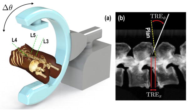
Experimental setup showing the (a) C-arm and rendering of the phantom with target trajectories, (b) figure depicting measured registration error at the tip and at the component principal axis.
The first set of experiments were designed to emulate guidance of a probe tool used to create pilot holes prior to screw placement. Projections were acquired as the probe was incrementally advanced free-hand along the planned screw trajectories. The sKC model of the probe was employed to compute its 3D pose from pairs of projections (θ1, θ2) separated by Δθ. The second set of experiments emulated the case in which the surgeon validates the correct placement of the implanted screw for QA purposes. Projections were acquired after each screw was placed.
Earlier work showed that two radiographic views acquired at <20° separation (where 90° separation implies biplane acquisition), was adequate for accurately solving the image-driven registration with TRE <1.5 mm. These results follow from exploiting magnification differences in extended patient anatomy and do not necessarily hold for components due to their small size. Moreover, certain views of the components are degenerate – e.g., the end-on view of a pedicle screw. One approach would be to optimize the angle of two required views based on the planned trajectory, assuming adherence to plan and requiring unique projections per screw. Instead, we simply used three views – AP, oblique, and lateral – such that for any screw, guaranteeing that at least two views are consistent with a non-degenerate pose determination.
3D registration accuracy was measured in terms of a positional error of the component tip (denoted TREx, Figure 2b), and as error in approach quantifying the deviation of its principal axis from the truth (denoted TREϕ). Given an estimated transformation composed of a rotation (R̂) and translation (t̂), the metrics can be defined as follows:
| (5) |
| (6) |
where the true transformations were obtained from a 3D-2D registration using the exact component model and all available projection views, excluding the ones used in registration to prevent potential bias.
3. RESULTS AND BREAKTHROUGH WORK
3.1 Image Guidance
Experiments evaluating image guidance performance validated the tracking of the probe and demonstrated successful registration resulting in overall translational error of <2 mm, and <0.5° deviation from the planned trajectory (Figure 3a b), when AP and LAT views were used. Further analysis of the angular separation of views revealed a similar trend observed in earlier work, 5 in which error minimized as Δθ approaches 90° (Figure 3b). Finally, the sensitivity to mismatch of the component model to the true device shape was analyzed as a function of deviation from the measured needle diameter (3.5 mm). The results show that the positional and angular errors were minimized when the diameter is close to the measured value (Figure 3d) with a tolerance of approximately ±0.5 mm still providing <2 mm accuracy.
Figure 3.
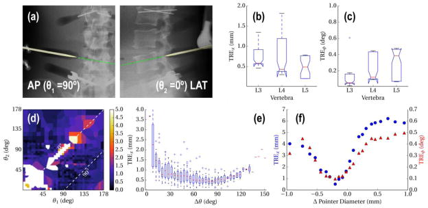
(a,b) Registration accuracy for repeated (×20) registration of the pointer poses acquired at each vertebra. (c) Sample overlay of the registered pointer model as it approaches L4. (d) Translational error as a function of individual views θ1, θ2, (e) and as a function of δθ. (f) Tolerance to model mismatch, measured as a function of deviation from the true tool diameter.
3.2 Quality Assurance
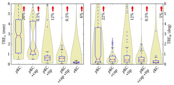
Among the tested pKC models (Figure 4), the simple cylindrical shaft model was able to achieve median TREx of 2.9±2.0 mm, and TREϕ of 0.5±1.9°. The large number of outliers observed in TREϕ were addressed by modeling the cap, thus preventing matching of the shaft onto the gradients from the cap region, and resulting in TREϕ of 0.5±0.4°. Similarly, the lack of modeling of the tapered tip caused outliers in TREx, as well as ~0.5 mm systematic offset error. Added modeling of the tip was shown to reduce these errors, resulting in TREx of 0.6±0.3 mm. Modeling both the cap and the tip was shown to mutually reduce errors in TREx and TREϕ as expected. Finally, in the case where exact specifications of the screw was available, eKC model was able to achieve median TREx of 0.2±0.1 mm, and TREϕ of 0.2±0.2°.
Figure 4.
Error in translational and orientation with respect to component models of increasing fidelity. Box plots highlight the median and interquartile range, while the violin plots in the back highlight the underlying distribution, such as the existence of a local minima in pKC +cap, due to lack of tip. Red arrows mark the percentage of outliers that exceed plot extent.
4. CONCLUSIONS
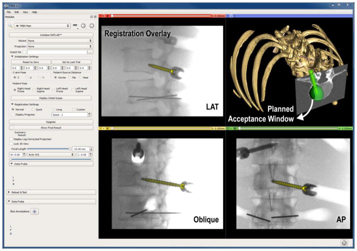
A novel method of utilizing standard intraoperative radiography for 3D guidance was presented, providing image guidance without the complexities of conventional tracking systems and providing additional functionality for surgical QA. Future work is planned for optimizing view angles with respect to the planned trajectory and component shape. Extension to deformable registration models is also planned, particularly for tools with long profiles and composite tools with multiple components.11 Integration with an in-house surgical navigation platform12 (TREK) is also underway (Figure 5) to provide enhanced visualization of 3D localization.
Figure 5.
Example interface of a 3D-2D guidance system, with registered pedicle screw overlaid on 2D projections (LAT, oblique and AP), and in 3D view contained within the green surgical plan (acceptance window).
Acknowledgments
This research was supported by NIH grants R01-EB-017226 and R21-EB-014964 and academic-industry partnership with Siemens Healthcare (XP Division Erlangen Germany).
References
- 1.Rampersaud YR, Simon DA, Foley KT. Accuracy requirements for image-guided spinal pedicle screw placement. Spine. 2001;26(4):352–9. doi: 10.1097/00007632-200102150-00010. [DOI] [PubMed] [Google Scholar]
- 2.Stayman JW, Otake Y, Prince JL, Khanna AJ, Siewerdsen JH. Model-based tomographic reconstruction of objects containing known components. IEEE transactions on medical imaging. 2012;31(10):1837–48. doi: 10.1109/TMI.2012.2199763. [DOI] [PMC free article] [PubMed] [Google Scholar]
- 3.Otake Y, Schafer S, Stayman JW, Zbijewski W, Kleinszig G, Graumann R, Khanna AJ, Siewerdsen JH. Automatic localization of vertebral levels in x-ray fluoroscopy using 3D-2D registration: a tool to reduce wrong-site surgery. Physics in medicine and biology. 2012;57(17):5485–508. doi: 10.1088/0031-9155/57/17/5485. [DOI] [PMC free article] [PubMed] [Google Scholar]
- 4.Uneri A, Wang AS, Otake Y, Kleinszig G, Vogt S, Khanna AJ, Gallia GL, Gokaslan ZL, Siewerdsen JH. Evaluation of low-dose limits in 3D-2D rigid registration for surgical guidance. Physics in medicine and biology. 2014;59(18):5329–5345. doi: 10.1088/0031-9155/59/18/5329. [DOI] [PubMed] [Google Scholar]
- 5.Uneri A, Otake Y, Wang AS, Kleinszig G, Vogt S, Khanna AJ, Siewerdsen JH. 3D-2D registration for surgical guidance: effect of projection view angles on registration accuracy. Physics in medicine and biology. 2014;59(2):271–87. doi: 10.1088/0031-9155/59/2/271. [DOI] [PMC free article] [PubMed] [Google Scholar]
- 6.Gottesfeld Brown LM, Boult TE. Registration of planar film radiographs with computed tomography. Proc. Work. Math. Methods Biomed. Image Anal; 1996.pp. 42–51. [Google Scholar]
- 7.Hansen N, Ostermeier A. Completely derandomized self-adaptation in evolution strategies. Evolutionary computation. 2001;9(2):159–95. doi: 10.1162/106365601750190398. [DOI] [PubMed] [Google Scholar]
- 8.Peters TM. Algorithms for Fast Back- and Re-Projection in Computed Tomography. IEEE Transactions on Nuclear Science. 1981;28(4):3641–3647. [Google Scholar]
- 9.Moller T, Trumbore B. Fast, Minimum Storage Ray-Triangle Intersection. Journal of Graphics Tools. 1997;2(1):21–28. [Google Scholar]
- 10.Siewerdsen JH, Moseley DJ, Burch S, Bisland SK, Bogaards A, Wilson BC, Jaffray DA. Volume CT with a flat-panel detector on a mobile, isocentric C-arm: pre-clinical investigation in guidance of minimally invasive surgery. Med Phys. 2005;32(1):241–54. doi: 10.1118/1.1836331. [DOI] [PubMed] [Google Scholar]
- 11.Stayman JW, Otake Y, Uneri A, Prince JL, Siewerdsen JH. Model-based known component reconstruction for computed tomography. Am Assoc Phys Med. 2011;38(6):3796. [Google Scholar]
- 12.Uneri A, Schafer S, Mirota DJ, Nithiananthan S, Otake Y, Taylor RH, Gallia GL, Khanna AJ, Lee S, et al. TREK: an integrated system architecture for intraoperative cone-beam CT-guided surgery. International journal of computer assisted radiology and surgery. 2012;7(1):159–73. doi: 10.1007/s11548-011-0636-7. [DOI] [PMC free article] [PubMed] [Google Scholar]


