

Abstract
In the past decade, several functional extensions of optical coherence tomography (OCT) have emerged, and this review highlights key advances in instrumentation, theoretical analysis, signal processing and clinical application of these extensions. We review five principal extensions: Doppler OCT (DOCT), polarization-sensitive OCT (PS-OCT), optical coherence elastography (OCE), spectroscopic OCT (SOCT), and molecular imaging OCT. The former three have been further developed with studies in both ex vivo and in vivo human tissues. This review emphasizes the newer techniques of SOCT and molecular imaging OCT, which show excellent potential for clinical application but have yet to be well reviewed in the literature. SOCT elucidates tissue characteristics, such as oxygenation and carcinogenesis, by detecting wavelength-dependent absorption and scattering of light in tissues. While SOCT measures endogenous biochemical distributions, molecular imaging OCT detects exogenous molecular contrast agents. These newer advances in functional OCT broaden the potential clinical application of OCT by providing novel ways to understand tissue activity that cannot be accomplished by other current imaging methodologies.
Introduction
Based on the principle of low coherence interferometry, OCT is a relatively recent imaging modality that was proposed in the early 1990s.1 It measures depth-resolved reflections of near-infrared light to create cross-sectional images of tissue with micrometer resolution.2
The capability of OCT to noninvasively image tissue at the micrometer scale introduces the idea of an “optical biopsy”, in which information about tissue can be gained from imaging, instead of a traditional biopsy requiring histopathology.3 OCT has already found clinical relevance in ophthalmology for diagnosis of retinal diseases where it is a natural fit since the eye is low light scattering.4 OCT has also been explored for other applications—mainly cardiovascular, oncologic, and dermatologic—but these have yet to reach broad clinical use.5–7
To date, OCT has spurred a significant body of entrepreneurial and scientific work: more than 50 OCT companies, more than 100 research groups involved in OCT, more than 1,000 OCT patents issued, and more than 10,000 research articles published.8 As OCT evolves, the clinical application of OCT can be extended by providing functional information about live, intact tissue beyond just structural characteristics. Various functional extensions of OCT have been developed to realize this potential, including Doppler OCT, polarization sensitive OCT, optical coherence elastography, spectroscopic OCT, and molecular imaging OCT. Currently, DOCT, PS-OCT and OCE are the most advanced of these approaches, having been applied to human tissues either in vivo or ex vivo.
SOCT and molecular imaging OCT are newer functional techniques that have been tested primarily in animal models. SOCT uses endogenous differences in absorption and scattering, while molecular imaging OCT employs exogenous contrast agents to target specific molecules. Both OCT extensions have been studied in animal models for imaging cancerous lesions and tissue vasculature. As these two techniques have not been well reviewed in the literature, SOCT and molecular imaging OCT are discussed more extensively in this review. Overall, this review discusses key advances in instrumentation, theoretical analysis, signal processing and clinical application of functional OCT.
Doppler OCT (DOCT)
Doppler optical coherence tomography (DOCT) is arguably the most widely used form of functional OCT where additional information is obtained beyond the inherent contrast due to variations in index of refraction. Similar to the acoustic Doppler effect, the speed of a moving particle in the sample can be determined by measuring the frequency shift imparted on light scattered by the particle. The classic example of Doppler shifts is the increase in frequency of an approaching train whistle followed by the decrease in frequency as it passes and departs. This section focuses primarily on recent clinical applications as well as performance specifications and limitations that are most relevant to clinical use. A brief overview of the development, commercialization, and variations of DOCT is also provided. More detailed descriptions of instrumentation, data processing methods, and non-clinical studies can be found in previously published review articles and book chapters.9–11
Development
Development of Doppler OCT in the laboratory has been aided by a relatively low need for additional instrumentation and few regulatory barriers, since only adaptions to signal processing methods are required to implement the approach. While some work has been done in humans and tissue phantoms, this approach has been primarily used in small animal imaging of zebrafish, tadpoles, mice, rats, birds, and other animals. For example, Yang et al. used DOCT to image the cardiac dynamics of Xenopus laevis tadpole (Figure 1).12,13 Larina et al. used swept source (SS)-DOCT to image and analyze heartbeat and blood flow in live rat embryos with resolution at the single cell level.14 Peterson et al. used four-dimensional OCT with Doppler, i.e. three-dimensional (3D) OCT images taken over time, to measure the shear stress in the developing hearts of quail embryos.15
Figure 1.

[a] Block diagram of the DOCT system. A broadband light source with a polarized output power of 5 mW at center wavelength λ0=1.3 μm and bandwidth Δλ = 63 nm is coupled into a single-mode fiber optic interferometer. An optical circulator is used to increase the signal-to-noise ratio. The reference arm uses a Michelson interferometry configuration with a rapid scanning optical delay (RSOD) operating a 8 kHz. The sample arm uses a hand-held scanner, which consists of a fiber probe tip at the end of a SMA-28 fiber, attached to a rotor disk. LS, light source; PC, polarization controller; OC, optical circulator; 3db, 50-50 fiber coupler; PMD, phase modulator driver; I&Q, in-phase and quadrature demodulator; SD-1&2, scanner drivers; COMP, computer. [b] Hardware and software signal conditioning. TIA, trans-impedance amplifier; HPF & LPF, high- and low-pass filters; DGC, depth-gain-compensation amplifier; DF, depth feedback signal; SIN & COS, 0° and 90° shifted carrier frequency, synchronized to the PMD; ADC, analog-to-digital converter; BGC, digital bias and gain compensation. [c1–c4] DOCT video of Xenopus tadpole’s left (L) and right (R) aortic branches, at 8 fps. [c1] is a structural (B-mode) video of the aortic branches in cross-section, with a smaller vessel labeled “V” in the video. Scale bar = 500 μm. [c2] is a 2x zoom image of the area in the yellow rectangle in [c1]; the break in the yellow line indicates where Doppler spectrum information was collected and encoded into audio format, demonstrating the velocity distribution within “L.” Scale bar = 250 μm. [c3] is a color Doppler video that shows the corresponding velocity map in the cross-section. There is pulsatile blood flow in L and R. The Doppler angle (α) is estimated to be approximately 63° for R. The small blood vessel (V) was better visualized here and diameter was estimated to be less than 70 μm. [c4] is a velocity variance video and shows increased variance of flow within the left and right aortic branches. [Reprinted with permission from Yang et al., originally published in Optics Express 11, 1650–1658 (2003).]
The generation of DOCT images requires additional signal processing, but as noted, the system hardware may require little or no modification. The processing of Doppler signals is different for time domain OCT versus Fourier domain OCT and significant additional computer resources may be needed, particularly if the flow information is desired in real time.
In time domain OCT, the interference signal is already centered on a fixed Doppler frequency due to the moving mirror in the reference arm. Coherent demodulation with a lock-in amplifier set to this fixed frequency is used to detect the interference fringes generated by light scattered from the sample. The magnitude of this signal is proportional to the number of photons scattered from a given depth and provides the signal in the OCT image. Any motion in the sample can add or subtract from the signal content at this fixed frequency. To obtain the Doppler shifted signal, overlapped short-time Fourier transforms at a given reference arm position are used. The average velocity in the sample at a given depth is then given by where fs is the frequency shift from the reference arm Doppler frequency, λo is the center wavelength of the source, n is the local index of refraction of the sample and θ is the angle of the OCT beam relative to the motion of the particle within the sample. The range of speeds that can be measured is dictated by the bandwidth of the lock-in amplifier used for demodulation while the resolution is determined by the number of points in the short-time Fourier transform.
In Fourier domain OCT (FD-OCT), data are acquired from the whole sample depth simultaneously with a fixed pathlength in the reference arm so the approach for making Doppler measurements differs. Here two or more axial scans (A-scans) are acquired at a given lateral location and the phase difference between successive measurements is calculated. This phase variation is proportional to the speed of the target within the sample, ν, with a relationship given by where Δϕ is the phase shift between A-scans, T is the time between A-scans, λo is the center wavelength of the source, n is the index of refraction of the sample, and θ is the angle of the OCT beam relative to the motion of the particle within the sample. The signal phase is calculated from the Fourier transform of the frequency resolved intensity data. Since the intensity measurements are real valued, a Hilbert Transform is used to obtain the phase value. The Hilbert Transform consists of a Fourier Transform, where the negative frequency values are set to zero, followed by an inverse Fourier Transform. The final complex Fourier Transform will produce both the scattered intensity as a function of depth in the sample and the phase at each depth point. By comparing subsequent A-scans at the same point, the rate of change of the phase can be calculated.
Commercialization
Commercial systems with DOCT are available for research and clinical applications. Thorlabs (Newton, New Jersey) offers Doppler OCT as an option on both spectral domain (SD)-OCT systems operating at 930 nm and SS-OCT systems operating at 1300 nm. In September 2014, Optovue, Inc. (Fremont, California) introduced the Angiovue OCT angiography system for 3D visualization of the retinal vasculature. Of note, Angiovue is not yet approved for sale in the United States.
Limitations
As shown by Izatt et al., the range of speeds that can be measured in Fourier domain OCT systems is determined by the method by which A-scans are acquired.16 For both SD-OCT and SS-OCT the slowest speed that can be measured is set by the phase noise in the system, which is given by where SNR is the shot noise-limited SNR of the imaging system. The upper limit on detection speed is set by the integration time for a single pixel in the system, which varies for SD and SS system. For SD-OCT, this is given by where D is the detector duty cycle, and for SS-OCT, this is given by , where M is the number of acquisitions within a single frequency sweep of the laser. Thus, SS-OCT can measure a larger range of speeds in the sample for a given A-scan rate of the system.
Another limitation in Doppler OCT is that time varying signals generated by bulk motion, as are typically seen in biological samples, can confuse the true Doppler signal. The most common technique to minimize the impact is to calculate Doppler shifts for the entire A-scan and look for common mode features. The common features are then assumed to be a result of bulk sample motion and subtracted to yield the Doppler signals of interest.
In all modes of Doppler imaging, accurate measurement of velocity requires knowledge of the angle θ between the OCT beam and the direction of the velocity in the sample. For blood vessels and capillary phantoms, it may be possible to measure this angle by acquiring a 3D OCT image and then identifying the location of the vessel or capillary within the volume image either manually or with automatic segmentation approaches. Huang et al. showed that the location and angle of retinal vessels could be identified by using two concentric circular scans around the optic disk. In this approach, the relative position of a blood vessel in the two OCT cross sections is used to calculate the Doppler angle between the beam and blood vessel.17
Variations
Several variations on DOCT have been developed. Wang et al. developed a technique referred to as optical angiography (OAG), which uses an SD-OCT system with a modulation in the reference arm pathlength.18 In this implementation, the spectrometer operated at 10,000 lines per second, and the reference arm was modulated at the same frequency as the two dimensional (B-scan) rate (10 Hz) with a path length modulation magnitude of 50 microns. Motion in the sample, which produced a Doppler frequency greater than the Doppler frequency due to the reference arm modulation of 1.25 kHz, showed up in the complex conjugate part of the Fourier domain OCT image while the standard OCT image remained unchanged. Using this method, blood perfusion in a living adult mouse was imaged with higher signal to noise than phase resolved DOCT.
In another approach, Fingler et al. used phase variance as a contrast mechanism to distinguish moving versus fixed scatterers in both an Intralipid phantom and live zebrafish.19 This system used SD-OCT with a center wavelength of 840 nm and a 25 kHz A-scan rate. This study showed that phase variance has a lower noise threshold compared to Doppler OCT and therefore can image motion without the angle dependence of Doppler, enabling detection of motion that is nearly perpendicular to the angle of incidence. In a similar approach, Mariampillai et al. used a Fourier domain mode locked laser centered at 1310 nm and operating at 43 to 67 kHz, to demonstrate speckle variance OCT.20 This system provided high contrast between blood vessels and surrounding tissue, but did not provide any velocity information. However, there is significant utility in this approach as it could detect conditions such as vascular shutdown and transient vessel occlusion in near real time. Similar to the phase variance technique, the speckle variance was much more sensitive than Doppler detection for angles of incidence approaching 90 degrees.
Variance processing methods in FD-OCT have enabled depth-resolved visualization of capillary beds in the retina by acquiring A-scan data in the 100 kHz regime. However, acquisition time lasts several seconds, during which subject movement will alter visualization of the capillary beds. To address this limitation, Hendargo et al. developed a technique to eliminate motion artifact in speckle variance FD-OCT by creating a composite image of the retinal vasculature from multiple, sequentially-acquired volumes of data (Figure 2).21
Figure 2.

With elimination of motion artifact, speckle variance Fourier domain OCT is able to segment layers of the human retina by layer-specific angiography. [a] Individual, motion corrected images of the retina with color encoded vessel depth are shown. Red indicates superficial vessels while blue indicates deeper vessels. [b] A widefield mosaic of the retinal vasculature with color-encoded depth combines information from the individual images. Reprinted with permission from Hendargo et al., originally published in Biomedical Optics Express 4.6, 803–821 (2013).]
Clinical Application
DOCT has shown potential for multiple clinical uses in ex vivo or in vivo human studies by observing modulation in blood flow in the retina, GI tract, and kidneys. In ophthalmology, OCT is used to render in vivo cross sectional views of the retina to diagnose pathologies such as macular holes, macular pucker, and vitreo-macular traction. DOCT can also potentially be applied to monitor progression of ocular pathologies that cause changes in blood flow dynamics, such as diabetic retinopathy and glaucoma. Yazdanfar et al. first demonstrated in vivo color DOCT in the human retina using a time domain system.22 This system was used to image Doppler shifts up to 3.3 kHz in artery-vein pairs with an axial resolution of approximately 20 μm and an acquisition time of less than 60 seconds. White et al. demonstrated the first spectral domain OCT imaging of an in vivo human retina with an A-scan rate of 29 kHz.23 The instrument was capable of detecting Doppler shifts between 24 Hz and 14.66 kHz, providing a dynamic range of over 600. By acquiring a sequence of 95 B-scans, the integrated flow of an artery-vein pair was measured over 3.28 seconds revealing a pulse rate of 73 beats per minute.
In the GI tract, DOCT can be applied to observe modulated blood flow due to certain pathologic processes such as esophageal varices and neoplasms. Yang et al. developed an endoscopic DOCT system and imaged both normal and pathologic tissues of 22 patients in a feasibility study.24 Structural and microcirculatory patterns differed from site to site with observed differences between normal and diseased tissue. This endoscopic system uses a 2-millimeter probe that is compatible with the auxiliary channel of most endoscopes and achieved a velocity resolution of approximately 100 μm/s, which is 10 to 100 times better than can be measured with Doppler endoscopic ultrasound.
In solid organs, DOCT has been used to study microcirculation in kidneys. Blood flow was initially measured in vivo in rat kidneys, and the effects of mannitol and angiotensin II were observed.25 The instrument provided lower and upper velocity detection limits of 0.01 and 3.9 mm/s, respectively. The same group then used DOCT to diagnose acute tubular necrosis in human donor kidneys. Twenty-eight patients were enrolled in the study, and each transplanted kidney was imaged prior to transplant (ex vivo), and then again following transplant and reperfusion (in vivo). Tubule size/shape and density/uniformity were grouped into categories of poor, moderate and good. The kidney with poorest post-transplant function did not show open tubules, and the patient suffered delayed graft function (Figure 3).26 DOCT has also been explored in other anatomical sites with groups having measured blood flow in skin and lips in healthy human subjects.27–29
Figure 3.

[a] Transplant surgeons use the sterilized hand-held OCT probe to image a transplanted human donor kidney in the operating room. Both surgeons are looking at real-time images of the functioning kidney. [b, c] OCT image of a donor kidney shows open tubules (black arrows) prior to transplantation [b], and another donor kidney shows no open tubules prior to transplantation [c]. The donor seen in B had a rapid return to normal function (2 days), while that in C did not recover normal values until nearly two weeks. Brackets indicate the kidney capsule. White arrows indicate Tegaderm, a clear adhesive tape. [Reprinted with permission from Andrews et al., originally published in Journal of Nephrology and Therapeutics 4, 2161-0959 (2014).]
Although DOCT is not actively in clinical use, it offers significant potential benefits to physicians. It has been shown that DOCT can accurately measure blood flow in the retina, GI tract, and kidneys with micron-level spatial resolution and velocity resolution up to 10 μm/s. Computational methods to remove bulk-motion artifacts and precisely determine the angle between the illumination beam and direction of flow have also been developed. These studies and recent developments suggest that DOCT could be an important clinical tool to diagnose potentially pathologic tissues and monitor responses to treatment.
Polarization sensitive OCT (PS-OCT)
Another widely studied form of functional OCT is polarization sensitive OCT (PS-OCT), which collects light resolved by polarization and thus can reveal birefringence in a sample. The birefringence properties of a biological sample can provide a useful contrast mechanism in samples with a high degree of microscopic structural order such as cartilage, teeth, and blood vessel walls. Using multiple polarizations to image birefringence using interferometry was one of the earliest applications of OCT: in 1992, Hee et al. demonstrated a polarization-sensitive low-coherence reflectometer and characterized the birefringence of a wave plate and ex vivo calf coronary artery tissue.30
Development
For PS-OCT, the system complexity necessarily increases since the approach requires collection of OCT signals at more than one polarization. The data from each polarization channel are typically processed independently until the final stage where the two images are analyzed to provide polarization contrast. There are numerous methods for collecting multiple polarizations. In an early example, de Boer et al. used a time domain OCT system with a rotating quarter waveplate in the reference arm to collect OCT signals with varying polarizations as a function of time.31 Synchronizing the detection with the rotating waveplate enabled extraction of the OCT signal of the vertical and horizontal polarizations. This system was initially demonstrated through application to imaging fresh bovine tendon.
The next version of de Boer’s system used a linear polarized light source set at 45° and a polarizing beam splitter (PBS) in the collection arm to simultaneously capture two orthogonal polarizations.32 Each polarization was collected by a separate detection channel with independently associated electronics. This was still a free space system, but enabled measurement of the depth-resolved Stokes parameters in rodent muscle and skin. Saxer et al. then developed this approach further by building a high-speed fiber-based time domain OCT system with a polarization modulator in the source arm.33 This system operated at 1310 nm and was used to measure birefringence of in vivo human skin. Again the detection arm used a PBS with two detectors and independent electronics for each channel.
The next advance in time domain PS-OCT was 3D PS-OCT, first demonstrated by Pircher et al. in 2004.34,35 The center wavelength was again at 1310 nm, but used a different interferometer topology. The Mach Zehnder configuration contained two PBS detection setups, with a total of four detectors, thus providing balanced detection for each orthogonal polarization; this is now the standard architecture in time domain PS-OCT. Human skin was measured in vivo with an acquisition time of 150 seconds per site.
The transition to Fourier domain OCT offers increased imaging speeds due to improved SNR36, but for PS-OCT, the approach requires more complex collection schemes in place of the standard spectrometer. Gotzinger et al. developed a high speed PS-OCT system using two independent spectrometers each operating at 20,000 lines per second (Figure 4).37 This implementation used a free space interferometer with a PBS in the collection arm and fiber optic coupling after the PBS to deliver light to the spectrometers. Yamanari et al. moved to a fiber-based interferometer and located the PBS inside the spectrometer.38 The PBS was placed after the grating and focusing lens and two CCD cameras were then used to capture the orthogonal polarizations at 27,000 lines per second. This system operated at 840 nm and was used to image chicken breast muscle, a finger pad and a caries lesion in a tooth.
Figure 4.

[a] Schematic drawing of spectral domain PS-OCT instrument. After vertical polarization, light emitted from a super luminescent diode (SLD) illuminates a Michelson interferometer, where it is divided into sample and reference beams by a non-polarizing beam splitter (NPBS). The reference light transmits a variable density filter, a glass plate, a quarter wave plate (QWP) at 22.5°, and is reflected by a mirror. The sample beam passes a QWP oriented at 45° to provide circularly polarized light to the sample. FC: fiber coupler; POL, polarizer; VDF, variable density filter; M, mirror, SC, galvo scanner; L, lens; S, sample; PMF, polarization maintaining fiber; HWP, half wave plate; DG, diffraction grating; LSC, line scan camera. [b1–b3] B-scan images of human fovea in vivo: [b1] intensity (log scale), [b2] retardation, [b3] fast axis orientation. [b2] shows low retardation in most retinal layers, as evidenced by the dark blue color. However, the last strongly reflecting layer in [b1] shows retardation values changing randomly in transverse direction, yielding an average green color in [b2]. This layer is probably the retinal pigment epithelium (RPE); localization of this layer is important for diagnosis of pathologies such as age related macular degeneration (AMD). In [b3], the polarization scrambling effect of the last layer, likely the RPE, is again observed. The color change to light blue is probably caused by the birefringent Henle’s fiber layer—the layer of inner cone fibers in the central area of the retina—that is located within the weakly backscattering area marked “H.” Image size is 3 mm horizontal and 0.75 mm vertical. Values on color bars are in degrees, with areas below a threshold intensity displayed in grey. [Reprinted with permission from Gotzinger et al., originally published in Optics Express 13, 10217–10229 (2005).]
In SS-OCT, the collection optics typically consists of either a single detector or two detectors in a balanced configuration so the PS implementation of SS-OCT is similar to that used in time domain. Interferometers for SS-OCT are typically fiber optic based so a fiber coupled polarizing beamsplitter may be used along with two fiber-coupled photodiodes. Polarization maintaining fibers must be used in these schemes to preserve the polarization dependence of the signal. Balanced detection may be implemented by extending this scheme to include a circulator and two fiber coupled polarizing beamsplitters. This scheme requires four detectors and the level of suppression of the opposite polarization will be limited by the extinction ratios of the two polarizing beamsplitters.
Numerous groups have developed polarization sensitive OCT systems based on swept source lasers. Some examples include Yamanari et al., who developed a fiber-based polarization-sensitive SS-OCT system using continuous source polarization modulation.39 This system used a swept source from Santec Laser (Japan), centered at 1310 nm and operating at a sweep rate of 20 kHz. This system was demonstrated by imaging chicken breast muscle ex vivo and corneal angle from in vivo human anterior eye segment.
Oh et al. developed a parallel acquisition system by generating two polarizations in the source arm and then modulating them at two different frequencies so that a single detector set can simultaneously capture information from both polarizations using frequency resolved detection.40 Using a swept source laser with a center wavelength of 1305 nm and an A-scan rate of 50 kHz, this system was used to generate intensity and phase retardation images of chick muscle ex vivo, human finger in vivo, and human coronary artery ex vivo.
Baumann et al. developed a high-speed polarization sensitive system with a passive polarization delay unit.41 This delay unit was placed in the sample arm and generated a 1.8-millimeter pathlength difference between the two polarizations. The detector scheme for this system was a standard four-detector setup with balanced detection for each polarization. A 1040 nm swept laser from Axsun Technologies (Billerica, MA) with a 100 kHz repetition rate was used with a semiconductor optical amplifier (SOA) from Inphenix Inc. (Livermore, California). The offset in polarizations resulted in two images in a B-scan with a depth offset between them of 1.8 millimeters. 3D retinal imaging was performed on volunteers with volumes of 500 × 100 A-scans acquired in ~0.55 seconds.
Commercialization
The above section reviews only a few of the many PS-OCT systems developed in academic labs around the world. However, similar to Doppler OCT, there has been significant research into PS-OCT systems, but few commercial offerings. To date, the only commercially available PS-OCT is a module from Thorlabs that can be added to their SS-OCT systems. This requires a hardware change, but is available as an upgrade to any already deployed swept source systems.
Clinical Application
Structural changes associated with certain disease processes cause changes in birefringence that can be measured with PS-OCT. PS-OCT has been applied to study birefringence in the eye, skin, esophagus, breast tissue, cartilage, and teeth. For example, PS-OCT was used to image hard exudates in eyes of 16 patients with diabetic macular edema with an axial resolution of less than 5 μm.42 Hard exudates in the eye indicate an impairment of the blood-retinal barrier, leading to retinal swelling and edema. PS-OCT enabled 3D imaging of hard exudates throughout retinal layers by measuring the uniformity of polarization across each image with a sliding evaluation window. Automated detection of hard exudates with PS-OCT showed reasonable correspondence with manual grading of color fundus photographs, which is the current gold standard for diagnosis.
PS-OCT has also been used to measure the birefringence of collagen, which transitions from a rod-like alpha helix to a random coil conformation after heating. In normal human skin, which contains well-ordered collagen, the birefringent nature of the tissue can be observed with PS-OCT. In contrast, the ordered collagen structure is disrupted in burned tissue resulting in decreased birefringence (Figure 5). The mean difference in phase retardation between orthogonal polarization states was 0.401 and 0.249 °/μm for normal and burned skin, respectively. This difference was statistically significant and over an order of magnitude larger than the measurement accuracy (0.003 °/μm).43
Figure 5.

[a1–a3] Histology [a1], OCT [a2], and PS-OCT [a3] images of normal human skin on the torso. In [a2], the epidermal (e) and dermal (d) layers are indicated with structures such as blood vessels and appendages in evidence. In [a3], the strong transition from black (0° phase retardation) to white (180° phase retardation) and back to black (360° phase retardation) within the depth of the dermis indicates birefringence, which is attributed to the presence of collagen fibers. [b1–b3] Histology [b1], OCT [b2], and PS-OCT [b3] images of partial thickness burned human skin. The histology image [b1] shows loss of the epidermal layer, absence of pilosebaceous appendages, and fusion of collagen bundles. The partial thickness burn demonstrates greater homogeneity in the conventional OCT image [b2] and a weaker transition from black to white in the PS-OCT image [b3]. [Reprinted with permission from Pierce et al., originally published in Burns 30, 511–517 (2004).]
Other prospective applications of PS-OCT deserve mention. For example, PS-OCT has shown potential in assessing changes in cartilage organization. In one study, PS-OCT images were graded on a ternary scale by a blinded investigator and compared to histology from the same location. There were no significant differences in the paired scores derived from PS-OCT and histology.44 Another application has been found in the area of dentistry. Because dental enamel contains birefringent hydroxyapatite crystals, PS-OCT can be used to image changes in birefringence caused by dental caries with an initial in vitro demonstration having been completed.45 In summary, PS-OCT can measure birefringence in vivo in a variety of biological tissues. Recent demonstrations have achieved high spatial resolution and accuracy in determining the phase difference between orthogonal polarization states. This additional structural information can be leveraged to diagnose disease, evaluate injury, or monitor therapeutic response.
Optical coherence elastography (OCE)
Unlike Doppler OCT and PS OCT, which use endogenous contrast mechanisms within a sample, optical coherence elastography (OCE) adds an externally induced mechanical stimulus alongside OCT to obtain structural information about the elasticity of a sample. Manual palpation has been used for centuries to detect tumors, but is very subjective. Elastography uses a known mechanical modulation along with imaging to provide a quantitative measure of the strains and elastic moduli of tissue.46 The approach was first developed using ultrasound (sono-elastography) imaging47 and then later with MRI.48
Development
Recently, the technique of sono-elastography has been combined with OCT to take advantage of the high resolution of OCT imaging. Optical coherence elastography (OCE) was first implemented by J. Schmitt in 1998 using a time domain OCT system and a piezoelectric actuator to generate linear displacements of 0 to 100 microns at rates up to a few Hz.49 This system was used to image mechanical properties of gelatin phantoms, ex vivo pork meat, and in vivo human skin.
Later efforts by Adie et al. resulted in an OCE system with a tunable piezoelectric stack and measured the tissue response as a function of the drive frequency over the range of 25 Hz to 1 kHz (Figure 6).50 This system can measure the natural vibration modes or resonances up to the maximum drive rate. This approach was used to measure the complex mechanical spectra of rat mammary tumor margins, showing a difference in resonance frequencies between the normal tissue and the tumor.
Figure 6.

[a] Schematic diagram of the OCE system. A Nd:YVO4-pumped titanium:sapphire laser acts as a broadband source, providing a center wavelength of 800 nm and a bandwidth of 100 nm. The sample arm uses a PZT stack to excite the sample sinusoidally in the axial direction. The sample is bounded by a coverslip from below and a round wedge prism from above. The wedge is able to move against its spring; during alignment, it is lowered to make contact with the sample and then moved another 10 μm to apply a constant preload. [b] Flowchart of the processing steps used to compute the spatially-localized complex mechanical response of the sample. [c] Complex mechanical response images for rat muscle tissue. OCT image (left) is accompanied by images of displacement amplitude (top row) and phase (bottom row), at two different frequencies (83, 125 Hz). Image dimensions are 750 μm (optical depth) by 2 mm (lateral). Arrows in the displacement image at 83 Hz indicate regions with different OCE and OCT contrast. [Reprinted with permission from Adie et al., originally published in Optics Express 18, 25519–25534 (2010).]
In 2010, Liang et al. built a dynamic OCE system that acquired B-scans during an applied mechanical compression.51 This approach used the phase difference between adjacent A-scans to measure scatterer velocity in the axial direction. Similar to Adie50, multiple driving frequencies were used, including 20, 45, 100, and 313 Hz. For the lowest three drive frequencies, an A-scan rate of 1 kHz was used, but for the 313 Hz drive frequency, the imaging A-scan rate was increased to 10 kHz. The system was tested on a three-layer tissue phantom and then on ex vivo rat tumor. The different excitation frequencies permitted differentiation of adipose and tumor tissue.
B. Kennedy et al. presented the first 3D OCE images in 2011.52 This approach used an SD-OCT system with an A-scan rate of 5 kHz and mechanical excitation at 125 Hz to generate 3D-OCE imaging of normal and hydrated skin in vivo. The light source was a pumped titanium-sapphire laser with a center wavelength of 800 nm and a bandwidth of 100 nm providing an axial resolution of 2.8 μm. Images were acquired from the skin on the tip of the middle finger with a preload generated by pressing the finger against the actuator window and strapping it in place. The skin was then hydrated in warm water for 30 minutes and reimaged. The study observed a more elastic response of the stratum corneum for the case of hydrated skin.
To overcome the depth limitation of OCT to just the superficial layers of tissue, K. Kennedy et al. integrated an OCT system with a needle biopsy probe to image deeper within human breast tissue (Figure 7).53 The OCT system ran at a 5 kHz A-scan rate with a center wavelength of 836 nm. A motorized stage was used to drive the needle into the tissue at a known speed, with the needle tip providing the mechanical compression for OCE imaging. The needle probe did not offer any lateral scanning, so only provided mechanical information obtained from analyzing the forward looking A-scan.
Figure 7.

[a] Schematic of setup for in situ ultrasound-guided measurements in a human mastectomy sample. [b] Sonogram captured during ultrasound-guided needle OCE in a human mastectomy sample. [c] M-mode OCT image during needle insertion toward tumor. [d] Histology acquired along path of needle insertion. Cyan and green brackets mark the estimated regions of tissue scanned at t = 1 s and t =18 s, respectively. [e, f] Average OCT A-scans [e1, f1] and corresponding displacement [e2, f2] for time points indicated by the dashed cyan and green lines in [c]. The red stars indicate locations of the tissue interfaces estimated from the displacement data, and the slopes of the least-squares fitted black lines indicate local strain. In the displacement traces [e2, f2], the adipose tissue shows greater strain than tumor. The interface between adipose and tumor is detected by a sharp change in strain. [Reprinted with permission from Kennedy et al., originally published in Journal of Biomedical Optics 18(12), 121510 (2013).]
A more comprehensive review of OCE with a particular emphasis on the signal processing employed for various implementations of OCE can be found in Sun et al.54 This review also provides details on the use of intravascular OCE for atherosclerotic plaque detection, which is further described below.
Clinical applications
Clinical use of OCE relies on the principle that elastic properties of tissues can change due to disease. Edema, fibrosis, and calcification are all known to change the elastic modulus of the extracellular matrix. Tumors are often stiffer than normal surrounding tissue. Current applications of elastography include assessment of atherosclerotic plaques within arteries, examination of breast or brain tissue for malignancy, and evaluation of lung tissue for disease.
Intravascular ultrasound elastography has made significant strides and is able to extract arterial radial strains with a spatial resolution of 200 μm. However, vulnerable atherosclerotic plaques have structural elements on the order of 50–200 μm, below the resolvable limit of intravascular ultrasound. Intravascular OCE has inherently higher resolution and potential to provide high resolution characterization of strain in tissues that lie 1.0–1.5 mm below the vessel surface, which is the region most susceptible to plaque disruption.55 Intravascular OCT is able to resolve thin cap fibroatheromas (TCFA), which are intracoronary plaques with a large lipid-rich necrotic core covered by a thin, inflamed fibrous cap, that are believe to be responsible for acute coronary syndrome.55–61 By detecting changes in the mechanical properties due to TCFA formation, intravascular OCE may be able to predict plaques at risk for rupture.
Similar to application to intravascular plaques, OCE can identify intravascular blood clots. Oldenburg et al. used rehydrated, lyophilized platelets loaded with superparamagnetic iron oxides that adhere to sites of vascular endothelial damage, in order to identify the presence of clots. Using an approach termed magneto-motive OCT, where a magnetic field is used to mechanically displace magnetic nanoparticles, elastometry of simulated clots was conducted. The measured data were analyzed to determine the fundamental resonance frequency of the clot, which showed a qualitative positive correlation to its fibrinogen content.62
OCE has been evaluated for other clinical applications, such as eye, skin, breast cancer and cystic fibrosis.63–66 Ford et al. demonstrated that corneal edema and collagen cross-linking affected the mechanical properties of human ex vivo corneas with OCE. Local lateral versus axial displacement ratios were 0.035, 0.021, and 0.014 μm/μm for edematous, normal, and collagen cross-linked human corneas, respectively. The differences were statistically significant and demonstrated that OCE can quantify clinically-relevant mechanical properties in the cornea.64 Liang and Boppart used OCE to measure Young’s moduli of in vivo human skin at different locations on the arm. They demonstrated that Young’s moduli are dependent on the site, stimulation direction and frequency. For example, with a driving frequency of 50 Hz, they measured Young’s moduli of 101.180, 68.678, and 24.910 kPa from the volar forearm, dorsal forearm, and palm, respectively. Different conditions, such as hydrated or dehydrated skin, were also observed to affect the Young’s modulus.65
Typically, malignant breast tissue has higher stiffness than the fatty tissues that compose the breast. This difference allows for discrimination between types of breast tissue by OCE, as demonstrated by Srivastava et al.66 Tissue samples of normal breast, fibroadenoma (benign disease), and invasive ductal carcinoma (malignant disease) were subjected to axial compressive loading, and OCT was used to track the speckle movement within the tissue. Young’s modulus was estimated by measuring the slope of each stress-strain curve, for each respective tissue type. Invasive ductal carcinoma showed the highest Young’s modulus, approximately four times higher than normal breast tissue, which is qualitatively consistent with other reports in the literature. Although OCE has not found widespread clinical use, the preliminary results presented above highlight the potential to diagnose tissue based upon elastic properties derived from OCE measurements.
Spectroscopic OCT (SOCT)
The wavelength-dependent absorption and scattering of light in biological tissue can be used to extract functional parameters related to tissue health, such as blood oxygen saturation. A number of biophotonics technologies have been developed to measure these optical properties including spectroscopic OCT (SOCT),67 which has primarily been used to measure wavelength-dependent absorption, but can also be used to measure tissue scattering properties.68,69 The first in vivo image acquired with SOCT showed spectroscopic contrast between melanocytes and the surrounding tissue in a Xenopus laevis (African frog) tadpole (Figure 8).67 This first demonstration only showed qualitative changes in spectral features but hinted at the significant potential of the approach for biomedical imaging. The remainder of this section will outline the theoretical basis of SOCT, the optical properties of tissue that can be measured with this approach, and highlight potential clinical applications.
Figure 8.

In vivo conventional OCT (above), approximately 1 μm × 5 μm longitudinal × transverse resolution, and spectroscopic OCT (below) of an African frog tadpole (Xenopus laevis). Mesenchymal cells of various sizes are clearly visualized. A green hue indicates a short-wavelength shift of the center of gravity of the spectrum, and a red hue, a long-wavelength shift. Melanocytes (arrows) appear bright red, probably because of enhanced absorption of melanin at shorter wavelengths. Some melanocytes are differentiated by spectroscopic OCT that are difficult to resolve by use of conventional OCT. [Reprinted with permission from Morgner et al., originally published in Optics Letters 25, 111–113 (2000).]
Like conventional OCT imaging, SOCT measurements can be executed in either the time or frequency domain. The detected interferometric signal can be digitally processed to construct a time-frequency distribution containing both spatial (time) and spectroscopic (frequency) information. The typical approach is to construct a spectrogram using the short time Fourier transform (STFT). In the case of a time-domain signal, a temporal (or depth) window is applied and a Fourier transform is performed to determine the spectroscopic content of the signal at a specific depth. This operation is repeated at several depths to construct the SOCT image. It should be noted that there is an inherent trade-off between spatial and spectral resolution with the STFT approach – a wide temporal window will provide high spectral resolution at the expense of depth resolution; a narrow window will provide better depth resolution but poor spectral resolution.
Consider the general form of the total optical intensity measured by an OCT system,
| (1) |
where IS(k) and IR(k) are the intensities of the sample and reference fields, respectively. The intensity is measured in a time domain system as a function of the difference in path-length between the sample and reference arms, d, or in a frequency domain system as a function of wavenumber, k. The STFT of the interferometric (last) term in Eqn. (1), can be expressed as
| (2) |
where z is depth in the sample, e−(k′−k)2/2u2 is a Gaussian window with width u centered at wavenumber k, and e−ik′z is the Fourier transform kernel. The width of the Gaussian window determines both the spectral resolution and the depth resolution of the SOCT image. Similar to a conventional Fourier transform, there is an uncertainty relationship between the conjugate variables in the STFT (k, z). Consequently, this method suffers from an inherent tradeoff between depth resolution and spectral resolution. A more detailed analysis of the differences between time and frequency domain detection and the relationship to time frequency distributions can be found in Graf and Wax.70
Recently a new analysis method was developed that avoids the limitations of STFT processing. The dual window (DW) method, calculates the product of two STFTs – one that uses a broad, Gaussian spectral window to obtain high depth resolution and a second that uses a narrow window to generate high spectral resolution.71 Simulations and experimental results show that this approach can simultaneously maintain high spectral and high depth resolution without introducing artifacts that are often observed with other signal processing methods. Recent analysis have shown that the DW method does not offer as true a spectral fidelity as STFT when analyzing bulk tissue properties.72,73 However, in measurements where it is not sufficient to analyze large tissue volumes, such as assessment of cell nuclei morphology for early cancer detection,74,75 the high spatial resolution of the DW approach is strictly needed since the spatial averaging of the STFT approach obscures the desired signal. Further discussion of SOCT signal processing methods, including Wigner time-frequency analysis, can be found elsewhere.70,76
Clinical Application
SOCT is still in the preliminary stages of development for clinical application, with the majority of studies to date restricted to tissue phantoms and animal models. Thus far, it has been demonstrated in pre-clinical studies as a promising technology for detection of blood oxygen saturation, precancerous lesions, intravascular plaques, and burn injury.
Several groups have used SOCT to measure blood oxygen saturation by leveraging the distinct absorption features of oxy- and deoxy- hemoglobin (HbO2 and Hb, respectively). Faber et al. measured the absorption spectra of HbO2 and Hb in diluted blood and highly scattering whole blood.77,78 The precision of the absorption coefficients extracted from the diluted blood samples was about 0.1 mm−1 and there was a strong correlation (R2 = 0.70–0.86) between the differential total attenuation coefficient measured at 780 and 820 nm and the oxygen saturation of the whole blood samples. Lu et al. measured blood oxygenation by analyzing A-scans at different wavelengths.79 They found a qualitative relationship between the measured absorption spectra and the oxygen pressures measured with a blood gas analyzer. Liu and Kang also measured blood oxygen saturation using a spectral normalization technique to correct for artifacts induced by the spatially- and spectrally- variant point spread function of the instrument and a low-pass filter to reduce speckle noise.80 The blood used in these experiments was prepared to be either fully oxygenated or fully deoxygenated and the measured spectra showed good differentiation between these two states. Yi and Li demonstrated measurements of oxygen saturation in individual blood cells using sparse distributions of cells in a gel-based phantom to overcome the resolution limitations of the STFT.81 They found a strong correlation (R2 = 0.80–0.87) between the oxygen saturation estimated from diffuse reflectance spectroscopy and SOCT. Robles et al. quantified oxygen saturation in oxygenated and deoxygenated Hb absorbing phantoms and in vivo in a mouse model using a parallel frequency domain SOCT system.82,83 The first study used visible light to measure oxy- and deoxy- hemoglobin concentrations in solutions and found a limit of detection of 1.2 g/L with a pathlength of 1 mm. This is less than the average hemoglobin concentration in normal tissue, which is about 1.8 g/L, but approximately 3 times less than the concentration found in cancerous tissue. The detection limit was also significantly smaller than the average concentration of hemoglobin found in whole blood (150 g/L). Studies with an in vivo mouse model demonstrated en face images obtained with the molecular imaging true-color spectroscopic optical coherence tomography (METRiCS OCT) instrument (Figure 9). This image was acquired from a dorsal skin-fold window chamber model after a retro-orbital injection of sodium fluorescein (NaFS). NaFS exhibits strong absorption at shorter wavelengths and its presence is therefore indicated by a redshift in hue. Oxygen saturation (SO2) was quantified at specific tissue locations by fitting the measured spectra with the absorption spectra of HbO2 and Hb.
Figure 9.

[a] En face (x-y) molecular imaging true-colour spectroscopic optical coherence tomography (METRiCS) OCT image of in vivo normal mouse skinfold window chamber model, with arrows indicating points where the spectra are extracted. White x and y scale bars, 100 μm. [b–e] Spectral profiles from points (b)–(e) in [a]. Measured spectral profiles (black) are superposed with the theoretical oxy- (dashed red) and deoxy- (dashed blue) haemoglobin normalized extinction coefficients, and normalized absorption of NaFS (dashed green). Also shown are the SO2 levels and the relative absorption of NaFS with respect to total haemoglobin (ε = NaFS/Hb). As expected, the NaFS/Hb ratio is relatively constant since the amount of hemoglobin and NaFS in the vessel should be similar. All spectra were selected from depths immediately below each corresponding vessel. [Reprinted with permission from Robles et al., originally published in Nature Photonics 5, 744–747, (2011).]
SOCT has also been used to study carcinogenesis in the hamster cheek pouch and rat colorectal cancer models.74,75 Both of these studies used DW spectroscopic analysis of normal and dysplastic tissues to reveal that the average diameter of cell nuclei was significantly greater in diseased tissue. The first study found an average nuclear diameter in the basal layer of the epithelium of 4.3 μm in healthy tissue and 9.5 μm in hyperplastic or dysplastic tissues. The second study found that the average nuclear diameter in colonic rat tissue at a depth of 35 μm from the tissue surface increased from 5.15 μm to 6.5 μm after 12 weeks of treatment with azoxymethane. Significantly, the latter study was able to detect systemic changes in the tissue, even when the number of pre-cancerous lesions was small.
SOCT may also benefit cardiovascular medicine, where a noninvasive method of detecting cholesterol plaques would avoid the complications associated with invasive procedures such as coronary catheterization. Fleming et al. demonstrated more accurate detection of cholesterol by applying SOCT to porcine aorta injected with mayonnaise.84 Finally, SOCT has been used to evaluate burns in vivo in a mouse model. A number of data processing and analysis methods were compared for differentiating between healthy and burned tissue and overall classification accuracy was found to be as high as 91%.73 In this study, images were color-coded based upon coefficients derived from power-law fitting the spectral data at each pixel or based upon the results of a logistic regression classification model (Figure 10). These images demonstrate the diagnostic utility of the approach as they qualitatively differentiate the healthy tissue (light-beige coloring) from the burned tissue (red coloring).
Figure 10.
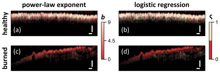
Diagnostic capability of STFT spectral analysis shown by color coding image based on power-law exponent [(a), (c)] or via logistic regression [(b), (d)] for healthy [(a), (c)] and burned tissues [(c), (d)]. Scale bars = 250 μm. [Reprinted with permission from Maher et al., originally published in Optics Letters 39, 5594–5597, (2014).]
Some challenges remain to be addressed before SOCT can be successfully translated to the clinic. These include continuing to develop methods used to separate scattering and absorption coefficients68 and improving the accuracy of hemoglobin concentration and oxygen saturation measurements through careful selection of relevant acquisition properties (e.g., illumination wavelength, illumination power, measurement time) and processing routines. However, taken together, the studies cited above suggest that SOCT is a promising technology for assessing the health and function of biological tissue with many directions for future research.
Molecular imaging in OCT
As discussed above, OCT has found widespread application by measuring microscopic structure with novel extensions providing functional information. However, in contrast to many other medical imaging modalities, OCT does not inherently offer the ability to track molecular species. While spectroscopic OCT has shown the ability to assess biochemical distribution of certain biochemicals, the ability to detect exogenous molecular contrast agents can greatly extend the utility of the approach. Since OCT relies on coherent detection of photons, which have interacted with a sample, it cannot directly detect incoherent fluorescent photons. Instead, these contrast agents must be detected either by observing the absorption associated with their excitation or instead relying on a coherent process to generate photons, which can be interferometrically detected. Finally, molecular contrast can also be generated in OCT by using exogenous agents designed to produce unique scattering features.
Development
The first molecular imaging OCT approaches used spectroscopic OCT to detect the absorption of near infrared (NIR) dyes.85 This preliminary study matched the dye absorption to the spectral band of the OCT light in the 780 nm region. By tracking the centroid of the returned light spectrum using SOCT methods described above, the presence of the dye was revealed. While this approach was simple and easily implemented, the simple absorption profile can be complicated by the presence of scattering, requiring a means for separating the two.68
A later approach by Yang et al.86 developed a spectral triangulation method to detect indocyanine green (ICG). This approach relies on the fact that most scattering profiles present monotonic dependence on wavelength. Thus, the spectrum obtained with SOCT methods can be divided into just a small number of segments to detect the contrast agent and avoid the tradeoff in resolution seen for the STFTs needed for high spectral resolution. As noted above, Robles et al. also used absorption profiles to detect the presence of sodium fluorescein.83 This approach was able to distinguish the contrast agent from other spectral features by obtaining high resolution spectra using the DW approach.71
A different means for discriminating the absorption of a contrast agent can be realized by using a method that actively changes the absorption cross section by optical excitation. This approach termed pump-probe OCT,87 relies on using an optical excitation to cause the contrast agent to transition to a triplet state. While this is usually undesirable for fluorescence imaging, since the contrast agent will temporarily cease to emit, the changes in absorption that are associated with this transition can be detected with OCT if carefully selected. In this demonstration, the triplet absorption cross-section of methylene blue in the 830 nm region overlapped with the spectral band of the OCT system. The limitation of this approach is that the triplet state, while long lived by fluorescence lifetime standards, was sufficiently short to only allow a single OCT scan per pump-probe cycle, resulting in a low efficiency. Later studies using this approach88 extended its utility by employing different contrast agents, such as bacteriorhodopsin and phytochrome A. The contrast agents used in this study used a slightly different mechanism where the absorption shifted depending on the protein state. With one absorption state offering a significantly longer lifetime, this approach did not require high intensity light to cause the transition to the triplet state. However, the limited choice of contrast agents and the long-lived state has limited further applications.
Molecular contrast can also be generated by leveraging nonlinear optical interactions, which generate coherent photons that are coherent with the excitation field. In OCT imaging, the processes of second harmonic generation (SHG) and coherent anti-Stokes Raman (CARS) have both been examined as molecular imaging schemes. SHG appears in media without inversion symmetry and in biomedical imaging, it is particularly useful for imaging collagen structures. Since the SHG light is coherent with the excitation, it can be detected with OCT by generating a reference field that is also at the second harmonic frequency. This approach has been demonstrated by multiple groups89–91 but became less favorable as multimodality imaging that combined OCT with multiphoton microscopy took hold.92 Another nonlinear process, CARS has also been incorporated into OCT imaging93 but the complex scheme has prevented further development and widespread use.
The use of scattering based contrast agents within OCT also offers the possibility for molecular imaging. For example, plasmonic nanoparticles offer distinct optical signatures94 and can be used in place of fluorescent markers.95 Gold nanoparticles have been explored for use in OCT, either through detection of their absorption signature96 or by photothermal excitation97 or both.98 Recent extension to in vivo use in an animal model has shown the potential of gold nanoparticles as an imaging contrast agent but did not demonstrate molecular specificity.99
Clinical applications
Given the early stages of molecular imaging methods in OCT, studies have been limited thus far to animal models. Potential applications of these approaches include detection of neoplastic processes and arterial oxygenation.
Ground-state recovery pump-probe OCT (gsrPPOCT) is an extension of pump-probe OCT that provides molecular specificity with spatial resolution of 10 μm. Applegate and Izatt initially studied gsrPPOCT in the gills of euthanized zebrafish and demonstrated that the gsrPPOCT signal of hemoglobin correlated with OCT images of efferent filament arteries. Arteries were visualized as linear shadows by conventional OCT imaging, which was overlaid with the gsrPPOCT signal to confirm the presence of hemoglobin within these arteries. Limitations of this system included slow line rates of approximately 1 Hz and limited penetration depth due to the short wavelength probe.100
Applegate further developed the approach with a two-color Fourier domain PPOCT system101 that demonstrated imaging depths beyond 725 μm and A-scan rates greater than 1 kHz. This system was used to image an ex vivo porcine eye with the cornea and aqueous humor removed (in order to avoid compensating for the refractive power of the cornea). The porcine iris is rich in eumelanin, which appears as a strong signal on the PPOCT image of the iris (Figure 11).101 This result suggested that PPOCT could be helpful in diagnosis of ocular melanoma, but further work with intact human eyes would need to be demonstrated to warrant clinical translation.
Figure 11.

[a] Biomolecular energy level diagram that shows potential physical processes and how pump-probe spectroscopy may interrogate them. Solid arrows indicate driven transitions by pump (blue) or probe (red, green, cyan). Dashed arrows indicate spontaneous transitions. [b] Schematic of Fourier domain pump-probe OCT system. [c1–c5] OCT image of a porcine lens and iris. [c1] is correlated to a PPOCT image mapping melanin to the iris [c2] and PPOCT image without pump radiation [c3]. The background subtracted PPOCT image [c4] is derived from averaged versions of [c2] and [c3]. [c5] is a reflectivity-independent molecular image on a linear scale where 1 indicates the maximum concentration. Scale bar = 200 μm. [Reprinted with permission from Jacob et al., originaly published in Optics Express 18, 12399-12310 (2010).]
Fluorescence-guided OCT has been employed in identification of malignancy in animal models. Jo et al. incorporated OCT and fluorescence lifetime imaging microscopy (FLIM) into a single system and used it to image oral squamous cell carcinoma in an in vivo hamster model.102 Compared to the control model, lesions in animals with oral cancer had a distinctive FLIM pattern: the central area had a fluorescence characteristic of NADH/FAD while the surrounding area was characteristic of collagen. This multi-modality approach offers good diagnostic potential without the need to directly detect the contrast agent with OCT. However, the depth gating capabilities of OCT are not extended to the molecular specificity with this approach.
Cardiovascular application of fluorescence guided OCT has been explored as well. Liang et al. developed a multimodality fluorescence and optical coherence tomography probe based on a double-clad fiber (DCF) combiner. To evaluate this system, an ex vivo rabbit artery injected with highly saturated grease was stained for annexin V-conjugated Cy 5.5 and imaged. Annexin V is an antibody that targets apoptotic macrophages that accumulate in the core of plaques.103 While the compelling combination of OCT and molecular imaging could offer significant utility, further work is needed for these modalities to be brought to the clinic.
Conclusion
Functional OCT extensions have the potential to extend clinical application of OCT by providing new sources of information about a target tissue, such as blood flow, collagen organization, or oxygenation. Five different types of functional OCT have been discussed here: DOCT, PS-OCT, OCE, SOCT and molecular imaging OCT. The main features and key references for each of these techniques is given in Table 1. The first three techniques in this list have received greater attention in the literature to date due to their further development towards clinical use with researchers having characterized DOCT, PS-OCT, and OCE for in vivo or ex vivo human tissue studies. SOCT and molecular imaging are more recent advances that demonstrate promising results in animal models but have yet to be studied in humans. In particular, molecular imaging carries excellent potential to correlate imaging to disease physiology, as scientists continue to elucidate the biochemical and molecular processes of human disease.
Table 1.
Summary of OCT techniques with their associated principles, applications, and references.
| OCT Technique | Scientific Principle | Clinical Applications | References |
|---|---|---|---|
| Doppler | Speed of a moving particle is measured by detecting frequency shifts of the light scattered by the particle. |
|
|
| Polarization-sensitive | Sample is exposed to light from multiple polarizations to measure birefringence. |
|
|
| Elastography | External deformation of the sample is introduced to measure strain and elastic modulus of tissue. |
|
|
| Spectroscopic | Wavelength-dependent absorption and light scattering is used to elucidate function. |
|
|
| Molecular | Light is absorbed by biomarkers in tissue, and absorption changes as the molecular environment changes |
|
The promise of OCT as an “optical biopsy” has the potential to transform the traditional paradigm of medical diagnostics, which currently relies on histopathology and macro-scale imaging such as computed tomography. Integration and validation of functional OCT extensions will make OCT an even more important technology for the future: by providing in vivo, high-resolution information about diseased tissue in a noninvasive fashion, it fulfills a clinical need that has not been addressed previously.
Acknowledgments
We acknowledge funding support from NSF (CBET-1445992) the National Eye Institute (1R21EY023451), as well as an Innovative Ophthalmic Research award from Research to Prevent Blindness
References
- 1.Huang D, et al. Optical Coherence Tomography. Science. 1991;254:1178–1181. doi: 10.1126/science.1957169. [DOI] [PMC free article] [PubMed] [Google Scholar]
- 2.Izatt JA, et al. Optical coherence tomography for biodiagnostics. Optics and Photonics News. 1997;8:41. [Google Scholar]
- 3.Tearney GJ, et al. In vivo endoscopic optical biopsy with optical coherence tomography. Science. 1997;276:2037–2039. doi: 10.1126/science.276.5321.2037. [DOI] [PubMed] [Google Scholar]
- 4.Hee MR, et al. Optical coherence tomography of the human retina. Archives of ophthalmology. 1995;113:325–332. doi: 10.1001/archopht.1995.01100030081025. [DOI] [PubMed] [Google Scholar]
- 5.Vakoc BJ, Fukumura D, Jain RK, Bouma BE. Cancer imaging by optical coherence tomography: preclinical progress and clinical potential. Nature Reviews Cancer. 2012;12:363–368. doi: 10.1038/nrc3235. [DOI] [PMC free article] [PubMed] [Google Scholar]
- 6.Zysk AM, Nguyen FT, Oldenburg AL, Boppart SA, Marks DL. Optical coherence tomography: a review of clinical development from bench to bedside. Journal of biomedical optics. 2007;12 doi: 10.1117/1.2793736. 051403-051403-051421. [DOI] [PubMed] [Google Scholar]
- 7.Izatt JA, Kulkarni MD, Wang HW, Kobayashi K, Sivak MV., Jr Optical coherence tomography and microscopy in gastrointestinal tissues. Selected Topics in Quantum Electronics, IEEE Journal of. 1996;2:1017–1028. [Google Scholar]
- 8.Drexler W, et al. Optical coherence tomography today: speed, contrast, and multimodality. Journal of biomedical optics. 2014;19:071412–071412. doi: 10.1117/1.JBO.19.7.071412. [DOI] [PubMed] [Google Scholar]
- 9.Drexler W, Fujimoto JG. Optical coherence tomography: technology and applications. Springer Science & Business Media; 2008. [Google Scholar]
- 10.Liu G, Chen Z. Phase-Resolved Doppler Optical Coherence Tomography. INTECH Open Access Publisher; 2012. [Google Scholar]
- 11.Liu G, Lin AJ, Tromberg BJ, Chen Z. A comparison of Doppler optical coherence tomography methods. Biomedical optics express. 2012;3:2669–2680. doi: 10.1364/BOE.3.002669. [DOI] [PMC free article] [PubMed] [Google Scholar]
- 12.Yang V, et al. High speed, wide velocity dynamic range Doppler optical coherence tomography (Part I): System design, signal processing, and performance. Optics Express. 2003;11:794–809. doi: 10.1364/oe.11.000794. [DOI] [PubMed] [Google Scholar]
- 13.Yang VX, et al. High speed, wide velocity dynamic range Doppler optical coherence tomography (Part II): Imaging in vivo cardiac dynamics of Xenopus laevis. Optics Express. 2003;11:1650–1658. doi: 10.1364/oe.11.001650. [DOI] [PubMed] [Google Scholar]
- 14.Larina IV, Furushima K, Dickinson ME, Behringer RR, Larin KV. Live imaging of rat embryos with Doppler swept-source optical coherence tomography. J Biomed Opt. 2009;14:050506. doi: 10.1117/1.3241044. [DOI] [PMC free article] [PubMed] [Google Scholar]
- 15.Peterson LM, et al. 4D shear stress maps of the developing heart using Doppler optical coherence tomography. Biomedical optics express. 2012;3:3022–3032. doi: 10.1364/BOE.3.003022. [DOI] [PMC free article] [PubMed] [Google Scholar]
- 16.Hendargo HC, McNabb RP, Dhalla A-H, Shepherd N, Izatt JA. Doppler velocity detection limitations in spectrometer-based versus swept-source optical coherence tomography. Biomedical Optics Express. 2011;2:2175–2188. doi: 10.1364/BOE.2.002175. [DOI] [PMC free article] [PubMed] [Google Scholar]
- 17.Wang Y, et al. Pilot study of optical coherence tomography measurement of retinal blood flow in retinal and optic nerve diseases. Investigative ophthalmology & visual science. 2011;52:840–845. doi: 10.1167/iovs.10-5985. [DOI] [PMC free article] [PubMed] [Google Scholar]
- 18.Wang RK, et al. Three dimensional optical angiography. Opt Express. 2007;15:4083–4097. doi: 10.1364/oe.15.004083. [DOI] [PubMed] [Google Scholar]
- 19.Fingler J, Schwartz D, Yang C, Fraser SE. Mobility and transverse flow visualization using phase variance contrast with spectral domain optical coherence tomography. Optics Express. 2007;15:12636–12653. doi: 10.1364/OE.15.012636. [DOI] [PubMed] [Google Scholar]
- 20.Mariampillai A, et al. Speckle variance detection of microvasculature using swept-source optical coherence tomography. Optics Letters. 2008;33:1530–1532. doi: 10.1364/OL.33.001530. [DOI] [PubMed] [Google Scholar]
- 21.Hendargo HC, et al. Automated non-rigid registration and mosaicing for robust imaging of distinct retinal capillary beds using speckle variance optical coherence tomography. Biomedical optics express. 2013;4:803–821. doi: 10.1364/BOE.4.000803. [DOI] [PMC free article] [PubMed] [Google Scholar]
- 22.Yazdanfar S, Rollins AM, Izatt JA. In vivo imaging of human retinal flow dynamics by color Doppler optical coherence tomography. Archives of Ophthalmology. 2003;121:235–239. doi: 10.1001/archopht.121.2.235. [DOI] [PubMed] [Google Scholar]
- 23.White B, et al. In vivo dynamic human retinal blood flow imaging using ultra-high-speed spectral domain optical coherence tomography. Optics Express. 2003;11:3490–3497. doi: 10.1364/oe.11.003490. [DOI] [PubMed] [Google Scholar]
- 24.Yang VX, et al. Endoscopic Doppler optical coherence tomography in the human GI tract: initial experience. Gastrointestinal endoscopy. 2005;61:879–890. doi: 10.1016/s0016-5107(05)00323-8. [DOI] [PubMed] [Google Scholar]
- 25.Wierwille J, et al. In vivo, label-free, three-dimensional quantitative imaging of kidney microcirculation using Doppler optical coherence tomography. Laboratory investigation. 2011;91:1596–1604. doi: 10.1038/labinvest.2011.112. [DOI] [PMC free article] [PubMed] [Google Scholar]
- 26.Andrews PM, Chen Y. Using Optical Coherence Tomography (OCT) to Evaluate Human Donor Kidneys Prior to and Following Transplantation. J Nephrol Ther. 2014;4 2161-0959.1000151. [Google Scholar]
- 27.Otis LL, Piao D, Gibson CW, Zhu Q. Quantifying labial blood flow using optical Doppler tomography. Oral Surgery, Oral Medicine, Oral Pathology, Oral Radiology, and Endodontology. 2004;98:189–194. doi: 10.1016/j.tripleo.2004.03.030. [DOI] [PubMed] [Google Scholar]
- 28.Zhao Y, et al. Three-dimensional reconstruction of in vivo blood vessels in human skin using phase-resolved optical Doppler tomography. Selected Topics in Quantum Electronics, IEEE Journal of. 2001;7:931–935. [Google Scholar]
- 29.Zhao Y, et al. Phase-resolved optical coherence tomography and optical Doppler tomography for imaging blood flow in human skin with fast scanning speed and high velocity sensitivity. Optics letters. 2000;25:114–116. doi: 10.1364/ol.25.000114. [DOI] [PubMed] [Google Scholar]
- 30.Hee MR, Huang D, Swanson EA, Fujimoto JG. Polarization-sensitive low-coherence reflectometer for birefringence characterization and ranging. J Opt Soc Am B. 1992;9:903–908. doi: 10.1364/JOSAB.9.000903. [DOI] [Google Scholar]
- 31.de Boer JF, Milner TE, van Gemert MJC, Nelson JS. Two-dimensional birefringence imaging in biological tissue by polarization-sensitive optical coherence tomography. Optics Letters. 1997;22:934–936. doi: 10.1364/OL.22.000934. [DOI] [PubMed] [Google Scholar]
- 32.de Boer JF, Milner TE, Nelson JS. Determination of the depth-resolved Stokes parameters of light backscattered from turbid media by use of polarization-sensitive optical coherence tomography. Optics Letters. 1999;24:300–302. doi: 10.1364/OL.24.000300. [DOI] [PubMed] [Google Scholar]
- 33.Saxer CE, et al. High-speed fiber based polarization-sensitive optical coherence tomography of in vivo human skin. Optics Letters. 2000;25:1355–1357. doi: 10.1364/OL.25.001355. [DOI] [PubMed] [Google Scholar]
- 34.Pircher M, Goetzinger E, Leitgeb R, Hitzenberger C. Three dimensional polarization sensitive OCT of human skin in vivo. Optics express. 2004;12:3236–3244. doi: 10.1364/opex.12.003236. [DOI] [PubMed] [Google Scholar]
- 35.Pircher M, Goetzinger E, Leitgeb R, Hitzenberger CK. Transversal phase resolved polarization sensitive optical coherence tomography. Physics in medicine and biology. 2004;49:1257. doi: 10.1088/0031-9155/49/7/013. [DOI] [PubMed] [Google Scholar]
- 36.Choma M, Sarunic M, Yang C, Izatt J. Sensitivity advantage of swept source and Fourier domain optical coherence tomography. Optics Express. 2003;11:2183–2189. doi: 10.1364/oe.11.002183. [DOI] [PubMed] [Google Scholar]
- 37.Götzinger E, Pircher M, Hitzenberger CK. High speed spectral domain polarization sensitive optical coherence tomography of the human retina. Optics express. 2005;13:10217–10229. doi: 10.1364/OPEX.13.010217. [DOI] [PMC free article] [PubMed] [Google Scholar]
- 38.Yamanari M, Makita S, Madjarova VD, Yatagai T, Yasuno Y. Fiber-based polarization-sensitive Fourier domain optical coherence tomography using B-scan-oriented polarization modulation method. Optics Express. 2006;14:6502–6515. doi: 10.1364/OE.14.006502. [DOI] [PubMed] [Google Scholar]
- 39.Yamanari M, Makita S, Yasuno Y. Polarization-sensitive swept-source optical coherence tomography with continuous source polarization modulation. Optics express. 2008;16:5892–5906. doi: 10.1364/OE.16.005892. [DOI] [PubMed] [Google Scholar]
- 40.Oh WY, et al. High-speed polarization sensitive optical frequency domain imaging with frequency multiplexing. Optics Express. 2008;16:1096–1103. doi: 10.1364/OE.16.001096. [DOI] [PMC free article] [PubMed] [Google Scholar]
- 41.Baumann B, et al. Swept source/Fourier domain polarization sensitive optical coherence tomography with a passive polarization delay unit. Optics express. 2012;20:10229–10241. doi: 10.1364/OE.20.010229. [DOI] [PMC free article] [PubMed] [Google Scholar]
- 42.Lammer J, et al. Detection and Analysis of Hard Exudates by Polarization-Sensitive Optical Coherence Tomography in Patients With Diabetic Maculopathy. Investigative ophthalmology & visual science. 2014;55:1564–1571. doi: 10.1167/iovs.13-13539. [DOI] [PubMed] [Google Scholar]
- 43.Pierce MC, Sheridan RL, Hyle Park B, Cense B, de Boer JF. Collagen denaturation can be quantified in burned human skin using polarization-sensitive optical coherence tomography. Burns. 2004;30:511–517. doi: 10.1016/j.burns.2004.02.004. [DOI] [PubMed] [Google Scholar]
- 44.Drexler W, et al. Correlation of collagen organization with polarization sensitive imaging of in vitro cartilage: implications for osteoarthritis. The Journal of rheumatology. 2001;28:1311–1318. [PubMed] [Google Scholar]
- 45.Baumgartner A, et al. Polarization-sensitive optical coherence tomography of dental structures. Caries Res. 2000;34:59–69. doi: 10.1159/000016571. [DOI] [PubMed] [Google Scholar]
- 46.Li Y, Snedeker J. Elastography: modality-specific approaches, clinical applications, and research horizons. Skeletal Radiol. 2011;40:389–397. doi: 10.1007/s00256-010-0918-0. [DOI] [PubMed] [Google Scholar]
- 47.Lerner R, Parker K, Holen J, Gramiak R, Waag R. In: Acoustical Imaging Vol. 16 Acoustical Imaging. Kessler Lawrence W., editor. Ch 31. Springer; US: 1988. pp. 317–327. [Google Scholar]
- 48.Muthupillai R, et al. Magnetic resonance elastography by direct visualization of propagating acoustic strain waves. Science. 1995;269:1854–1857. doi: 10.1126/science.7569924. [DOI] [PubMed] [Google Scholar]
- 49.Schmitt J. OCT elastography: imaging microscopic deformation and strain of tissue. Optics express. 1998;3:199–211. doi: 10.1364/oe.3.000199. [DOI] [PubMed] [Google Scholar]
- 50.Adie SG, et al. Spectroscopic optical coherence elastography. Optics express. 2010;18:25519–25534. doi: 10.1364/OE.18.025519. [DOI] [PMC free article] [PubMed] [Google Scholar]
- 51.Liang X, Adie SG, John R, Boppart SA. Dynamic spectral-domain optical coherence elastography for tissue characterization. Optics express. 2010;18:14183–14190. doi: 10.1364/OE.18.014183. [DOI] [PMC free article] [PubMed] [Google Scholar]
- 52.Kennedy BF, et al. In vivo three-dimensional optical coherence elastography. Optics express. 2011;19:6623. doi: 10.1364/OE.19.006623. [DOI] [PMC free article] [PubMed] [Google Scholar]
- 53.Kennedy KM, et al. Needle optical coherence elastography for the measurement of microscale mechanical contrast deep within human breast tissues. J Biomed Opt. 2013;18 doi: 10.1117/1.JBO.18.12.121510. 121510-121510. [DOI] [PubMed] [Google Scholar]
- 54.Sun C, Standish B, Yang VXD. Optical coherence elastography: current status and future applications. J Biomed Opt. 2011;16 doi: 10.1117/1.3560294. 043001-043001-043012. [DOI] [PubMed] [Google Scholar]
- 55.Chan R, et al. OCT-based arterial elastography: robust estimation exploiting tissue biomechanics. Optics Express. 2004;12:4558–4572. doi: 10.1364/opex.12.004558. [DOI] [PubMed] [Google Scholar]
- 56.Davies M. Anatomic features in victims of sudden coronary death. Coronary artery pathology. Circulation. 1992;85:I19–24. [PubMed] [Google Scholar]
- 57.Fujii K, et al. Frequency and Predictor of Coronary Thin-Cap Fibroatheroma in Patients With Acute Myocardial Infarction and Stable Angina PectorisA 3-Vessel Optical Coherence Tomography Study. Journal of the American College of Cardiology. 2008;52:787–788. doi: 10.1016/j.jacc.2008.05.030. [DOI] [PubMed] [Google Scholar]
- 58.Jang IK, et al. In vivo characterization of coronary atherosclerotic plaque by use of optical coherence tomography. Circulation. 2005;111:1551–1555. doi: 10.1161/01.CIR.0000159354.43778.69. [DOI] [PMC free article] [PubMed] [Google Scholar]
- 59.Kubo T, et al. Assessment of Culprit Lesion Morphology in Acute Myocardial Infarction Ability of Optical Coherence Tomography Compared With Intravascular Ultrasound and Coronary Angioscopy. Journal of the American College of Cardiology. 2007;50:933–939. doi: 10.1016/j.jacc.2007.04.082. [DOI] [PubMed] [Google Scholar]
- 60.Stone GW, et al. A prospective natural-history study of coronary atherosclerosis. New England Journal of Medicine. 2011;364:226–235. doi: 10.1056/NEJMoa1002358. [DOI] [PubMed] [Google Scholar]
- 61.Virmani R, Burke AP, Kolodgie FD, Farb A. Pathology of the Thin - Cap Fibroatheroma. Journal of interventional cardiology. 2003;16:267–272. doi: 10.1034/j.1600-0854.2003.8042.x. [DOI] [PubMed] [Google Scholar]
- 62.Oldenburg AL, et al. Imaging and elastometry of blood clots using magnetomotive optical coherence tomography and labeled platelets. Selected Topics in Quantum Electronics, IEEE Journal of. 2012;18:1100–1109. doi: 10.1109/JSTQE.2011.2162580. [DOI] [PMC free article] [PubMed] [Google Scholar]
- 63.Chhetri RK, Carpenter J, Superfine R, Randell SH, Oldenburg AL. BiOS. International Society for Optics and Photonics; 755420-755420-755410. [Google Scholar]
- 64.Ford MR, Roy AS, Rollins AM, Dupps WJ., Jr Serial biomechanical comparison of edematous, normal, and collagen crosslinked human donor corneas using optical coherence elastography. Journal of Cataract & Refractive Surgery. 2014;40:1041–1047. doi: 10.1016/j.jcrs.2014.03.017. [DOI] [PMC free article] [PubMed] [Google Scholar]
- 65.Liang X, Boppart SA. Biomechanical properties of in vivo human skin from dynamic optical coherence elastography. Biomedical Engineering, IEEE Transactions on. 2010;57:953–959. doi: 10.1109/TBME.2009.2033464. [DOI] [PMC free article] [PubMed] [Google Scholar]
- 66.Srivastava A, Verma Y, Rao K, Gupta P. Determination of elastic properties of resected human breast tissue samples using optical coherence tomographic elastography. Strain. 2011;47:75–87. [Google Scholar]
- 67.Morgner U, et al. Spectroscopic optical coherence tomography. Opt Lett. 2000;25:111–113. doi: 10.1364/ol.25.000111. [DOI] [PubMed] [Google Scholar]
- 68.Robles FE, Wax A. Separating the scattering and absorption coefficients using the real and imaginary parts of the refractive index with low-coherence interferometry. Optics Letters. 2010;35:2843–2845. doi: 10.1364/OL.35.002843. [DOI] [PMC free article] [PubMed] [Google Scholar]
- 69.Robles FE, Wax A. Measuring morphological features using light-scattering spectroscopy and Fourier-domain low-coherence interferometry. Optics Letters. 2010;35:360–362. doi: 10.1364/OL.35.000360. [DOI] [PMC free article] [PubMed] [Google Scholar]
- 70.Graf RN, Wax A. Temporal coherence and time-frequency distributions in spectroscopic optical coherence tomography. Journal of the Optical Society of America. A, Optics, image science, and vision. 2007;24:2186–2195. doi: 10.1364/josaa.24.002186. [DOI] [PMC free article] [PubMed] [Google Scholar]
- 71.Robles F, Graf RN, Wax A. Dual window method for processing spectroscopic optical coherence tomography signals with simultaneously high spectral and temporal resolution. Optics express. 2009;17:6799–6812. doi: 10.1364/oe.17.006799. [DOI] [PMC free article] [PubMed] [Google Scholar]
- 72.Bosschaart N, van Leeuwen TG, Aalders MCG, Faber DJ. Quantitative comparison of analysis methods for spectroscopic optical coherence tomography. Biomedical Optics Express. 2013;4:2570–2584. doi: 10.1364/boe.4.002570. [DOI] [PMC free article] [PubMed] [Google Scholar]
- 73.Maher JR, et al. In vivo analysis of burns in a mouse model using spectroscopic optical coherence tomography. Optics Letters. 2014;39:5594–5597. doi: 10.1364/OL.39.005594. [DOI] [PMC free article] [PubMed] [Google Scholar]
- 74.Graf RN, Robles FE, Chen X, Wax A. Detecting precancerous lesions in the hamster cheek pouch using spectroscopic white-light optical coherence tomography to assess nuclear morphology via spectral oscillations. Journal of biomedical optics. 2009;14 doi: 10.1117/1.3269680. 064030-064030-064038. [DOI] [PMC free article] [PubMed] [Google Scholar]
- 75.Robles FE, Zhu Y, Lee J, Sharma S, Wax A. Detection of early colorectal cancer development in the azoxymethane rat carcinogenesis model with Fourier domain low coherence interferometry. Biomed Opt Express. 2010;1:736–745. doi: 10.1364/BOE.1.000736. [DOI] [PMC free article] [PubMed] [Google Scholar]
- 76.Xu CY, Kamalabadi F, Boppart SA. Comparative performance analysis of time-frequency distributions for spectroscopic optical coherence tomography. Applied Optics. 2005;44:1813–1822. doi: 10.1364/Ao.44.001813. [DOI] [PubMed] [Google Scholar]
- 77.Faber DJ, Mik EG, Aalders MC, van Leeuwen TG. Light absorption of (oxy-) hemoglobin assessed by spectroscopic optical coherence tomography. Optics letters. 2003;28:1436–1438. doi: 10.1364/ol.28.001436. [DOI] [PubMed] [Google Scholar]
- 78.Faber DJ, Mik EG, Aalders MC, van Leeuwen TG. Toward assessment of blood oxygen saturation by spectroscopic optical coherence tomography. Optics letters. 2005;30:1015–1017. doi: 10.1364/ol.30.001015. [DOI] [PubMed] [Google Scholar]
- 79.Lu C-W, Lee C-K, Tsai M-T, Wang Y-M, Yang CC. Measurement of the hemoglobin oxygen saturation level with spectroscopic spectral-domain optical coherence tomography. Optics Letters. 2008;33:416–418. doi: 10.1364/OL.33.000416. [DOI] [PubMed] [Google Scholar]
- 80.Liu X, Kang JU. Depth-resolved blood oxygen saturation assessment using spectroscopic common-path Fourier domain optical coherence tomography. Biomedical Engineering, IEEE Transactions on. 2010;57:2572–2575. doi: 10.1109/TBME.2010.2058109. [DOI] [PMC free article] [PubMed] [Google Scholar]
- 81.Yi J, Li X. Estimation of oxygen saturation from erythrocytes by high-resolution spectroscopic optical coherence tomography. Optics Letters. 2010;35:2094–2096. doi: 10.1364/OL.35.002094. [DOI] [PubMed] [Google Scholar]
- 82.Robles FE, Chowdhury S, Wax A. Assessing hemoglobin concentration using spectroscopic optical coherence tomography for feasibility of tissue diagnostics. Biomed Opt Express. 2010;1:310–317. doi: 10.1364/boe.1.000310/. [DOI] [PMC free article] [PubMed] [Google Scholar]
- 83.Robles FE, Wilson C, Grant G, Wax A. Molecular imaging true-colour spectroscopic optical coherence tomography. Nature Photonics. 2011;5:744–747. doi: 10.1038/nphoton.2011.257. http://www.nature.com/nphoton/journal/v5/n12/abs/nphoton.2011.257.html-supplementary-information. [DOI] [PMC free article] [PubMed] [Google Scholar]
- 84.Fleming CP, Eckert J, Halpern EF, Gardecki JA, Tearney GJ. Depth resolved detection of lipid using spectroscopic optical coherence tomography. Biomedical optics express. 2013;4:1269–1284. doi: 10.1364/BOE.4.001269. [DOI] [PMC free article] [PubMed] [Google Scholar]
- 85.Xu C, Ye J, Marks DL, Boppart SA. Near-infrared dyes as contrast-enhancing agents for spectroscopic optical coherence tomography. Optics letters. 2004;29:1647–1649. doi: 10.1364/ol.29.001647. [DOI] [PubMed] [Google Scholar]
- 86.Yang C, et al. Spectral triangulation molecular contrast optical coherence tomography with indocyanine green as the contrast agent. Optics Letters. 2004;29:2016–2018. doi: 10.1364/ol.29.002016. [DOI] [PMC free article] [PubMed] [Google Scholar]
- 87.Rao KD, Choma MA, Yazdanfar S, Rollins AM, Izatt JA. Molecular contrast in optical coherence tomography by use of a pump probe technique. Optics letters. 2003;28:340–342. doi: 10.1364/ol.28.000340. [DOI] [PubMed] [Google Scholar]
- 88.Yang C, Choma MA, Lamb LE, Simon JD, Izatt JA. Protein-based molecular contrast optical coherence tomography with phytochrome as the contrast agent. Optics letters. 2004;29:1396–1398. doi: 10.1364/ol.29.001396. [DOI] [PubMed] [Google Scholar]
- 89.Jiang Y, Tomov I, Wang Y, Chen Z. Second-harmonic optical coherence tomography. Optics letters. 2004;29:1090–1092. doi: 10.1364/ol.29.001090. [DOI] [PubMed] [Google Scholar]
- 90.Applegate BE, Yang C, Rollins AM, Izatt JA. Polarization-resolved second-harmonic-generation optical coherence tomography in collagen. Optics letters. 2004;29:2252–2254. doi: 10.1364/ol.29.002252. [DOI] [PubMed] [Google Scholar]
- 91.Yazdanfar S, Laiho L, So P. Interferometric second harmonic generation microscopy. Optics express. 2004;12:2739–2745. doi: 10.1364/opex.12.002739. [DOI] [PubMed] [Google Scholar]
- 92.Chong SP, Lai T, Zhou Y, Tang S. Tri-modal microscopy with multiphoton and optical coherence microscopy/tomography for multi-scale and multi-contrast imaging. Biomedical optics express. 2013;4:1584–1594. doi: 10.1364/BOE.4.001584. [DOI] [PMC free article] [PubMed] [Google Scholar]
- 93.Bredfeldt JS, Vinegoni C, Marks DL, Boppart SA. Molecularly sensitive optical coherence tomography. Optics Letters. 2005;30:495–497. doi: 10.1364/ol.30.000495. [DOI] [PubMed] [Google Scholar]
- 94.Wax A, Sokolov K. Molecular imaging and darkfield microspectroscopy of live cells using gold plasmonic nanoparticles. Laser & Photonics Reviews. 2009;3:146–158. [Google Scholar]
- 95.Crow MJ, Grant G, Provenzale JM, Wax A. Molecular imaging and quantitative measurement of epidermal growth factor receptor expression in live cancer cells using immunolabeled gold nanoparticles. American Journal of Roentgenology. 2009;192:1021–1028. doi: 10.2214/AJR.07.3535. [DOI] [PubMed] [Google Scholar]
- 96.Li YL, Seekell K, Yuan H, Robles FE, Wax A. Multispectral nanoparticle contrast agents for true-color spectroscopic optical coherence tomography. Biomedical optics express. 2012;3:1914–1923. doi: 10.1364/BOE.3.001914. [DOI] [PMC free article] [PubMed] [Google Scholar]
- 97.Skala MC, Crow MJ, Wax A, Izatt JA. Photothermal optical coherence tomography of epidermal growth factor receptor in live cells using immunotargeted gold nanospheres. Nano letters. 2008;8:3461–3467. doi: 10.1021/nl802351p. [DOI] [PMC free article] [PubMed] [Google Scholar]
- 98.Nahas A, Varna M, Fort E, Boccara AC. Detection of plasmonic nanoparticles with full field-OCT: optical and photothermal detection. Biomedical Optics Express. 2014;5:3541–3546. doi: 10.1364/boe.5.003541. [DOI] [PMC free article] [PubMed] [Google Scholar]
- 99.Tucker-Schwartz JM, et al. In vivo imaging of nanoparticle delivery and tumor microvasculature with multimodal optical coherence tomography. Biomedical Optics Express. 2014;5:1731–1743. doi: 10.1364/boe.5.001731. [DOI] [PMC free article] [PubMed] [Google Scholar]
- 100.Applegate BE, Izatt JA. Molecular imaging of endogenous and exogenous chromophores using ground state recovery pump-probe optical coherence tomography. Optics express. 2006;14:9142–9155. doi: 10.1364/oe.14.009142. [DOI] [PubMed] [Google Scholar]
- 101.Jacob D, Shelton RL, Applegate BE. Fourier domain pump-probe optical coherence tomography imaging of Melanin. Optics express. 2010;18:12399–12410. doi: 10.1364/OE.18.012399. [DOI] [PMC free article] [PubMed] [Google Scholar]
- 102.Jo JA, et al. In vivo simultaneous morphological and biochemical optical imaging of oral epithelial cancer. Biomedical Engineering, IEEE Transactions on. 2010;57:2596–2599. doi: 10.1109/TBME.2010.2060485. [DOI] [PMC free article] [PubMed] [Google Scholar]
- 103.Liang S, et al. Intravascular atherosclerotic imaging with combined fluorescence and optical coherence tomography probe based on a double-clad fiber combiner. Journal of biomedical optics. 2012;17:0705011–0705013. doi: 10.1117/1.JBO.17.7.070501. [DOI] [PMC free article] [PubMed] [Google Scholar]
- 104.Larina IV, Furushima K, Dickinson ME, Behringer RR, Larin KV. Live imaging of rat embryos with Doppler swept-source optical coherence tomography. Journal of biomedical optics. 2009;14 doi: 10.1117/1.3241044. 050506-050506-050503. [DOI] [PMC free article] [PubMed] [Google Scholar]