Abstract
Monolithic (single layer) glass-ceramic restorations often fail from chipping and fracture. Using blunt indentation of a model flat porcelain-like brittle layer bonded onto a dentin-like polymer support system, a variety of fatigue fracture modes has been identified and analyzed: outer cone, inner cone, and median cracks developing in the near-contact region at the occlusal surface; radial cracks developing at the internal cementation surface along the loading axis. Our findings indicate that monolithic glass-ceramic layers are vulnerable to both occlusal surface damage and cementation internal surface fracture. Clinical issues in the longevity of ceramic restorations are discussed in relation to biting force, physical properties of ceramic crowns and luting cement, and thicknesses of ceramic and cement layers.
Keywords: Fatigue loading, occlusal cone fracture, cementation radial fracture, layered ceramic structures
I. Introduction
Interest in dental partial fixed all-ceramic prostheses is mainly driven by their excellent properties such as aesthetics and bioinertness. However, the full potential of ceramic restorations has not been realized because of concerns of clinical longevity—ceramic materials are inherently brittle and thus are highly susceptible to catastrophic fracture. Although there has been an immense amount of study concerning the fracture of ceramic crowns, the bulk of these studies has been focusing on load-to-fracture “crunch the crown” tests under monotonic loading where applied load increases with time at a constant rate.1,2 Unfortunately, these crunch the crown/bridge tests often fail to successfully predict the clinical performance of ceramic restorations by over estimating the longevity, because (1) dental ceramics are susceptible to moisture assisted, stress corrosion driven slow crack growth (SCG) which could result in a continued reduction in initial strength over years,3 upon which (2) cumulative mechanical damage may be superimposed.4,5
Monolithic (single layer) glass-ceramic restorative materials have excellent aesthetics based on their translucency, but possess relatively low strength. Therefore, they are indicated for anterior restorations which are subjected to lower biting forces.6 It is generally believed that low strength glass-ceramics require substantial thickness (typically between 1.5 mm to 2 mm) to bear tensile stresses at the cementation internal surface induced by flexure of the crowns under occlusal loading. While tensile stress activated flexural radial cracking at the ceramic internal (cementation) surface remains as an important mechanism of bulk fracture of ceramic crowns (flexural radial cracks originate at the cementation internal surface and propagate upward to the occlusal surface and outward to the margins),7,8 other damage modes induced from the contact stresses at the occlusal surface can occur and can also have the potential to propagate down to the crown/cement interface, resulting in failure of the restorations.
In this paper, we focus on various damage modes incurred in a flat brittle layer bonded to a compliant substrate loaded with a spherical indenter under single- or multi-cycle (fatigue) loading in water. Glass plate is used as a model material because it is transparent, thus permitting in-situ observation of crack initiation and propagation. The current ball-on-flat layer (Hertzian indentation) test, while simplistic, captures the essential elements of the occlusal function and is amenable to explicit fracture mechanics and damage analysis. The principle goal is to understand the role of key variables—biting force, physical properties of ceramic crowns and luting cement, and thicknesses of ceramic and cement layers—in the longevity of ceramic restorations. As we gain a solid understanding of the transparent, flat-layer systems, we are gradually introducing complexities in ceramic microstructures, specimen geometries, loading conditions, and eventually evolving into actual tooth/crown testing (Fig. 1).
Figure 1.
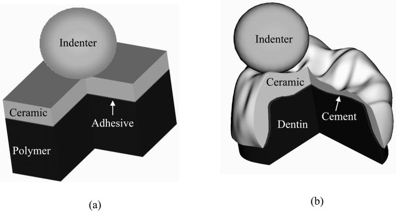
Schematic showing evolution from (a) model ball on flat layer tests to (b) actual dental crown morphology.
II. Background
Intense research concerning the damage modes in brittle coatings on compliant substrates loaded on the top surface—emulating ceramic crowns on dentin—began in the late 1980s.1,9-14 Most of the studies were conducted using single-cycle loading tests. Several fracture modes have been identified and quantified. Near-contact occlusal surface fracture modes, including outer Hertzian cone (O) cracks 15-17 and median (M) cracks, formed from the precursor quasiplastic yield (Y).18-20 Outer cone cracks initiate just outside the indenter contact area where the maximum tensile stress of the Hertizan stress field occurs, and have an angle α ≈ 22° relative to the specimen surface (Fig. 2a). Yield forms beneath the indenter, producing a diffuse subsurface zone of microscopic shear cracks or faults which coalesce and evolve into occlusal surface median cracks (Fig. 2a).19,21-23 For typical brittle materials, such as porcelain, glass, and alumina, median cracks can be produced by a sharp indenter (Vickers or Berkovich or the more recent cubic indenter) at loads P < 10 N. However much higher loads (P > 100 N) are required when a blunt indenter (r > 1 mm, pertinent to antagonistic occlusal contact condition) is used.24,25
Figure 2.
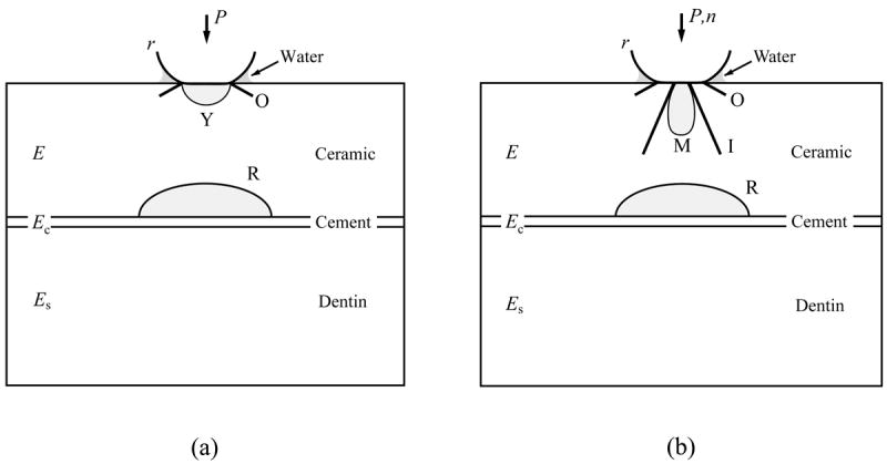
Schematic illustration of damage modes in flat ceramic coatings on compliant substrates with sphere of radius r at load P in water for (a) single-cycle loading and (b) multi-cycle loading. Note: O, outer cone cracks; Y, yield; I, inner cone cracks; M, median cracks; R, radial cracks.
For a ceramic layer uniformly supported by and bonded to a less stiff material such as tooth dentin or dentin substitute composite, tensile stresses develop in the ceramic at the interface with the cement, directly below the load (Fig. 2a). If the tensile stress exceeds the bulk strength of the ceramic layer, an internal surface flexural radial crack (R) can form—very much like subjecting a ceramic bar or disc to a three-point-bend test or a biaxial flexural test, except here we take additional consideration of the supporting role of a dentin-like base. Radial cracks are oriented normal to the plate surface and are therefore susceptible to any flexural tensile stresses generated during occlusion. Once the flexural radial cracks form, the brittle layer becomes virtually disfunctional, especially when the ceramic layer is thin (≤1 mm) or is in a curved geometry where the radial cracks quickly propagate upward to the occlusal surface and outward to the margins.26,27 In dentistry, radial cracks are clinically evidenced as bulk fracture.28
The relative dominance of outer cone fracture and quasiplastic yield in ceramics under single-cycle loading, for indenter radii r between 1 mm and 10 mm (pertinent to dentistry), is determined by the materials properties (Appendix, Eqs. 1 - 3): outer cone fracture tends to dominate in materials with large hardness/modulus and hardness/toughness ratios (brittle), while quasiplastic yield is more dominant in materials with low hardness/modulus and hardness/toughness ratios (quasiplastic).20 Examples of critical loads for the onset of cone fracture and yield for commonly used dental ceramics corresponding to a tungsten carbide indenter (r = 3.18 mm) are shown in Fig. 3. The manufacturer, composition, and physical properties of the dental ceramics investigated are tabulated in Table 1. As can be seen, for the more brittle ceramics like porcelain, outer cone cracks are the predominant damage mode in single-cycle loading.
Figure 3.
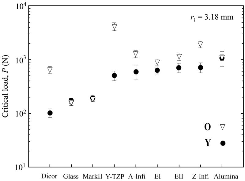
Critical loads and standard deviations for onset of contact damage under single-cycle loading in various dental ceramics, including: Dicor, glass, porcelain (Mark II), zirconia (Y-TZP), glass infiltrated alumina (Inceram alumina, A-Infi), Empress I (EI), Empress II (EII), glass infiltrated zirconia (Inceram zirconia, Z-Infi), and alumina. The composition, manufacturer, and material properties of these dental ceramics and glass are summarized in Table 1. Note: O, outer cone cracks; Y, yield.
Table I.
Properties of relevant materials.a
| Material | Manufacturer | Modulus E (GPa) | Hardness H (GPa) | Toughness T (MPa m1/2) | Flexural Strength S (MPa) |
|---|---|---|---|---|---|
| Glass (soda-lime, abraded) | Daigger | 70 | 5.2 | 0.7 | 110 |
| Feldspathic porcelain (Vita Mark II) | Vita Zahnfabrik | 68 | 6.2 | 0.9 | 130 |
| Mica glass-ceramic (Dicor MGC) | Dentsply | 69 | 3.8 | 1.2 | 110 |
| Leucite glass-ceramic (Empress I) | Ivoclar-Vivadent | 67-86 | 5.6-5.9 | 1.2-1.4 | 160 |
| Lithium disilicate glass-ceramic (Empress II) | Ivoclar-Vivadent | 96 | 5.5-6.3 | 2.9-3.2 | 420 |
| Glass-infiltrated alumina (InCeram alumina) | Vita Zahnfabrik | 270 | 12.3 | 3.0-3.6 | 500 |
| Glass-infiltrated zirconia (InCeram zirconia) | Vita Zahnfabrik | 245 | 13.1 | 3.5 | 700 |
| Alumina (Medical grade, dense, fine grain) | Coors | 372 | 19.6 | 3.1 | 572 |
| Zirconia (3 mol% Y-TZP, Prozyr) | Norton | 205 | 14 | 6.0 | 1450 |
The relative dominance of occlusal surface damage and the cementation internal cracks in ceramics bonded to compliant substrates under single-cycle loading is determined by ceramic layer thickness (Appendix, Eqs. 1, 2, and 4).29 For the thick specimens (d > 1 mm) top surface cone fracture/yield occurs first, while for the thin specimens (d < 1 mm) cementation internal surface flexural radial fracture dominates.
III. Experiments
A. Materials
Flat soda-lime glass plates (Daigger, Wheeling, IL), measuring 35 mm × 25 mm × 1 mm or 35 mm × 25 mm × 2.2 mm were bonded with epoxy (E = 3.5 GPa, transparent, Harcos Chemicals, Bellesville, NJ) to 12.5 mm thick polycarbonate substrates (E = 2.3 GPa, transparent, Hyzod, AlN Plastics, Norfolk, VA), serving as a model crown-cement-dentin system. Monolith soda-lime glass bars 6 mm thick were also selected as a model material to investigate the top surface damage modes. The top, occlusal surfaces of the glass plates and bars were abraded with a slurry of 600 grit SiC particles to provide an adequate density of flaws for cone crack initiation, so as to reduce the glass strength to be near that of porcelain.30,31 The bottom (cementation) surfaces of the glass plates were either sandblasted with Al2O3 particles (means particle size: 50 μm) using 276 KPa compressed air pressure to simulate the sandblast treatment in dentistry or etched with 9.5% hydrofluoric (HF) acid for 5 min to remove surface-handling flaws.32
B. Methods
Specimens were loaded on their top surfaces with a tungsten carbide sphere (r = 1.6 mm) (Fig. 2a). Single-cycle load tests were conducted on a screw driven Instron machine (Model 5566R, Instron Corp., Canton, MA) by monotonically loading to a prescribed maximum load at a constant rate (1 mm/min). Cyclic fatigue loading experiments were conducted on a hydraulic testing machine (Model 8500R, Instron Corp., Canton, MA) by oscillating loads between a minimum “hold” value (~2 N, to prevent the indenter wandering around on the specimen surface) and a prescribed maximum value Pm (ranging from 30 N to 1700 N) over numbers of cycles n = 1 to 107. This load range covers most of the load values recorded during mastication and swallowing (~5 N to 364 N) and clenching efforts (~216 N to 890 N).1 The bulk of the cyclic tests were conducted at 1 Hz in water to simulate human mastication. The loading rate varies from approximately 100 N/s to 1000 N/s for a maximum fatigue load of 50 N to 500 N, respectively. For glass plate on polycarbonate substrates, damage evolution was monitored in-situ from below and from side during contact using a video camcorder (Canon XL1, Canon, Lake Success, NY) equipped with a custom designed microscope zoom system capable of magnifications up to 20X. Such direct observation has its advantage, because sometimes cracks can close and not be visible when the specimen is unloaded. The number of cycles required for the onset, or more precisely the first sight, of any crack system (nI) as well as for the failure of ceramic layer (nF) were noted. A minimum of three tests were conducted for each load condition.
C. Definition of failure
Failure of glass plates on polycarbonate substrates was defined when one of the top, occlusal surface crack systems reached the glass/polycarbonate interface, or when large, subsurface radial (R) cracks (typically 5 mm to 10 mm in the lateral dimension) formed at the glass/polycarbonate interface. The definition of failure by cementation internal surface radial cracking, unlike that for the occlusal surface damage, is its initiation (visual detection). This is because in a flat brittle layer on compliant substrate system, internal surface radial cracks have a tendency to remain subsurface and propagate sideward due to the development of a compressive stress zone in the vicinity of the occlusal contact area.30
IV. Results
A. Damage modes
Ceramic crowns are vulnerable to near-contact stress (stresses occurring in the vicinity of the indenter/material contact area) induced occlusal surface damage, outer cone and median cracks, as well as far-field flexural stress (stress occurring at the cementation internal surface of a ceramic crown, directly beneath the indenter, Fig. 2a) induced cementation internal surface radial fracture. Their vulnerability is exacerbated by damage, fatigue loading, and moisture. In addition, recent studies unveiled a new kind of cone crack, inner cone crack (I) that occurs only in cyclic loading in water (Fig. 2b).4,5 These inner cone cracks initiate within the contact zone where frictional slippage occurs between the indenter and specimen,33 and proceed at steeper angles to the surface and propagate much deeper than the outer cones.5,34 Inner cone cracks are driven downward by a hydraulic pumping mechanism where water is squeezed into small surface fissures by the indenter in combination with moisture-assisted slow crack growth (SCG).5,35 Fig. 4 shows the maximum loads for the onset of occlusal surface contact damage as function of loading cycles for monolith soda-lime glass subject to Hertzian indentation using a spherical tungsten carbide (r = 1.6 mm) indenter in water. As can be seen, under single-cycle loading, critical loads for the onset of outer cone and median cracks are 100 N and over 2000 N, respectively. However, under cyclic loading, outer cone and median cracks can form after n ≈ 102 loading cycles at lower loads Pm = 50 and 750 N, respectively (Fig. 4). In fact, outer cone and median cracks can form at loads as low as 35 to 100 N following prolonged cycling n ≈ 105.
Figure 4.
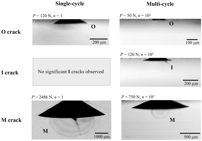
Examples of near-contact induced occlusal surface fracture morphologies in thick (d ≈ 6 mm) monolith glass bars (not subject to significant flexure upon loading), showing differences in critical loads for the onset of various damage modes for single-cycle and cyclic loading. Note: O, outer cone cracks; I, inner cone cracks; M, median cracks.
B. Design maps
Near-contact stress induced occlusal outer cone, inner cone, and median cracks are active in brittle plates on compliant supports. Since all-ceramic crowns typically have thicknesses d = 1.0 mm to 2.5 mm, occlusal surface cracks all have potential to cause through-thickness fracture and to compete with internal surface radial fracture (Fig. 5). In our experiments, we etched the internal surface of the glass plates with 9.5% hydrofluoric acid for 5 min to remove surface-handling flaws and thus to avoid radial cracking. The top, occlusal surface of the glass plates was lightly abraded with 600 grit SiC particles to introduce a scattered flaw population. The design map was constructed for the number of cycles n = nF required for any of these occlusal crack systems to reach the internal cementation surface of the glass plate under a given cyclic load Pm.36 Fig. 6a shows a thin glass layer (d = 1 mm) epoxy bonded to a polycarbonate support and subjected to cyclic loading in water. For Pm ≥ 200 N, outer cone cracks initiated at the first cycle and persistently propagated outward and downward. They remained dominant over other crack systems and penetrated through the entire glass layer, reaching the glass/polycarbonate interface. However, in the nominal biting force region (Pm ≈ 100 N), inner cone cracks, despite initiating well after their outer counterparts, became dominant and eventually penetrated through the glass layer. These inner cone cracks are potentially a dangerous source of through-thickness fracture, overlooked by routine in vitro single-cycle loading tests. No significant median fracture was observed in these thin layers (d = 1 mm). For thicker glass coatings (d = 2.2 mm) subject to cyclic loading, outer cone cracks dominated and were responsible for the through-thickness failure at high loads (Pm > 600 N), median cracks at mid-range loads (Pm = 300 N to 600 N), and inner cone fractures at low loads (Pm < 300 N) (Fig. 6b).
Figure 5.
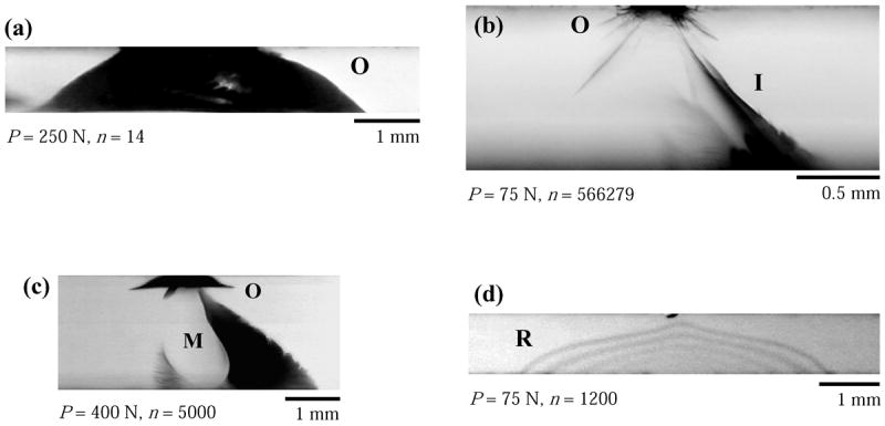
Examples of failure of brittle layers on compliant polycarbonate substrate by various damage modes: (a) O, outer cone crack, (b) I, inner cone crack, (c) M, median crack, and (d) R, radial crack. Note: photos are showing the glass coating layers only. The thicknesses of the glass layers are 1 mm for (a), (b), and (d) and 2.2 mm for (c). The top surface of the glass layers are abraded with 600 grit SiC to introduce a controlled flaw population, while the bottom surface of the glass coatings are etched with 9.5% hydrofluoric (HF) acid in (a), (b), and (c), and sandblasted with 50 μm alumina particles in (d) (mimicking the sandblast treatment in dentistry).
Figure 6.
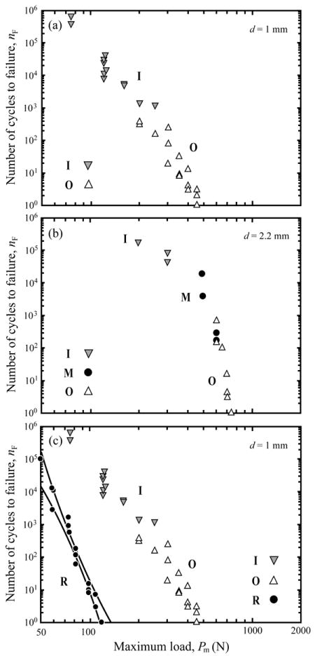
Number of cycles to failure nF as function of maximum contact load Pm for soda-lime glass/polycarbonate bilayers. Glass thickness (a) d = 1 mm, (b) d = 2.2 mm, and (c) d = 1 mm. In (a) and (b), the top, occlusal surface of glass layer is lightly abraded with 600 grit SiC particles, while the bottom, internal surface of glass is etched with HF. Note failure from different crack modes at different Pm. In (c), the top surface of glass is abraded, while the bottom surface is sandblasted with 50 μm alumina particles. Note the dominance of cementation internal surface radial (R) fracture in (c). Note: O, outer cone cracks; I, inner cone cracks; M, median cracks; R, radial cracks. Lines represent 95% confidence bounds to the radial crack initiation data.
If the internal surface of the glass plate is sandblasted with alumina particles (a technique commonly used to treat the ceramic internal surface for cement bond enhancement) and epoxy bonded to polycarbonate substrates and then loaded on the top surface with a tungsten carbide spherical indenter, the damaged internal surface becomes vulnerable to radial fracture. In Fig. 6c, we superimpose the radial fracture data on Fig. 6a, creating a complete design map for glass plates on polycarbonate bilayers. For 1 mm thick glass layer on soft polycarbonate, failure resulted exclusively from radial fracture, i.e. radial cracks formed before the outer or inner cone cracks intersected the coating/substrate interface. The two solid lines in Fig. 6c represent 95% confidence bounds to the radial crack initiation data. It is important to note that the formation of the internal surface radial cracks facilitates the flexure of the brittle layer, which in turn, alters its stress state. Therefore, the actual failure conditions for outer and inner cone cracks in Fig. 6c may differ from those in Fig. 6a. However, as discussed earlier, the failure condition for the radial fracture is defined as its initiation. The subsequent effect of radial cracks on the behavior of the outer and inner cone cracks is beyond the scope of this paper.
V. Discussion
We have investigated the fracture behavior of brittle layers on compliant substrates. The chief findings are: brittle materials are more vulnerable to cyclic fatigue; damage modes observed in single-cycle loading can form at much lower loads in cyclic loading. In addition, a new damage mode, deep penetrating inner cone cracks, can form from cyclic loading in water. Outer cone cracks form outside the contact area and their initiation and propagation rate are consistent with SCG determined by a classical crack velocity relation.34 Therefore it is possible to predict the onset and the subsequent penetration depth of outer cone cracks for cyclic loading at any given load/stress level and number of cycles, if the velocity exponent value of the brittle material is known. For reference, the velocity exponent N values for glass and a number of dental ceramics are summarized below: glass (N = 17), feldspathic porcelain (N = 17), lithium disilicate based glass-ceramic (Empress II, Ivoclar-Vivadent, Schaan, Liechtenstein) (N = 20), high purity zirconia (N = 25) and alumina (N = 26).3 The smaller N value, the material is more susceptible to stress corrosion driven SCG.
Inner cone cracks initiate from the surface fissures within the contact area and their crack propagation rates are determined by hydraulic pressure induced from entrapped water in addition to SCG.5,35 Median cracks inaugurate from the microscopic shear cracks or faults associated with a yield zone near the ceramic occlusal surface directly beneath the contact.21,37 Experimental observations showed that although inner cone and median cracks form much later than outer cone cracks, they propagate much faster.5,34 For the current flat specimens, the inner cone and/or median cracks appear to be relatively stable once they reach the ceramic cementation internal surface (rarely propagating along the ceramic/polymer interface). However, for actual 3-D dental crown morphology, the occlusal surface damage may result in chipping of the ceramic prostheses.38,39
Cementation internal surface radial cracks are induced by far-field flexural stress and have a strong SCG dependence. The critical load, PR, for radial crack initiation is determined predominately by the thickness and strength of the ceramic material (Appendix, Eq. 4). In addition, recent studies showed that seemingly innocuous surface damage (e.g. induced from materials processing and handling) at the ceramic internal surface can substantially reduce the critical loads for the onset of radial cracks due to damage accumulation under cyclic loading.40-43 Therefore, radial cracks are particularly dangerous for thin layers with abraded or damaged cementation internal surfaces. Radial cracks pop-in at a relative large scale (~5 mm to 10 mm laterally) which is on the same order of dimension for a posterior tooth or molar crown (~7 mm and 10 mm from buccal to palatal and mesial to distal respectively). In addition, when these large internal surface radial cracks form in a crown-like curved brittle layer on compliant substrate systems they can quickly extend to the margins, the base of the curved structure—a phenomenon that can not be simulated by the present flat brittle layer on compliant substrate approach.26,27,44 Therefore if radial cracks form in ceramic crowns, they can result in bulk fracture.
The critical load for radial crack initiation is also determined by the difference in elastic modulus between the crown and the cement/tooth dentin supporting structure (Appendix, Eq. 4).8,45 The effective modulus of cement/tooth dentin can be determined using a simple analytical relation developed by Lawn and colleagues (Appendix, Eq. 5).46 Monolithic (single layer) dental crowns are cemented (Ec = 2 GPa to 10 GPa) onto a tooth dentin support (Es = 16 GPa to 20 GPa). Analysis of critical loads for the onset of internal surface radial cracks enables evaluation of the critical loads for glass plates cemented (Ec ≈ 5 GPa, d ≈ 100 μm) to tooth dentin (Es ≈ 18 GPa) (Fig. 7). As can be seen, in thin brittle layers, radial cracks dominate for forces greater than 100 N (Fig. 7a). However, for forces at 75 N or smaller, inner cone cracks can compete with radial cracks, i.e. inner cone cracks can penetrate through the entire brittle layer before the formation of radial cracks (Fig. 7a). The dominance of radial fracture begins to lose its ground as the thickness of the brittle layer increases. Fig. 7b shows that for a thick glass layer d = 2.2 mm cemented onto a dentin-like support, fractures are exclusively from the occlusal surface damage: outer cone fracture at high loads (>600 N); median fracture at median to high loads (300 N to 600 N); and inner cone fracture at relatively low loads (<300 N). As can be seen, for persistent loading at nominal loads ~100 N, radial cracks are the most dangerous modes for the thin crowns (d < 1 mm), while inner cone cracks reach the ceramic cementation surface first for the thick crowns (d > 2 mm). However, the inner cone cracks, from the current observations, tend to arrest at the interface, leaving the cementation radial cracks the most dangerous mode.
Figure 7.
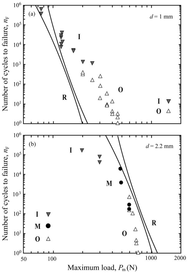
Projection of critical loads PR for the onset of cementation internal surface radial (R) cracks in soda-lime glass plates cemented to tooth dentin. Glass thickness (a) d = 1 mm and (b) d = 2.2 mm. The top surface of glass plates is lightly abraded with 600 grit SiC particles, whereas the bottom surface is sandblasted with 50 μm alumina particles. Note: O, outer cone cracks; I, inner cone cracks; M, median cracks; R, radial cracks. Lines represent 95% confidence bounds to the radial crack initiation data.
As discussed in a preceding paragraph, the effective modulus of luting cement and tooth dentin structure, which is determined by both elastic modulus and thickness of the luting cement (Appendix, Eqs. 5 and 6), is critical to initiate the cementation internal surface radial cracks. With knowledge of the bulk flexural strength value of ceramic coatings, Eqs. 4 - 6 (Appendix) can be used to predict the dependence of critical loads PR for internal surface radial cracking on cement moduli and thicknesses for any ceramic coating on a tooth dentin system under single-cycle loading. Fig. 8 shows an example of the critical load PR as a function of the cement modulus and thickness for a glass-ceramic (Empress, Ivoclar-Vivadent, Schaan, Liechtenstein) layer (d = 1.5 mm) cemented to tooth dentin system. As can be seen, when the cement layer is thin (h = 20 μm), critical loads for radial fracture are less sensitive to the cement modulus. However, the dependence of critical loads on the cement modulus becomes more pronounced as the cement thickness increases. Two distinctive regions of cement modulus can be identified. For cement modulus lower than dentin (Es ≈ 18 GPa), which represents most commercial luting cements (Ec = 2 GPa to 10 GPa), critical load drops as a cement layer thickness increases. The effect of cement thicknesses on critical loads becomes more significant for low modulus cements, such as Rely X ARC (Ec = 3.1 GPa), than high modulus ones, such as VarioLink II (Ec = 8.6 GPa). For cement modulus higher than dentin, e.g. a newly developed BisGMA–alumina composite cement (Ec ≈ 40 GPa) reported by Wang and co-workers,47 a thicker cement layer increases the critical load value. Therefore, utilizing cement with modulus greater than dentin can enhance the resistance to bulk radial fracture of ceramic crowns. Finally, the predicted critical load values for glass-ceramic crowns (Empress) cemented to dentin systems are based on single-cycle loading tests. Under cyclic fatigue loading, critical loads for internal cementation radial fracture can be reduced by a factor of two or more over several years.3 Ratcheting of stress from viscoplastic flow of the cement may further accelerate the degradation in critical loads of ceramics prostheses.48
Figure 8.
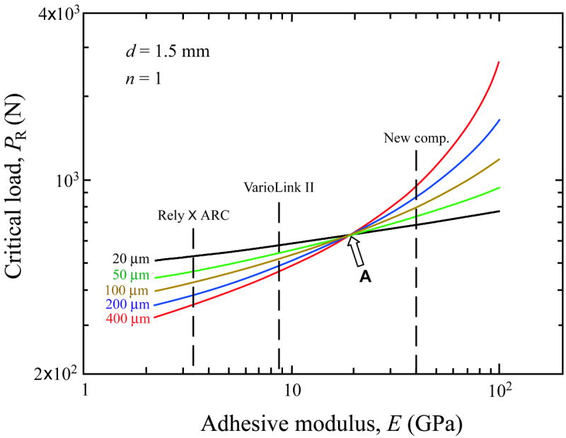
Prediction of the dependence of critical load PR on the cement modulus and thickness for a glass-ceramic (Empress I, Ivoclar-Vivadent, Schaan, Liechtenstein) layer (d = 1.5 mm) cemented to tooth dentin. Calculations are based on Eqs. 4 - 6 (Appendix), assuming the strength of Empress I is 160 MPa and the elastic modulus of tooth dentin is 18 GPa. Two distinctive regions separated by an arrow “A”, which represents the elastic modulus value of tooth dentin Es ≈ 18 GPa, of cement modulus can be identified.
In summary, the current investigation using a model glass on polycarbonate system revealed that damage can initiate at the occlusal and cementation internal surfaces of a ceramic prosthesis under mastication. While glass lacks of microstructural complexity compared to dental ceramics, our preliminary results find the same damage modes (outer cone, inner cone, median, and radial cracks) in Hertzian contact fatigue of glass-ceramic layers (Dicor, Empress I, and Empress II) cemented to dental composite (Z-100, 3M ESPE), porcelain veneered zirconia layers (LAVA, Procera Zirconia, and Vita In-Ceram YZ) cemented to dental composite (Z-100), porcelain veneered alumina layers (Procera Alumina) on dental composite (Z-100), and monolith Y-TZP layers (LAVA) on dental composite (Z-100). Our findings strongly suggest that single-cycle in vitro tests are inadequate to accurately simulate the cyclic masticatory function, since fatigue loading accelerates all damage and a new damage mode, inner cone fracture, can occur. Cementation internal surface radial cracks commonly occur in the thin layers (d < 1 mm), whereas occlusal surface fractures dominate in the thick layers (d > 2 mm). The occlusal surface cracking often results in chipping of the ceramic prosthesis, whereas the cementation internal surface radial cracks can lead to bulk fracture. Sandblast treatment of the ceramic internal surface increases the risk of bulk fracture of all-ceramic restoratives, including veneered zirconia systems.41,42 High modulus cement reduces the risk of bulk fracture in these prostheses.
Acknowledgments
Valuable discussions with Dr. Brian R. Lawn are appreciated. This investigation was sponsored by funding from the United States National Institute of Dental and Craniofacial Research 1R01 DE017925 (PI. Zhang) and P01 DE10976 (PI. Rekow) and the New York University Challenge Grant. Certain equipment, instruments or materials are identified in this paper in order to specify experimental details, and does not imply recommendation by the National Institute of Standards and Technology.
Appendix: Damage from Near-Contact and Far-Field Stresses
Consider a ceramic layer of thickness d cemented to a compliant substrate of modulus Es loaded on top surface with a hard sphere of radius r (Fig. 2a). The critical loads for the near-contact occlusal surface outer cone cracking (PC) and quasiplastic yield (PY) are given by:8
| (1) |
| (2) |
where KIC toughness and H hardness and E elastic modulus of the ceramic, A (= 8.63 × 10³) and D (= 0.848) dimensionless coefficients.20
The competition between outer cone fracture and quasiplastic yield in the Hertzian field is governed by:
| (3) |
The critical load for the far-field cementation internal surface radial crack (PR) is given by:46
| (4) |
where σ is the bulk flexural strength of the ceramic, and B (= 1.35) and C (~ 1) the dimensionless constants.49 E* is the effective modulus of the cement/substrate composite:46
| (5) |
where Ec and Es are the modulus of cement and substrate respectively. L is an experimentally determined dimensionless function:46
| (6) |
where α = 1.18, β = 0.33, γ = 3.13. d and h are thicknesses of the ceramic coating and cement layer, respectively.
References
- 1.Kelly JR. Clinically Relevant Approach to Failure Testing of All-Ceramic Restorations. The Journal of Prosthetic Dentistry. 1999;81(6):652–61. doi: 10.1016/s0022-3913(99)70103-4. [DOI] [PubMed] [Google Scholar]
- 2.Kelly JR. Dental Ceramics: Current Thinking and Trends. Dent Clin N Am. 2004;48:513–30. doi: 10.1016/j.cden.2004.01.003. [DOI] [PubMed] [Google Scholar]
- 3.Zhang Y, Lawn B. Long-term strength of ceramics for biomedical applications. Journal of Biomedical Materials Research Part B-Applied Biomaterials. 2004;69B(2):166–172. doi: 10.1002/jbm.b.20039. [DOI] [PubMed] [Google Scholar]
- 4.Kim DK, Jung Y-G, Peterson IM, Lawn BR. Cyclic Fatigue of Intrinsically Brittle Ceramics in Contact With Spheres. Acta Materialia. 1999;47(18):4711–25. [Google Scholar]
- 5.Zhang Y, Song J-K, Lawn BR. Deep Penetrating Conical Cracks in Brittle Layers from Hydraulic Cyclic Contact. Journal of Biomedical materials research. 2005;73B:186–93. doi: 10.1002/jbm.b.30195. [DOI] [PubMed] [Google Scholar]
- 6.Goodacre CJ, Bernal G, Rungcharassaeng K, Kan JY. Clinical complications in fixed prosthodontics. J Prosthet Dent. 2003;90(1):31–41. doi: 10.1016/s0022-3913(03)00214-2. [DOI] [PubMed] [Google Scholar]
- 7.Kelly JR. Ceramics in Restorative and Prosthetic Dentistry. Annual Reviews of Materials Science. 1997;27:443–68. [Google Scholar]
- 8.Lawn BR, Deng Y, Miranda P, Pajares A, Chai H, Kim DK. Overview: Damage in Brittle Layer Structures From Concentrated Loads. Journal of Materials Research. 2002;17(12):3019–36. [Google Scholar]
- 9.Diao DF, Kato K, Hollirigawa K. Fracture Mechanisms of Ceramic Coatings in Indentation. J Tribology- Transactions of the ASME. 1994;116(4):860–9. [Google Scholar]
- 10.Dong XD, Darvell BW. Stress Distribution and Failure Mode of Dental Ceramic Structures under Hertzian Indentation. Dent Mater. 2003;19:542–51. doi: 10.1016/s0109-5641(02)00103-3. [DOI] [PubMed] [Google Scholar]
- 11.Hojjatie B, Anusavice KJ. Three-Dimensional Finite Element Analysis of Glass-Ceramic Crown. J Biomech. 1990;23(11):1157–66. doi: 10.1016/0021-9290(90)90008-q. [DOI] [PubMed] [Google Scholar]
- 12.Pallis K, Griggs J, Woody RD, Guillen GE, Miller AW. Fracture Resistance of Three All-Ceramic Restorative Systems for Posterior Applications. J Prosthet Dent. 2004;91:561–9. doi: 10.1016/j.prosdent.2004.03.001. [DOI] [PubMed] [Google Scholar]
- 13.Shrotriya P, Wang R, Katsube N, Seghi R, Soboyejo WO. Contact damage in model dental multilayers: an investigation of the influence of indenter size. J Mater Sci Mater Med. 2003;14(1):17–26. doi: 10.1023/a:1021541101823. [DOI] [PubMed] [Google Scholar]
- 14.Tsai YL, Petsche PE, Anusavice KJ, Yang MC. Influence of Glass-Ceramic Thickness on Hertzian and Bulk Fracture Mechanisms. Int J Prosthodont. 1998;11(1):27–32. [PubMed] [Google Scholar]
- 15.Lawn BR, Wilshaw TR. Indentation Fracture: Principles and Applications. Journal of Materials Science. 1975;10(6):1049–81. [Google Scholar]
- 16.Mikosza AG, Lawn BR. Section-and-Etch Study of Hertzian Fracture Mechanics. Journal of Applied Physics. 1971;42(13):5540–45. [Google Scholar]
- 17.Wilshaw TR. The Hertzian Fracture Test. Journal of Physics D: Applied Physics. 1971;4(10):1567–81. [Google Scholar]
- 18.Gurney C, Hunt J. Quasi-Static Crack Propagation. Proceedings of the Royal Society of London. 1967;A299:508. [Google Scholar]
- 19.Lee KS, Jung Y-G, Peterson IM, Lawn BR, Kim DK, Lee SK. Model for Cyclic Fatigue of Quasiplastic Ceramics in Contact With Spheres. Journal of the American Ceramic Society. 2000;83(9):2255–62. [Google Scholar]
- 20.Rhee Y-W, Kim H-W, Deng Y, Lawn BR. Brittle Fracture Versus Quasiplasticity In Ceramics: A Simple Predictive Index. Journal of the American Ceramic Society. 2001;84(3):561–65. [Google Scholar]
- 21.Lawn BR, Padture NP, Cai H, Guiberteau F. Making Ceramics ‘Ductile’. Science. 1994;263:1114–16. doi: 10.1126/science.263.5150.1114. [DOI] [PubMed] [Google Scholar]
- 22.Fischer-Cripps AC, Lawn BR. Stress Analysis of Contact Deformation in Quasi-Plastic Ceramics. Journal of the American Ceramic Society. 1996;79(10):2609–18. [Google Scholar]
- 23.Fischer-Cripps AC, Lawn BR. Indentation Stress–Strain Curves for “Quasi-Ductile” Ceramics. Acta Materialia. 1996;44(2):519–27. [Google Scholar]
- 24.Lawn BR. Indentation of Ceramics With Spheres: A Century After Hertz. Journal of the American Ceramic Society. 1998;81(8):1977–94. [Google Scholar]
- 25.Lawn BR, Padture NP, Guiberteau F, Cai H. A Model for Microcrack Initiation and Propagation Beneath Hertzian Contacts in Polycrystalline Ceramics. Acta Metallurgica. 1994;42(5):1683–93. [Google Scholar]
- 26.Kim JW, Bhowmick S, Chai H, Lawn BR. Role of substrate material in failure of crown-like layer structures. J Biomed Mater Res B Appl Biomater. 2007;81(2):305–11. doi: 10.1002/jbm.b.30666. [DOI] [PubMed] [Google Scholar]
- 27.Qasim T, Bush MB, Hu X, Lawn BR. Contact Damage in Brittle Coating Layers: Influence of Surface Curvature. Journal of Biomedical Materials Research. 2005;73B:179–185. doi: 10.1002/jbm.b.30188. [DOI] [PubMed] [Google Scholar]
- 28.Kelly JR, Giordano R, Pober R, Cima MJ. Fracture Surface Analysis of Dental Ceramics: Clinically Failed Restorations. International Journal of Prosthodontics. 1990;3:430–40. [PubMed] [Google Scholar]
- 29.Deng Y, Lawn BR, Lloyd IK. Characterization of damage modes in dental ceramic bilayer structures. J Biomed Mater Res. 2002;63B:137–45. doi: 10.1002/jbm.10091. [DOI] [PubMed] [Google Scholar]
- 30.Chai H, Lawn BR, Wuttiphan S. Fracture Modes In Brittle Coatings With Large Interlayer Modulus Mismatch. Journal of Materials Research. 1999;14(9):3805–17. [Google Scholar]
- 31.Lawn BR, Deng Y, Thompson VP. Use of Contact Testing in the Characterization and Design of All-Ceramic Crownlike Layer Structures: A Review. The Journal of Prosthetic Dentistry. 2001;86(5):495–510. doi: 10.1067/mpr.2001.119581. [DOI] [PubMed] [Google Scholar]
- 32.Jung Y-G, Pajares A, Banerjee R, Lawn BR. Strength of Silicon, Sapphire and Glass in the Subthreshold Flaw Region. Acta Materialia. 2004;52:3459–3466. [Google Scholar]
- 33.Johnson KL, O’Connor JJ, Woodward AC. The Effect of Indenter Elasticity on the Hertzian Fracture of Brittle Materials. Proc R Soc London Ser A. 1973;334:95. [Google Scholar]
- 34.Zhang Y, Bhowmick S, Lawn BR. Competing Fracture Modes in Brittle Materials Subject to Concentrated Cyclic Loading in Liquid Environments: Monoliths. Journal of Materials Research. 2005;20(8):2021–9. [Google Scholar]
- 35.Chai H, Lawn BR. Hydraulically Pumped Cone Fracture in Brittle Solids. Acta Materialia. 2005;53:4237–4244. [Google Scholar]
- 36.Bhowmick S, Zhang Y, Lawn BR. Competing fracture modes in brittle materials subject to concentrated cyclic loading in liquid environments: Bilayer structures. Journal of Materials Research. 2005;20(10):2792–2800. [Google Scholar]
- 37.Peterson IM, Pajares A, Lawn BR, Thompson VP, Rekow ED. Mechanical Characterization of Dental Ceramics Using Hertzian Contacts. Journal of Dental Research. 1998;77(4):589–602. doi: 10.1177/00220345980770041201. [DOI] [PubMed] [Google Scholar]
- 38.Pjetursson BE, Sailer I, Zwahlen M, Hämmerle CHF. A Systematic Review of the Survival and Complication Rates of All-Ceramic and Metal-Ceramic Reconstructions after an Observation Period of at Least 3 Years. Part I: Single Crowns. Clin Oral Impl Res. 2007;18(3):73–85. doi: 10.1111/j.1600-0501.2007.01467.x. [DOI] [PubMed] [Google Scholar]
- 39.Sailer I, Pjetursson BE, Zwahlen M, Hämmerle CHF. A Systematic Review of the Survival and Complication Rates of All-Ceramic and Metal-Ceramic Reconstructions after an Observation Period of at Least 3 Years. Part II: Fixed Dental Prostheses. Clin Oral Impl Res. 2007;18(3):86–96. doi: 10.1111/j.1600-0501.2007.01468.x. [DOI] [PubMed] [Google Scholar]
- 40.Zhang Y, Lawn BR. Fatigue Sensitivity of Y-TZP to Microscale Sharp-Contact Flaws. Journal of Biomedical materials research. 2005;72B:388–92. doi: 10.1002/jbm.b.30174. [DOI] [PubMed] [Google Scholar]
- 41.Zhang Y, Lawn BR, Malament KA, Thompson VP, Rekow ED. Damage Accumulation and Fatigue Life of Sandblasted Dental Ceramics. The International Journal of Prosthodontics. 2006;19(5):442–448. [PubMed] [Google Scholar]
- 42.Zhang Y, Lawn BR, Rekow ED, Thompson VP. Effect of Sandblasting on the Long-Term Performance of Dental Crowns. Journal of Biomedical materials research. 2004;71B(2):381–6. doi: 10.1002/jbm.b.30097. [DOI] [PubMed] [Google Scholar]
- 43.Zhang Y, Pajares A, Lawn B. Fatigue and Damage Tolerance of Y-TZP Ceramics in Layered Biomechanical Systems. Journal of Biomedical Materials Research. 2004;71B(1):166–71. doi: 10.1002/jbm.b.30083. [DOI] [PubMed] [Google Scholar]
- 44.Qasim T, Ford C, Bush MB, Hu X, Lawn BR. Effect of off-axis Concentrated Loading on Failure of Curved Brittle Layer Structures. Journal of Biomedical Materials Research. 2006;76(B)(2):334–339. doi: 10.1002/jbm.b.30373. [DOI] [PubMed] [Google Scholar]
- 45.Lawn BR. Ceramic-based Layer Structures For Biomechanical Applications. Current Opinion in Solid State and Materials Science. 2002;6(3):229–35. [Google Scholar]
- 46.Kim JH, Miranda P, Kim DK, Lawn BR. Effect of an Adhesive Interlayer on the Fracture of a Brittle Coating on a Supporting Substrate. Journal of Materials Research. 2003;18(1):222–27. [Google Scholar]
- 47.Wang Y, Lee JJ, Lloyd IK, Wilson OC, Jr, Rosenblum M, Thompson V. High modulus nanopowder reinforced dimethacrylate matrix composites for dental cement applications. J Biomed Mater Res A. 2007 doi: 10.1002/jbm.a.31029. In press. [DOI] [PubMed] [Google Scholar]
- 48.Huang M, Niu X, Soboyejo WO. Creep induced rate effects on radial cracks in multilayered structures. J Mater Sci Mater Med. 2007;18(1):65–9. doi: 10.1007/s10856-006-0663-z. [DOI] [PubMed] [Google Scholar]
- 49.Miranda P, Pajares A, Guiberteau F, Deng Y, Lawn BR. Designing Damage-Resistant Brittle-Coating Structures: I. Bilayers. Acta Materialia. 2003;51(14):4347–56. [Google Scholar]
- 50.Lawn BR, Pajares A, Zhang Y, Deng Y, Polack M, Lloyd I, Rekow ED, Thompson VP. Materials Design in the Performance of All-Ceramic Crowns. Biomaterials. 2004;25(14):2885–92. doi: 10.1016/j.biomaterials.2003.09.050. [DOI] [PubMed] [Google Scholar]


