Abstract
Hierarchical heterostructures of beta-iron oxyhydroxide (β-FeOOH) nanostructures on electrospun TiO2 nanofibers were synthesized by a facile hydrothermal method. This synthesis method proves to be versatile to tailoring of β-FeOOH structural design that cuts across zero-dimensional particles (TF-P), one-dimensional needles (TF-N) to two-dimensional flakes (TF-F). In addition, synthesizing such oxyhyroxide nanostructures presents the advantage of exhibiting similar functional performances to its oxides counterpart however, without the need to undergo any annealing step which leads to undesirable structural collapse or sintering. The as-prepared hierarchical heterostructures possess high surface area for dye adsorptivity, efficient charge separation and visible photocatalytic activity. Also, for the first time, hydrogen gas sensing has been demonstrated on β-FeOOH nanostructures at room temperature. The reported hierarchical heterostructures of β-FeOOH on TiO2 nanofibers afford multiple functions of photocatalysis and sensing which are highly promising for environment monitoring and clean up applications.
Among various semiconductors, titanium (IV) dioxide (TiO2) has been known as an excellent material for photocatalytic purposes due to its unique characteristics in band position, surface structure, as well as its chemical stability and non-toxicity1,2,3,4. There are several ways to synthesize TiO2 and one of it is by electrospinning. Electrospinning is a simple and versatile technique that is capable of producing nanofibers with diameters ranging from 50 to 500 nm5. This preparation method has the advantages of easy deposition and versatility in the synthesis of polymers, composites and ceramics. Due to their nanosize, nanofibers possess a range of attractive properties such as high surface area to volume ratio, flexibility of structures and mechanical integrity6. The formation of nanofibers with TiO2 allows a combination of their elevated surface area and the intrinsic properties of TiO2, thereby opening an enormous potential in this material for applications in environmental remediation and protection, photocatalysis, dye-sensitized solar cells, gas sensors, and batteries7,8,9,10,11.
However, TiO2 is only able to utilize the photons in the UV region (λ < 380 nm) due to its large band gap (Eg = 3.2 eV), severely limiting its practical applications in sun light and indoor environment12,13,14. A possible strategy to overcome this drawback is to couple TiO2 with narrow bandgap semiconductors capable of harvesting the photons in the visible range15,16,17. Fe2O3 is considered to be a suitable semiconductor to be coupled with TiO2 due to its high photocatalytic activity and approximate band gap energy as compared with TiO218,19,20,21. Fe2O3 can be prepared by the forced hydrolysis of Fe(III) solutions where iron oxyhydroxides (α-FeOOH and β-FeOOH) are intermediate products, and transform to Fe2O3 through post treatment22,23,24,25.
The intermediate product β-FeOOH (Eg = 2.12 eV)26 is actually capable of showing photocatalytic activity in the visible range. β-FeOOH has a channel structure parallel to the c-axis and this tunnel structure makes β-FeOOH an especially interesting material which is promising as a photo-Fenton catalyst in the heterogeneous system27,28,29. β-FeOOH is an ideal material to couple with the TiO2 nanofibers for photocatalytic activity in the visible range because it exhibits the same performance as Fe2O3 but has a simpler synthesis process where unlike Fe2O3, it does not have to undergo the annealing process which may lead to the collapse of hierarchical structures. Moreover, a variety of morphologies can be easily obtained without the use of surfactant. However, there are very few reports of β-FeOOH-TiO2 hierarchical nanostructures. Hierarchical and branched nanostructures possess the combined advantages of rapid charge transfer pathway for carrier collection, large surface area for increased reaction sites, and excellent light trapping30,31,32 which are all favorable characteristics for photocatalytic reactions. The large surface area of the structure also makes it highly suitable for gas sensing applications.
In this work, we have synthesized β-FeOOH on TiO2 nanofibers and 3 different types of nanostructures were easily obtained by adjusting the concentration of the FeCl3 aqueous solution without using any surfactants. TiO2@FeOOH in the forms of flakes (TF-F), particles (TF-P) and needles (TF-N) were prepared with [FeCl3] = 0.02, 0.05 and 0.1 M, respectively. The as-obtained products are unique in structure and porous in texture, and are evaluated for their methyl orange (MO) dye degradation and hydrogen (H2) gas sensing performances. The samples displayed enhanced photodegradation capabilities and gas sensing at room temperature. The TiO2@FeOOH composites also proved to be active in visible light and were able to degrade MO under visible light illumination.
Results and Discussion
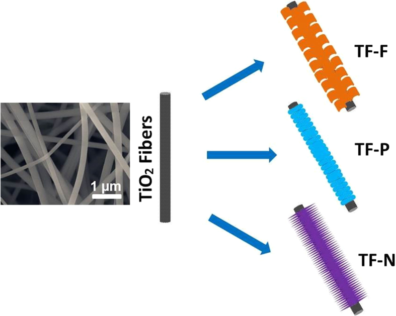
The synthesis of FeOOH architecture onto the TiO2 nanofibers is illustrated in Fig. 1. The electrospun TiO2 nanofibers with an average diameter of 200 nm served as hard template for the growth of different FeOOH hierarchical structures. By controlling the concentrations of FeCl3 solution, FeOOH with different architectures can be fabricated through a facile hydrothermal process without introducing any surfactants. TiO2@FeOOH in the forms of flakes, particles and needles were obtained with [FeCl3] = 0.02, 0.05 and 0.1 M, respectively. The as-obtained products have shown to be unique in structure and porous in texture, and are evaluated for their dye degradation and H2 gas sensing performances.
Figure 1. FESEM image of TiO2 fiber and the formation scheme of the Samples TF-F, TF-P, and TF-N.
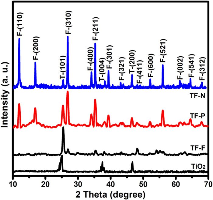
The pristine TiO2 nanofibers are shown in the SEM image in Fig. 1, where a diameter of ca. 200 nm and smooth surface can be clearly observed. After the growth of FeOOH architectures, the morphologies of TiO2@FeOOH are as shown in Fig. 2. With the lowest concentration of FeCl3 in this work, ultrafine nanoflakes were formed on the TiO2 fibers, thickening the fiber diameters up to 500 nm (Fig. 2a,b). When [FeCl3] was increased to 0.05 M, the flake-like structure disappeared and changed to nanoparticles. The diameter of the fibers was increased from 200 nm to 300 nm, indicating a thickness of 50 nm of the particle-like FeOOH layer (Fig. 2c,d). The further increase of FeCl3 to 0.1 M leads the particles to grow longer into needles, which are revealed by SEM results in Fig. 2e,f. The diameters of the cables are measured to reach 500 nm again, which marked the length of the needles at ~60 nm. However, it is interesting to find some cross-shaped particles appearing amongst the sample (marked in yellow circle), which may be due to over-crystallization caused by the higher concentration of Fe3+. The crystallographic phases of all the as-obtained TiO2@FeOOH samples together with the pure TiO2 (as a comparison) were examined by XRD (Fig. 3). All the indexed peaks marked with F can be assigned to β-FeOOH (JCPDS 75-1549)33, while the peaks marked with T can be attributed to anatase TiO2 (JCPDS 21-1272)34. No peaks from other impurities can be detected which shows the successful deposition of FeOOH on the TiO2 fibers.
Figure 2. FESEM images of Samples TF-F (a and b), TF-P (c and d), and TF-N (e and f).
Figure 3. XRD patterns of the Samples TF-F, TF-P, and TF-N.
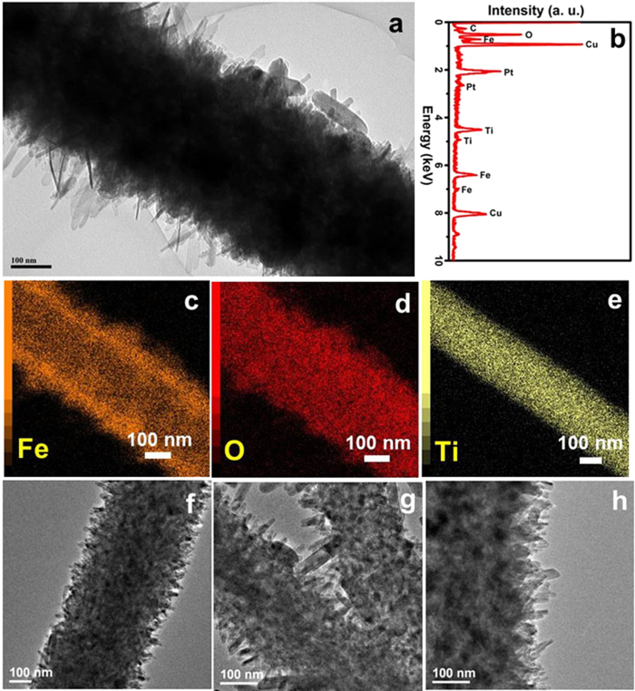
The detailed morphologies and compositions of the as-fabricated TiO2@FeOOH nanocables are further examined by TEM and elemental mapping. Figure 4a shows a TEM image of the Sample TF-F, where ultrafine nanoflakes growing from the fiber can be observed. The diameter of the nanocable is estimated to be around 500 nm, which is consistent with the previous SEM findings. The chemical composition of the TF-F is revealed by the EDX result shown in Fig. 4b, where the presence of Fe, Ti, O and C is confirmed (the peaks of Cu and Pt are attributed to the Cu substrate and Pt sputtering for SEM characterization respectively). In order to further analyze the typical core-shell structure of the TF-F nanocables, elemental mapping was also performed. The mappings of Fe, O and Ti are presented in Fig. 4c to e, clearly demonstrating the core-shell structure of the cables, where TiO2 fiber is encapsulated by the FeOOH architecture. Furthermore, no Ti is detected in the shell structure which shows that Ti has been confined within the cable cores, ensuring the mechanical stability of the entire structure. As a comparison, the TEM results of Sample TF-P and TF-N are also presented in Fig. 4 to show the differences of all the three samples. The TF-P sample is shown as Fig. 4f, in which tiny particles can be observed along the cable structure, compared to the much longer needle-like structure for sample TF-N (Fig. 4g,f).
Figure 4. TEM (a, f, g and h), EDX (b) and elemental mappings (c, d and e) of the Sample TF-F (a-e), TF-P (f) and TF-N (g and h).
The BET measurements were performed at 77 K to investigate the textural characteristics of all the three samples. N2 adsorption-desorption isotherms of all the samples are shown in Fig. 5 with insets illustrating their corresponding pore size distributions obtained from respective desorption branches. These isotherms can be categorized as type IV with small hysteresis loops observed at a relative pressure of 0.4-0.9 for all the three samples. The BET specific surface areas are calculated to be 67, 21 and 64 m2 g−1 for samples TF-F, TF-P and TF-N, respectively, showing the porous texture of all the samples. It can be concluded from the pore size distributions that TF-P and TF-N have pores with diameters of ~3.4 and 3.2 nm, respectively, while TF-F possesses a larger pore size at ~4.4 nm. In virtue of the porous texture and high surface area, the as-obtained TiO2@FeOOH core-shell nanocables would provide more active sites for photocatalytic reactions and gas absorption compared to common materials.
Figure 5. BET results of the Sample TF-F (a), TF-P (b), and TF-N (c).
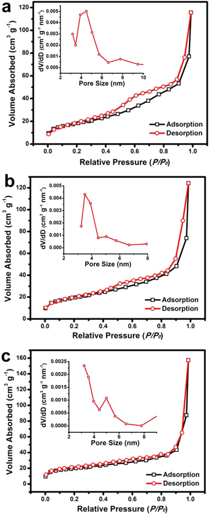
The insets show the corresponding pore size distributions obtained from desorption isotherms.
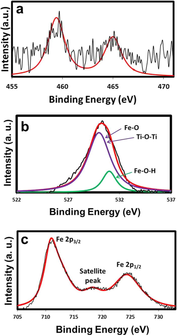
The elemental composition of the TiO2@FeOOH nanocables is shown by the XPS spectra in Fig. 6. The peaks of Ti 2p3/2 at 459.4 eV and Ti 2p1/2 at 465.0 eV indicate the presence of Ti4+ and that Ti is present in the form of TiO235. The O1s peak can be deconvoluted into 2 peaks located at 530 and 531 eV. The peak at 531 eV corresponds to the Fe-O-H bond36 while the peak at 530 eV can be attributed to both the Fe-O36 and Ti-O-Ti bonds37. The presence of Fe-O and Fe-O-H bonds suggest the formation of FeOOH while the Ti-O-Ti bond indicates the presence of TiO2. The formation of FeOOH is also proven by the Fe 2p3/2 and Fe 2p1/2 peaks at 711 and 724.4 eV respectively which corresponds to Fe3+ 38. The Fe 2p3/2 satellite peak at 719 eV is a characteristic peak of Fe3+, similar to other iron oxide samples of only Fe3+ states36. The XPS results of the typical TF-F sample after UV-vis photocatalysis is also provided as Figure S1 (see in the Supplementary Information), where no peak shifts can be observed compared to that before photocatalytic reaction.
Figure 6. XPS results of the typical TF-F sample.
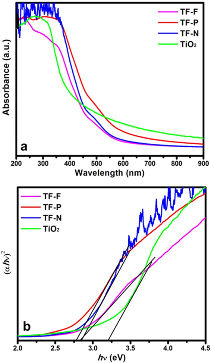
The UV-vis absorbance spectra of the TiO2@FeOOH nanocables are shown in Fig. 7a. The TiO2 nanofibers display photoabsorption in the UV region with an absorption edge at about 380 nm, but this absorption edge shifted to higher wavelengths with the addition of FeOOH. From the extrapolation of the straight line region of the Tauc plots in Fig. 7b, the bandgap is estimated to be 3.2 eV for TiO2 nanofibers. The bandgaps of the TiO2@FeOOH nanocables are narrower at 2.75, 2.8 and 2.81 eV for the TF-P, TF-F and TF-N respectively. The narrowing of bandgap is due to the coupling of TiO2 with β-FeOOH. The formation of Fe-O-Ti bonds will overlap the conduction band of TiO2 and d-orbital of Fe3+ 39, allowing the composite to harness visible light for photocatalytic reactions.
Figure 7. (a) UV-vis absorbance spectra and Tauc plot of the TF samples.
The most commonly used photocatalyst for dye degradation is TiO2 due to its low cost, high catalytic activity and long-term stability40. Han et al. reported the synthesis of TiO2 nanosheets with (001) facets for photocatalytic MO degradation under UV light, and the photocatalytic results have shown the superiority of their TiO2 nanosheets over the commercial P2541. A later work by Sun et al. has developed a TiO2-Graphene composite for improved UV-light photocatalytic activity. In their experiments, the dye degradation property of P25, TiO2 nanotubes, TiO2 nanosheets are also compared to show the enhanced performance of the as-prepared TiO2-Graphene composite42. In addition, the morphological investigation is also performed to study the relationship between the photocatalytic property and material structures. A recent work by Fu et al. has demonstrated the synthesis of TiO2 with different shapes with different performances in photocatalytic MO degradation43. Unfortunately, TiO2 is a wide-bandgap semiconductor, which is active under UV light only, limiting its harvesting capability for solar energy. Also, hydrofluoric acid (HF, extremely corrosive) is employed in some of the method for TiO2 synthesis, making those methods not so practical41,43. However, TiO2@FeOOH for visible-light photocatalysis is rarely reported. In our work, TiO2 nanofibers are obtained by an electrospin method, involving no toxic or corrosive chemicals. Furthermore, β-FeOOH materials with different nanostructures are grown onto the TiO2 nanofibers to form the TiO2-FeOOH hybrids, which are proven to be sensitive to the visible light irradiation. Hence, the as-fabricated TiO2 supported β-FeOOH is able to degrade the MO under the whole spectrum of sun light, which could be a more efficient photocatalyst.
The photocatalytic degradation of MO was used to demonstrate the enhanced photocatalytic activity of the TiO2@FeOOH nanocables. The degradation kinetics of MO was measured via the changes in their concentration, which was calculated from the absorbance peaks. Figure 8a shows the time profiles of the decrease in MO concentrations in the presence of TiO2@FeOOH nanocables under UV-Vis illumination. A blank experiment was carried out to show that photodegradation is not apparent in the absence of photocatalyst and H2O2. When H2O2 was added, photodegradation of MO was relatively slow and the reaction was completed only after 120 min of irradiation. With the addition of TiO2 nanofibers and H2O2, the MO could be fully degraded within 100 min. Comparatively, the TiO2@FeOOH nanocables showed enhanced photocatalytic activity under UV-Vis irradiation and were able to fully degrade the MO dye after 40-80 min, albeit at varying rates. The photodegradation activity was further analyzed by studying the pseudo-first order kinetics of the various photocatalysts as shown in Fig. 8b. This quantitative analysis is derived using the pseudo-first order model44 as follows:
 |
where C0 and Ct are the concentrations of MO at time 0 and t respectively, and k is the pseudo-first order rate constant.
Figure 8. (a) Degradation kinetics and (b) pseudo-first order kinetics of time evolution MO photodegradation study in the presence of TF samples under UV-visible illumination.
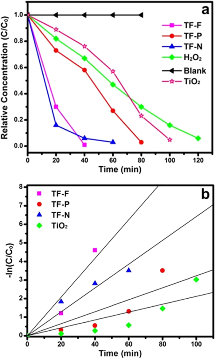
The pseudo-first order rate constants, k, of the plain TiO2 nanofibers and TiO2@FeOOH nanocables are summarised in Table 1. The constant k of TF-F is the highest at 0.1041 min−1 while that of TF is the lowest at 0.0212 min−1. The enhancement in photodegradation exhibited by the TiO2@FeOOH nanocables can be attributed to the heterogeneous photo-Fenton-like process, where large amounts of free hydroxyl radicals are rapidly generated from the reaction between FeOOH and H2O2 under UV-Vis irradiation45. Peroxide complex species are initially formed at Fe3+ active sites on the surface of the catalyst. The iron complex then undergoes a cleavage by UV-Vis irradiation to form Fe2+ complex. The unstable Fe2+ complex is rapidly oxidized by H2O2 to form hydroxyl radicals which could degrade MO38. Furthermore, under UV-Vis irradiation, electron-hole pairs are generated on the TiO2@FeOOH surface. The excited electrons will transfer from the conduction band of FeOOH to that of TiO2. This in turn results in reduced recombination, and the long-lived charge separated states promote generation of photoreactive oxidative species, i.e.·O2− and OH·46,47, which are responsible for degrading MO. OH· radicals are also formed from the reduction of H2O2 by the trapped electrons and via self-decomposition by UV-Vis illumination, as shown below48,49:
 |
 |
Table 1. Pseudo-first order kinetics of time evolution MO photodegradation under UV-visible illumination.
| Photocatalysts | Kinetic constants, k (min−1) | Correlation coefficient, R2 |
|---|---|---|
| TF-F | 0.1041 | 0.9154 |
| TF-P | 0.0323 | 0.7596 |
| TF-N | 0.0642 | 0.9309 |
| TF | 0.0212 | 0.7335 |
The degradation results clearly show that TF-F has the best photocatalytic performance amongst the TiO2@FeOOH nanocables. This is most likely attributed to the high surface area of TF-F (67 m2/g) as compared to TF-N (64 m2/g) and TF-P (21 m2/g). With a larger surface area, TF-F has more sites for the photocatalytic degradation of MO compared to the other composites. Moreover, the FeOOH flakes have a 2D structure while FeOOH needles are 1D and FeOOH particles are 0D. 2D structures generally have better charge transport properties than 1D and 0D structures50, thus the chances of recombination and trapping during the transport of photoexcited electrons from the conduction band of FeOOH to that of TiO2 is also reduced. As a result, more photoreactive oxidative species are produced, leading to enhanced MO photodegradation rate. To investigate the stability of the TF samples, the TF-N sample was re-collected and characterized by XRD. The peak-match results have shown that there is no phase change after irradiation for up to 3 h, indicating the stability of the materials (Figure S2).
The degradation kinetics of all the three TF samples without the addition of H2O2 are also carried out and the results are shown in Figure S3, from which degradation processes are observed to be much slower and less efficient compared to the cases with H2O2 present.
Besides photodegradation of MO under UV-Vis illumination, the TiO2@FeOOH nanocables are also capable of degrading MO under visible illumination (Fig. 9a). Contrary to that of UV-Vis illumination, no significant degradation of MO was observed when only H2O2 was added to MO. This is because self-decomposition of H2O2 does not occur under visible illumination, and hence, no OH· radicals were formed to degrade MO. When TiO2 nanofibers were added, the MO was degraded after 180 min of visible illumination. The photocatalytic activity in visible illumination can probably be attributed to photoreaction of the peroxide complex that is formed on the TiO2 surface. During this process, an electron is transferred from the photoexcited complex to the conduction band of TiO2, and then transferred to H2O2, leading to the generation of an OH− ion and an OH· radical which can degrade MO51. The degradation was even faster when TiO2@FeOOH nanocables were used, where TF-F degraded the MO in 80 min with a constant k of 0.0381 min−1 as shown in Fig. 9b and Table 2. The increase in degradation time of 40 to 60 min for all the samples can be attributed to the reduced amount of electron-hole pairs generated in visible light since electron-holes pairs could be generated from FeOOH and less effectively from TiO2. In order to study the adsorption property of the as-prepared TF samples, the adsorption kinetics for all the three TF samples without light irradiation are presented in Figure S4. A physical adsorption may have occurred for all the three samples in the first 60 minutes possibly due to the electrostatic force and high surface areas. Thereafter, some adsorbed MO molecules desorbed and re-enter into the solution with effect of the magnetic stirring (the C/C0 values recovered to 0.27, 0.56 and 0.42 for TF-F, P and N). This has shown a good adsorption property of our materials, which is advantageous to photocatalytic degradation. It also should be noted that the C/C0 values without light irradiation are still much higher than those in the presence of visible or UV light, which clearly show the photocatalytic activities of the as-prepared TF samples.
Figure 9. (a) Degradation kinetics and (b) pseudo-first order kinetics of time evolution MO photodegradation study in the presence of TF samples under visible illumination.
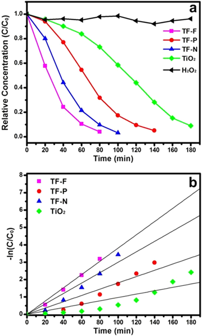
Table 2. Pseudo-first order kinetics of time evolution MO photodegradation under visible illumination.
| Photocatalysts | Kinetic constants, k (min−1) | Correlation coefficient, R2 |
|---|---|---|
| TF-F | 0.0381 | 0.988 |
| TF-P | 0.0181 | 0.9015 |
| TF-N | 0.03 | 0.9372 |
| TF | 0.0097 | 0.7871 |
In the gas sensing, hematite (Fe2O3) is extensively used by the research community because of the thermodynamic stability and abundant in earth52. Many efforts have been focused on the synthesis of nanostructured Fe2O3 with different shapes and morphologies. Wang et al. have reported Fe2O3 nanowires for gas sensing application and their obtained results have presented better performance of the Fe2O3 nanowires over the commercial Fe2O3 powder53. In another work by Hao et al., different hierarchical Fe2O3 architectures were prepared using various synthetic conditions. The gas sensing property of different Fe2O3 architectures were evaluated and compared54. In recent years, hematite based nanocomposites were developed to improve the gas sensing performance. For example, Ag-α-Fe2O3 composite material was reported by Liu et al. through a facile solution-based method. The Ag loaded hematite has shown the best performance when compared to the unloaded Fe2O3 and Fe2O3 nanocubes55. However, rare reports have been seen for the gas sensing using FeOOH as straightforward sensor materials. Herein we have grown the β-FeOOH onto the TiO2 nanofibers to create the TF hybrid materials with high specific surface areas. The as-derived TF materials have been used as gas sensor electrode directly without converting them to Fe2O3 by heat treatment, which may free the materials from morphological changes or structural collapse. In addition, the TF hybrid materials-based gas sensors are capable of functioning at room temperature and shows better sensing performance than some of the Fe2O3 gas sensors reported in literature56,57. The gas sensors reported by Flak et al.56 and Long et al.57 are operated at 300 °C and they show sensitivities of less than 8 in 500 ppm of H2.
The H2 sensing properties of TiO2@FeOOH nanocables at room temperature are also investigated. The samples are placed in a homemade gas sensing setup where the ambient in the sensing chamber is switched periodically between CDA and H2 gas of various concentrations (100 to 500 ppm). The resistance of the samples are observed to decrease in H2 ambient and increase in CDA ambient. The sensitivity of the sensor is calculated by
 |
where Ra is the resistance of the sample in CDA and Rg is the resistance of the sample in H2 gas. The TiO2@FeOOH nanocables were tested and their sensing responses to H2 gas are plotted in Fig. 10a. It is evident that the composites are all capable of sensing H2 gas at room temperature, with TF-F exhibiting the highest sensitivity of 52.5 in 500 ppm of H2 gas. TF-N has a sensitivity of 28.9 while TF-P showed a lower sensitivity of 12.7. TiO2 nanofibers have the lowest sensitivity of 4.
Figure 10. (a) Sensitivity of the prepared TF samples at 500 ppm of hydrogen.
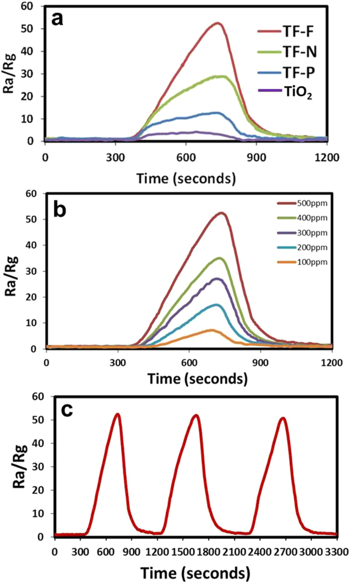
. (b) Sensitivity of the prepared TF-F sample as the gas ambient is switched from air to various concentrations (100–500 ppm) of hydrogen at room temperature. (c) Dynamic gas response (Ra/Rg ) of the prepared TF-F sample at 500 ppm.
The H2 gas sensing mechanism of the TiO2@FeOOH nanocables can be explained by the adsorption and desorption of O2 molecules at the surface of the TiO2@FeOOH nanocables. When the TiO2@FeOOH nanocables are exposed to CDA, the O2 molecules present in the air will adsorb onto the surface of the TiO2@FeOOH nanocables:
 |
The physisorbed O2 molecules will trap electrons from the conduction band of the TiO2@FeOOH nanocables to form chemisorbed O2 species of O−, O2− and O2−, with O2− being favorably chemisorbed at room temperature58,59:
 |
The trapping of electrons results in the formation of an electron depleted region at the surface of the TiO2@FeOOH nanocables. This depletion of electrons from the conduction band causes the resistance of the TiO2@FeOOH nanocables to increase. It also causes a surface potential barrier to form in the space charge region, inhibiting the electron flow across the grain boundaries, thus increasing the resistance of the interlinked network of TiO2@FeOOH nanocables. However, when the TiO2@FeOOH nanocables are exposed to H2 gas, the H2 molecules will react with the chemisorbed oxygen ions to form water molecules and desorb from the surface of the nanostructures, releasing the trapped electrons back to the conduction band of TiO2@FeOOH nanocables in the process.
 |
The increase in the number of electrons in the conduction band leads to a reduction in the width of the depletion region and the height of the surface potential barrier, causing the resistance of the sensor to decrease60. When the environment in the sensing chamber is reverted back to CDA, the O2 molecules adsorbed onto the surface of the TiO2@FeOOH nanocables once again, creating a depletion region and causing the resistance of the sample to increase. The sensitivity of the material depends largely on the specific surface area and pore size. With the same surface area, larger pores can ensure a higher sensitivity due to enhanced diffusion of the gas61. The TF-F exhibited the highest sensitivity to H2 gas because it has the highest surface area and largest pore size amongst the three TiO2@FeOOH nanocables. This result in faster diffusion and a larger surface area being available for reaction with the gas molecules and thus, a greater change in the resistance of the sample will be obtained. The TF-F sample sensor exhibited a sensitivity of 52.5 at 500 ppm of H2 gas, and is able to sense hydrogen gas down to 100 ppm with a sensitivity of 7.3 (Fig. 10b). The sample displayed discrete sensitivity values for each H2 gas concentration, demonstrating the ability to differentiate and quantify various H2 gas concentrations.
The dynamic response of the gas sensing characteristics of TF-F to H2 is investigated and the results are summarized in Fig. 10c. It can be observed that TF-F showed remarkably high sensitivity and reversibility. Furthermore, the reversibility and stability are demonstrated by the complete recovery of the resistance value after switching off the target gas during many cycles, suggesting the highly reversible interactions between the analytes and the sensor elements. The differences in the sensing behaviors between TF-F, TF-N and TF-P may be related to the effects of steric hindrance on the diffusion and accessibility of the target gases to the deeper region of the FeOOH layers in view of the different surface area of the nanostructures.
In summary, β-FeOOH nanostructures were grown onto electrospun TiO2 nanofibers by a facile hydrothermal method. Three types of FeOOH nanostructures namely 0D particles, 1D needles and 2D flakes could be obtained by varying the concentration of FeCl3. The TiO2@FeOOH nanocables have high surface areas ranging from 21-67 m2 g−1 and are capable of degrading MO under both UV-Vis and visible illumination. The samples are also able to sense various concentrations of H2 gas at room temperature. The TF-F sample exhibited the best performance both in the photocatalytic dye degradation and gas sensing applications.
Methods
Synthesis of TiO2 nanofibers
0.7 g of polyvinylpyrrolidone (PVP, Mw = 1 300 000) and 2 g of tetrabutyl titanate (TBT) were dissolved in 7.3 g of solvent mixture consisting of ethanol/acetic acid (4/1, v/v) by stirring for 5 h to obtain a homogeneous solution. Subsequently, electrospinning was carried out at an applied voltage of 18 kV with a flow rate of 4 mL h−1. The distance between needle tip and aluminum foil collector is 15 cm. The collected materials were hydrolyzed in air for 3 h. Finally, the as-spun nanofibers were calcined in air at 500 °C for 2 h in a furnace with a temperature ramp of 2 °C min−1 to obtain TiO2 nanofibers.
Fabrication of FeOOH onto TiO2 nanofibers
Typically, 10 mg of TiO2 nanofibers were dispersed in 20 mL of FeCl3 aqueous solution (0.02M) by sonication for 10 min to achieve a homogeneous mixture. The mixture was then transferred into a glass bottle, sealed and heated at 90 °C for 12 h. After cooling to room temperature, the product was washed and centrifuged several times with deionized (DI) water and ethanol before drying overnight at 60 °C in an air-flow oven.
Materials characterization
All the samples are characterized by field-emission scanning electron microscopy (FESEM, JEOL FEG JSM-7001F) equipped with an energy dispersive X-ray spectroscopy (EDX), transmission electron microscopy (TEM, Philips FEG CM300) equipped with elemental mapping system and X-ray diffraction (XRD, Philips X-ray diffractometer, Cu Ka). X-ray photoelectron spectroscopy (XPS), VGSCALAB 220I-XL system equipped with an Mg Kα x-ray source was employed to study the elemental compositions. The N2 adsorption and desorption isotherms were measured at 77 K by a Quantachrome NOVA-1200 system. The BET surface area was calculated using adsorption data in a relative pressure ranging from 0.05 to 0.3. The absorption spectra of the samples and methyl orange (MO) aqueous solutions were obtained with a UV-VIS-NIR spectrophotometer (UV-VIS, Shimadzu UV-3600). The electrical characterization for H2 gas sensing was carried out using a Keithley 4200-SCS semiconductor characterization system.
Dye degradation
The photocatalytic activity of the as-prepared samples for the degradation of MO was evaluated by measuring the absorbance of the irradiated solution. 20 mg of TiO2 nanofibers or TiO2@FeOOH nanocables was mixed with 15 ml of MO aqueous solution (0.06 mM) and 0.5 ml of hydrogen peroxide solution (H2O2, 30-32 wt %). The suspension was magnetically stirred in the dark for 60 min to reach a complete adsorption-desorption equilibrium, before being illuminated with a 300 W Xenon arc lamp of intensity 100 mW cm−2. For photodegradation of MO under visible illumination, a 420 nm cutoff filter was placed in front of the light source. The concentration of MO was determined using a UV-VIS-NIR spectrophotometer and the maximal absorbance peak value (at 463 nm) was noted to plot the amount of MO degraded and thus, determine the photodegradation activity of the composite.
Gas sensing
The TiO2 nanofibers and TiO2@FeOOH nanocables were mixed with polyethylene glycol (PEG, average molecular weight 400) to obtain a paste which was spread on a microscope glass slide by the “doctor blade” technique to form a film of ~10 μm in thickness. The film was dried at 100 °C for 2 h in air. H2 gas sensing was carried out at room temperature by applying a voltage bias of 10 V to the sample and measuring the change in resistance of the sample when the ambient in the sensing chamber was switched between clean dry air (CDA) and H2 gas. The sensitivity of the samples in various H2 concentrations (100 to 500 ppm) was measured. The various H2 concentrations were obtained by varying the flow rate of CDA and H2 gas into the sensing chamber.
Additional Information
How to cite this article: Zhu, T. et al. TiO2 fibers supported ß-FeOOH nanostructures as efficient visible light photocatalyst and room temperature sensor. Sci. Rep. 5, 10601; doi: 10.1038/srep10601 (2015).
Supplementary Material
Acknowledgments
This work is supported by MOE R-263-000-B38-112 and A*star R-263-000-A96-305.
Footnotes
The authors declare no competing financial interests.
Author Contributions T.Z. and G.W.H. designed the experiment and analyzed the data. T.Z. and W.L.O. carried out the experiment and did the characterizations, and wrote the manuscript. L.L.Z. helped the TiO2 synthesis.
References
- Ou Y., Lin J., Fang S. & Liao D. Study on the preparation of ultrafine mesoporous TiO2 with controllable crystalline phase and its photocatalytic activities. Catal. Commun. 8, 936–940 (2007). [Google Scholar]
- Lee S. H., Kim I. Y., Kim T. W. & Hwang S. J. Influence of crystal structure on the chemical bonding nature and photocatalytic activity of hexagonal and cubic perovskite compounds. B. Korean Chem. Soc. 29, 817–821 (2008). [Google Scholar]
- Huang Y. et al. Core−Shell Microspherical Ti1-xZrxO2 Solid Solution Photocatalysts Directly from Ultrasonic Spray Pyrolysis. J. Phys. Chem. B 110, 19323–19328 (2006). [DOI] [PubMed] [Google Scholar]
- Ding Z., Lu G. Q. & Greenfield P. F. Role of the Crystallite Phase of TiO2 in Heterogeneous Photocatalysis for Phenol Oxidation in Water. J. Phys. Chem. B 104, 4815–4820 (2000). [Google Scholar]
- Chronakis I. S. Novel nanocomposites and nanoceramics based on polymer nanofibers using electrospinning process-A review. J. Mater. Process. Tech. 167, 283–293 (2005). [Google Scholar]
- Ramaseshan R., Sundarrajan S., Jose R. & Ramakrishna S. Nanostructured ceramics by electrospinning. J. Appl. Phys. 102 (2007). DOI: 10.1063/1.2815499 [DOI] [Google Scholar]
- Doh S. J., Kim C., Lee S. G., Lee S. J. & Kim H. Development of photocatalytic TiO2 nanofibers by electrospinning and its application to degradation of dye pollutants. J. Hazard. Mater. 154, 118–127 (2008). [DOI] [PubMed] [Google Scholar]
- Mishra S., Ahrenkiel P., Shankar R. & Whites K. Synthesis and Characterization of Electrospun TiO2/Ag Composite Nanofibers for Photocatalysis Applications. Microsc. Microanal. 17, 1710–1711 (2011). [Google Scholar]
- Chuangchote S., Sagawa T. & Yoshikawa S. Efficient dye-sensitized solar cells using electrospun TiO(2) nanofibers as a light harvesting layer. Appl. Phys. Lett. 93 (2008). DOI: 10.1063/1.2958347 [DOI] [Google Scholar]
- Landau O. & Rothschild A. Microstructure evolution of TiO2 gas sensors produced by electrospinning. Sensor. Actuat., B. 171, 118–126 (2012). [Google Scholar]
- Zhu P. N. et al. Long term cycling studies of electrospun TiO2 nanostructures and their composites with MWCNTs for rechargeable Li-ion batteries. RSC Adv. 2, 531–537 (2012). [Google Scholar]
- Song K. Y. et al. Preparation of Transparent Particulate MoO3/TiO2 and WO3/TiO2 Films and Their Photocatalytic Properties. Chem. Mater. 13, 2349–2355 (2001). [Google Scholar]
- Asahi R., Morikawa T., Ohwaki T., Aoki K. & Taga Y. Visible-Light Photocatalysis in Nitrogen-Doped Titanium Oxides. Science 293, 269–271 (2001). [DOI] [PubMed] [Google Scholar]
- Sakthivel S. & Kisch H. Photocatalytic and Photoelectrochemical Properties of Nitrogen-Doped Titanium Dioxide. ChemPhysChem 4, 487–490 (2003). [DOI] [PubMed] [Google Scholar]
- Kumar A. & Mathur N. Photocatalytic oxidation of aniline using Ag+-loaded TiO2 suspensions. Appl. Catal., A. 275, 189–197 (2004). [Google Scholar]
- Chai S., Kim Y. & Lee W. Photocatalytic WO3/TiO2 nanoparticles working under visible light. J. Electroceram. 17, 909–912 (2006). [Google Scholar]
- Ho W., Yu J. C., Lin J., Yu J. & Li P. Preparation and Photocatalytic Behavior of MoS2 and WS2 Nanocluster Sensitized TiO2. Langmuir 20, 5865–5869 (2004). [PubMed] [Google Scholar]
- Pal B., Sharon M. & Nogami G. Preparation and characterization of TiO(2)/Fe(2)O(3) binary mixed oxides and its photocatalytic properties. Mater. Chem. Phys. 59, 254–261 (1999). [Google Scholar]
- Banic N. et al. Photodegradation of thiacloprid using Fe/TiO2 as a heterogeneous photo-Fenton catalyst. Appl. Catal., B. 107, 363–371 (2011). [Google Scholar]
- Sun Q., Leng W. H., Li Z. & Xu Y. M. Effect of surface Fe2O3 clusters on the photocatalytic activity of TiO2 for phenol degradation in water. J. Hazard. Mater. 229, 224–232 (2012). [DOI] [PubMed] [Google Scholar]
- Yu L. et al. Arsenite removal from aqueous solutions by gamma-Fe2O3-TiO2 magnetic nanoparticles through simultaneous photocatalytic oxidation and adsorption. J. Hazard. Mater. 246, 10–17 (2013). [DOI] [PubMed] [Google Scholar]
- Sugimoto T. & Muramatsu A. Formation mechanism of monodispersed alpha-Fe2O3 particles in dilute FeCl3 solutions. J. Colloid. Interf. Sci. 184, 626–638 (1996). [DOI] [PubMed] [Google Scholar]
- Liu X. M., Fu S. Y., Xiao H. M. & Huang C. J. Preparation and,characterization of shuttle-like alpha-Fe2O3 nanoparticles by supermolecular template. J. Solid State Chem. 178, 2798–2803 (2005). [Google Scholar]
- Liang X. et al. Synthesis of nearly monodisperse iron oxide and oxyhydroxide nanocrystals. Adv. Funct. Mater. 16, 1805–1813 (2006). [Google Scholar]
- Stajdohar J., Ristic M. & Music S. Development of porous alpha-Fe2O3 microstructure by forced hydrolysis of FeCl3 solutions in the presence of AOT. J. Alloy. Compd. 532, 41–48 (2012). [Google Scholar]
- Xiong Y., Xie Y., Chen S. & Li Z. Fabrication of Self-Supported Patterns of Aligned β-FeOOH Nanowires by a Low-Temperature Solution Reaction. Chem. Eur. J. 9, 4991–4996 (2003). [DOI] [PubMed] [Google Scholar]
- Yuan Z. Y., Ren T. Z. & Su B. L. Surfactant mediated nanoparticle assembly of catalytic mesoporous crystalline iron oxide materials. Catal. Today 93-5, 743–750 (2004). [Google Scholar]
- Benz M., van der Kraan A. M. & Prins R. Reduction of aromatic nitrocompounds with hydrazine hydrate in the presence of an iron oxide hydroxide catalyst - II. Activity, X-ray diffraction and Mossbauer study of the iron oxide hydroxide catalyst. Appl. Catal., A. 172, 149–157 (1998). [Google Scholar]
- Zhao Y. P., Hu J. Y. & Chen H. B. Elimination of estrogen and its estrogenicity by heterogeneous photo-Fenton catalyst beta-FeOOH/resin. J. Photoch. Photobio. A. 212, 94–100 (2010). [Google Scholar]
- Cho I. S. et al. Branched TiO2 Nanorods for Photoelectrochemical Hydrogen Production. Nano Lett. 11, 4978–4984 (2011). [DOI] [PubMed] [Google Scholar]
- Zhang Z. H. & Wang P. Optimization of photoelectrochemical water splitting performance on hierarchical TiO2 nanotube arrays. Energ. Environ. Sci. 5, 6506–6512 (2012). [Google Scholar]
- Kim H. & Yong K. A highly efficient light capturing 2D (nanosheet)-1D (nanorod) combined hierarchical ZnO nanostructure for efficient quantum dot sensitized solar cells. Phys. Chem. Chem. Phys. 15, 2109–2116 (2013). [DOI] [PubMed] [Google Scholar]
- Zhu T., Chen J. S. & Lou X. W. Glucose-Assisted One-Pot Synthesis of FeOOH Nanorods and Their Transformation to Fe3O4@Carbon Nanorods for Application in Lithium Ion Batteries. J. Phys. Chem. C 115, 9814–9820 (2011). [Google Scholar]
- Ong W. L., Gao M. & Ho G. W. Hybrid organic PVDF-inorganic M-rGO-TiO2 (M = Ag, Pt) nanocomposites for multifunctional volatile organic compound sensing and photocatalytic degradation-H-2 production. Nanoscale 5, 11283–11290 (2013). [DOI] [PubMed] [Google Scholar]
- Yen Y. C., Chen J. Z., Lu Y. J., Gwo S. & Lin K. J. Chain-network anatase/TiO2 (B) thin film with improved photocatalytic efficiency. Nanotechnology 25 (2014). DOI: 10.1088/0957-4484/25/23/235602 [DOI] [PubMed] [Google Scholar]
- Martinez L. et al. Electrochemical Growth of Diverse Iron Oxide (Fe3O4, α-FeOOH , and γ-FeOOH) Thin Films by Electrodeposition Potential Tuning. J. Electrochem. Soc. 154, D126–D133 (2007). [Google Scholar]
- Wen Y., Ding H. & Shan Y. Preparation and visible light photocatalytic activity of Ag/TiO2/graphene nanocomposite. Nanoscale 3, 4411–4417 (2011). [DOI] [PubMed] [Google Scholar]
- Xu Z. H. et al. Visible light-degradation of azo dye methyl orange using TiO2/beta-FeOOH as a heterogeneous photo-Fenton-like catalyst. Water Sci. Technol. 68, 2178–2185 (2013). [DOI] [PubMed] [Google Scholar]
- Li J., Xu J., Dai W.-L., Li H. & Fan K. Direct hydro-alcohol thermal synthesis of special core–shell structured Fe-doped titania microspheres with extended visible light response and enhanced photoactivity. Appl. Catal., B. 85, 162–170 (2009). [Google Scholar]
- Liu S., Yu J. & Jaroniec M. Tunable Photocatalytic Selectivity of Hollow TiO2 Microspheres Composed of Anatase Polyhedra with Exposed {001} Facets. Journal of the American Chemical Society 132, 11914–11916 (2010). [DOI] [PubMed] [Google Scholar]
- Han X. G., Kuang Q., Jin M. S., Xie Z. X. & Zheng L. S. Synthesis of Titania Nanosheets with a High Percentage of Exposed (001) Facets and Related Photocatalytic Properties. Journal of the American Chemical Society 131, 3152–3153 (2009). [DOI] [PubMed] [Google Scholar]
- Sun J., Zhang H., Guo L. H. & Zhao L. X. Two-Dimensional Interface Engineering of a Titania-Graphene Nanosheet Composite for Improved Photocatalytic Activity. ACS Appl. Mater. Interfaces 5, 13035–13041 (2013). [DOI] [PubMed] [Google Scholar]
- Fu X. L., Leung D. Y. C. & Chen S. F. Sodium titanate nanowires as a stable and easily handled precursor for the shape controlled synthesis of TiO2 and their photocatalytic performance. Crystengcomm 16, 616–626 (2014). [Google Scholar]
- Herrmann J. M. et al. Characterization and photocatalytic activity in aqueous medium of TiO2 and Ag-TiO2 coatings on quartz. Appl. Catal., B. 13, 219–228 (1997). [Google Scholar]
- Hartmann M., Kullmann S. & Keller H. Wastewater treatment with heterogeneous Fenton-type catalysts based on porous materials. J. Mater. Chem. 20, 9002–9017 (2010). [Google Scholar]
- Ong W. L., Natarajan S., Kloostra B. & Ho G. W. Metal nanoparticle-loaded hierarchically assembled ZnO nanoflakes for enhanced photocatalytic performance. Nanoscale 5, 5568–5575 (2013). [DOI] [PubMed] [Google Scholar]
- Silva A. M. T., Nouli E., Xekoukoulotakis N. P. & Mantzavinos D. Effect of key operating parameters on phenols degradation during H2O2-assisted TiO2 photocatalytic treatment of simulated and actual olive mill wastewaters. Appl. Catal., B. 73, 11–22 (2007). [Google Scholar]
- Xu Y.-J., Zhuang Y. & Fu X. New Insight for Enhanced Photocatalytic Activity of TiO2 by Doping Carbon Nanotubes: A Case Study on Degradation of Benzene and Methyl Orange. J. Phys. Chem. C 114, 2669–2676 (2010). [Google Scholar]
- Yu H. et al. Au/ZnO nanocomposites: Facile fabrication and enhanced photocatalytic activity for degradation of benzene. Mater. Chem. Phys. 137, 113–117 (2012). [Google Scholar]
- Low J., Cao S., Yu J. & Wageh S. Two-dimensional layered composite photocatalysts. Chem. Commun. 50, 10768–10777 (2014). [DOI] [PubMed] [Google Scholar]
- Takahara Y. K. et al. Photooxidation of organic compounds in a solution containing hydrogen peroxide and TiO2 particles under visible light. J. Appl. Electrochem. 35, 793–797 (2005). [Google Scholar]
- Ouyang J. J., Pei J., Kuang Q., Xie Z. X. & Zheng L. S. Supersaturation-Controlled Shape Evolution of alpha-Fe2O3 Nanocrystals and Their Facet-Dependent Catalytic and Sensing Properties. ACS Appl. Mater. Interfaces 6, 12505–12514 (2014). [DOI] [PubMed] [Google Scholar]
- Wang G. X., Gou X. L., Horvat J. & Park J. Facile synthesis and characterization of iron oxide semiconductor nanowires for gas sensing application. J. Phys. Chem. C 112, 15220–15225 (2008). [Google Scholar]
- Hao Q. Y. et al. Flexible morphology-controlled synthesis of mesoporous hierarchical alpha-Fe2O3 architectures and their gas-sensing properties. Crystengcomm 13, 806–812 (2011). [Google Scholar]
- Liu X. J. et al. Sea urchin-like Ag-alpha-Fe2O3 nanocomposite microspheres: synthesis and gas sensing applications. J. Mater. Chem. 22, 7232–7238 (2012). [Google Scholar]
- Flak D. et al. Differences in Electrophysical and Gas Sensing Properties of Flame Spray Synthesized Fe2O3(gamma-Fe2O3 and alpha-Fe2O3). J. Nanosci. Nanotechnol. 12, 6401–6411 (2012). [DOI] [PubMed] [Google Scholar]
- Long N. V. et al. Gas-sensing properties of p-type alpha-Fe2O3 polyhedral particles synthesized via a modified polyol method. Rsc Adv 4, 8250–8255 (2014). [Google Scholar]
- Wang G. X., Park J. S., Park M. S. & Gou X. L. Synthesis and high gas sensitivity of tin oxide nanotubes. Sens. Actuators., B 131, 313–317 (2008). [Google Scholar]
- Kohl D. Surface processes in the detection of reducing gases with SnO2-based devices. Sens. Actuators 18, 71–113 (1989). [Google Scholar]
- Fu H., Quan X. & Zhao H. Photodegradation of γ-HCH by α-Fe2O3 and the influence of fulvic acid. J. Photoch. Photobio. A. 173, 143–149 (2005). [Google Scholar]
- Li Y. H. et al. Highly Ordered Mesoporous Tungsten Oxides with a Large Pore Size and Crystalline Framework for H2S Sensing. Angew. Chem. Int. Edit. 53, 9035–9040 (2014). [DOI] [PubMed] [Google Scholar]
Associated Data
This section collects any data citations, data availability statements, or supplementary materials included in this article.


