

Abstract
Objectives
The aim of the study was to evaluate the marginal and internal fit of heat-pressed and CAD/CAM fabricated all-ceramic onlays before and after luting as well as after thermo-mechanical fatigue.
Materials and Methods
Seventy-two caries-free, extracted human mandibular molars were randomly divided into three groups (n=24/group). All teeth received an onlay preparation with a mesio-occlusal-distal inlay cavity and an occlusal reduction of all cusps. Teeth were restored with heat-pressed IPS-e.max-Press* (IP, *Ivoclar-Vivadent) and Vita-PM9 (VP, Vita-Zahnfabrik) as well as CAD/CAM fabricated IPS-e.max-CAD* (IC, Cerec 3D/InLab/Sirona) all-ceramic materials. After cementation with a dual-polymerizing resin cement (VariolinkII*), all restorations were subjected to mouth-motion fatigue (98N, 1.2 million cycles; 5°C/55°C). Marginal fit discrepancies were examined on epoxy replicas before and after luting as well as after fatigue at 200x magnification. Internal fit was evaluated by multiple sectioning technique. For the statistical analysis, a linear model was fitted with accounting for repeated measurements.
Results
Adhesive cementation of onlays resulted in significantly increased marginal gap values in all groups, whereas thermo-mechanical fatigue had no effect. Marginal gap values of all test groups were equal after fatigue exposure. Internal discrepancies of CAD/CAM fabricated restorations were significantly higher than both press manufactured onlays.
Conclusions
Mean marginal gap values of the investigated onlays before and after luting as well as after fatigue were within the clinically acceptable range. Marginal fit was not affected by the investigated heat-press versus CAD/CAM fabrication technique. Press fabrication resulted in a superior internal fit of onlays as compared to the CAD/CAM technique.
Clinical Relevance
Clinical requirements of 100 μm for marginal fit were fulfilled by the heat-press as well as by the CAD/CAM fabricated all-ceramic onlays. Superior internal fit was observed with the heat-press manufacturing method. The impact of present findings on the clinical long-term behaviour of differently fabricated all-ceramic onlays warrants further investigation.
Keywords: onlay restoration, all-ceramic materials, CAD/CAM, marginal fit, internal fit, thermo-mechanical fatigue
Introduction
Patient demands for highly esthetic restorations and concerns in the use of direct resin composites for rehabilitation of severely compromised posterior teeth have led to an increasing interest in all-ceramic restorations 1. Adhesively placed all-ceramic restorations with partial or complete coverage of the occlusal surface represent an alternative to the traditional full-coverage crown, as they provide a more conservative approach in restoring weakened or missing tooth structure 2, 3. Over the last few decades, cast gold partial coverage restorations were considered as gold standard for the rehabilitation of posterior teeth due to the favourable long-term clinical data 4, 5. In the meantime, various all-ceramic systems and manufacturing processes have been introduced to the dental market. Pressable ceramics using the lost-wax technique as well as industrially prefabricated machinable ceramics for lab- and chair-side CAD/CAM systems have evolved as an alternative for the conventional powder slurry fabrication technique 6. With advancements in material sciences and adhesive technologies, all-ceramic onlay restorations have proven to be fatigue resistant enough to fulfil both functional and aesthetic requirements of the oral environment 7.
However, the adhesive interface between tooth structure, composite cement and all-ceramic material at the restoration margin has been frequently addressed in clinical studies as a susceptible factor for aging processes 8, 9.
The dimensions of this adhesive interface, the physical properties of the luting material and the tooth substrate available for adhesive bonding determine the clinical long-term success of bonded restorations 10. Elevated marginal discrepancies are related to increased exposure of the luting material to the oral environment, leading to a higher rate of cement dissolution caused by oral fluids and chemo-mechanical degradation 11. As a consequence, the longevity of the restored tooth can be compromised by an augmented risk for plaque retention, caries and pulpa pathology 12. Increased cement wear and the subsequent submargination can also result in microcracks at the marginal edges of the restorative material and/or of the circumjacent tooth structure 13. A review article has revealed a five to ten times higher loss of luting resin composite in wider marginal gaps (>150μm) than in smaller ones (50 μm) and concluded that sufficient marginal fit can significantly reduce the wear of luting resin composites in clinical circumstances 10.
The internal fit is another key factor for the long-term stability of all-ceramic restorations 14. The thickness of the cement layer, reflected by the internal fit, as well as the chemical composition and the elastic modulus of the applied cement are important parameters affecting the failure behaviour of monolithic all-ceramic restorations 15–17. In ceramic failure theory, the cement interface of all-ceramic restorations has been described as a crack initiation area 17. When a ceramic layer is uniformly supported and bonded to a less stiff material, high tensile stresses develop in the ceramic at the cement interface, in particular, underneath the area where masticatory load is applied 18. Interfacial stresses arise from different stress or strain behaviours of the all-ceramic system, cement material and underlying tooth structure exacerbated by discrepancies in the modulus of elasticity. Flexural radial cracks originating at the cementation internal surface can propagate upward to the occlusal surface or to the margin, ultimately leading to restoration bulk fracture failure 17, 19–23. Therefore, augmented layers of resin cement result in a significantly reduced reliability of all-ceramic materials 14, 24.
Onlay restorations reveal a high ratio of bonded to unbonded surfaces (high configuration factor), exposing the system to polymerization shrinkage 25, 26. When these polymerization forces exceed the adhesion efficacy of the tooth/cement/all-ceramic interface and the plastic or elastic deformation of the system, adhesive or cohesive fracture failures may occur. Therefore, a sufficient three-dimensional fit of the restoration is a prerequisite to receive maximum mechanical support for the all-ceramic material from the underlying tooth structure and cementation composite 21. Measuring methods for marginal and internal fit evaluation can be classified into invasive with application of a cross-sectioning technique and into noninvasive with the direct-view or impression replica technique 27.
Limited data is presently available on the marginal and internal fit evaluation of partial coverage all-ceramic restorations with respect to different fabrication techniques.
The aim of this in vitro study was to evaluate the marginal and internal fit of various all-ceramic onlay restorations before and after luting as well as after thermo-mechanical fatigue. The heat press versus CAD/CAM fabrication technique and different all-ceramic materials were compared. The null hypothesis assumed that there is no difference in marginal and internal fit of onlay restorations made from different all-ceramic materials and fabrication techniques, subjected to thermo-mechanical fatigue.
Materials and methods
Seventy-two caries-free extracted mandibular molars were cleaned and stored in 0.1% thymol solution at room temperature. The Albert-Ludwig-University of Freiburg Ethics Committee ruled that approval was not needed for the use for research purposes of unidentified and pooled extracted teeth. Twenty-four teeth were randomly allocated to one of the three groups. Roots were covered with an artificial periodontal membrane (Anti-Rutsch Lack, Wenko-Wenselaar GmbH, Hilden, Germany) 2 mm apically of the cemento-enamel junction. All teeth were embedded in a self-polymerizing resin (Technovit 4000, Kulzer, Wehrheim, Germany). Two silicon impressions (Twin Duo, Picodent GmbH, Wipperfürth, Germany) were taken from each tooth prior to preparation. One impression was used as a template for the design of the all-ceramic restoration. Depth orientation groves were cut and a sectioned silicone index (Twin Duo, Picodent GmbH, Wipperfürth, Germany) was used to ensure the tooth reduction. All teeth first received a mesio-occlusal-distal box preparation with the geometry of an inlay cavity. The dimension of the isthmus was 3 mm in depth and width. The mesial and distal finishing lines of the rounded boxes were 1 mm above the cemento-enamel junction. Functional and nonfunctional cusps were then reduced by 2 mm according to the anatomical shape of the occlusal surface to obtain the final onlay preparation geometry. A butt joint margin preparation design was applied (Figure 1). All inner cavity angles were rounded and all surfaces were smoothened with fine diamond burs (Inlay/Onlay Expert set 4562, Komet, Brassler, Lemgo Germany).
Fig. 1.
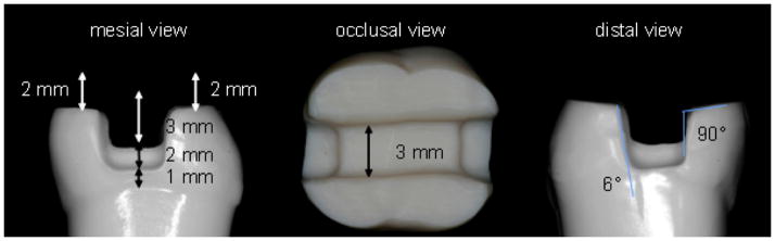
Occlusal and proximal views of the standardised preparation on a typodont mandibular molar.
Fabrication of the all-ceramic restorations
Impressions of the prepared teeth were taken according to the double-mixing technique using a vinyl-polysiloxane material (Affinis, Coltène/Whaledent AG, Altstätten, Switzerland). A combination of a regular-body material (Affinis Precious regular body, Coltène/Whaledent AG, Altstätten, Switzerland) and a heavy body material with a higher consistency (Affinis heavy body, Coltène/Whaledent AG, Altstätten, Switzerland) was used. The regular body material was applied to the prepared tooth with a syringe. The heavy body material was put on a perforated custom-made plastic tray (Minitrays, Hager & Werken GmbH, Duisburg, Germany); the surface of the tray was treated with an adhesive (Coltene Adhesive AC, Coltène/Whaledent AG, Altstätten, Switzerland). The tray was then placed parallel to the tooth axis, and was held without pressure until the impression material was set. The impressions were poured with a scannable Type IV gypsum material (Esthetic-base gold, Dentona AG, Dortmund, Germany). Cavity surfaces were lined (approximately 10 μm) with die spacer (Purargent, DUS Dental, Richmond, Canada), thereby maintaining 1.5 mm distance to the marginal areas. All restorations were produced in a full-anatomic contour and were glazed for surface characterization without any additional veneer application. All restorations were fabricated by the respective manufacturer of the all-ceramic material (Ivoclar Vivadent, Schaan, Liechtenstein and Vita Zahnfabrik, Bad Säckingen, Germany).
Onlays were manufactured using a pressable lithium disilicate glass-ceramic (Group IP, IPS e.max Press, Ivoclar-Vivadent Schaan, Liechtenstein). The final wax restoration was invested in IPS PressVEST Speed (Ivoclar Vivadent, Schaan, Liechtenstein) investment material and pressed with IPS e.max Press LT A2 (Ivoclar Vivadent, Schaan, Liechtenstein) ingots in a press furnace EP 600 (Ivoclar Vivadent, Schaan, Liechtenstein) using the firing parameters recommended by the manufacturer. The programed press temperature was 915°C and the dwell time was 15 mins. The press procedure was activated at the press temperature and the then viscous glass-ceramic ingot was pressed (0.4 MPa) into the mold. The press process was performed in a vacuum; both the pressure and vacuum were maintained until the completion of the dwell time. The glass-ceramic restorations were devested by immersing pressed parts in an aqueous solution containing 0.6% hydrofluoric acid and 1.7% sulphuric acid followed by blasting with Al2O3 particles (100 μm at 0.2 MPa pressure). The devested restorations were then glazed with IPS e.max Ceram Glaze Liquid (Ivoclar Vivadent, Schaan, Liechtenstein). Two glaze firings were performed in a Programat P200 furnace (Ivoclar Vivadent, Schaan, Liechtenstein) at 770°C with a dwell time of 1:30 mins and 1 min, respectively.
A pressable fine-structured feldspar ceramic material was used in group VP (VITA PM9, VITA Zahnfabrik, Bad Säckingen, Germany). The restorations were modeled with YETI dental wax (Yeti Detantalprodukte, Engen, Germany) according to the situation model. The wax models were invested in Vita PM9 investment material (VITA Zahnfabrik, Bad Säckigen, Germany), a grafite-free, phosphate-bonded investment material for speed preheating of PM9. The proportions were 80% mixing liquid (VITA PM9 investment material mixing liquid, VITA Zahnfabrik, Bad-Säckigen, Germany) and 20% distilled water. The investment ring was preheated at 850°C for 75 mins and then the restorations were pressed with 2x PM9 Pellet 1M2PT ingots (VITA Zahnfabrik, Bad Säckigen, Germany) in an EP 600 furnace (Ivoclar Vivadent, Schaan, Liechtenstein) following manufacturer’s instructions. The press temperature was 1000°C and the dwell time was 20 mins. Again, the press procedure was carried out in vacuum and the pressure applied was 0.4 MPa. Finally, a glaze firing was performed with Vita Akzent glazing and staining materials (VITA Zahnfabrik, Bad-Säckigen, Germany) and individual firing trays were used in order to avoid the deformation of the restorations during firing. The glaze temperature was 910°C and the dwell time 1 min.
Restorations from group IC (IPS e.max CAD, Ivoclar Vivadent, Schaan, Liechtenstein) were designed and milled with a CAD/CAM system (Cerec inLab 3D Software V3.01, Sirona, Bensheim, Germany) from presintered lithium disilicate glass-ceramic blocks (IPS e.max CAD, Ivoclar Vivadent, Schaan, Liechtenstein). Final sintering of IPS e.max CAD restorations was performed after the milling procedure following the manufacturer’s instruction. The sintering temperature was 840 °C and the dwell time was 7 mins. Glazing (IPS e.max Ceram Glaze Paste Ivoclar Vivadent, Schaan, Liechtenstein) with a standard cooling procedure was applied as final treatment.
Adhesive placement of all-ceramic restorations
The intaglio surfaces of the restorations were etched with 4.9% hydrofluoric acid (IPS Ceramic Etching gel, Ivoclar Vivadent, Schaan, Liechtenstein; IPS e.max Press and IPS e.max CAD: 20 seconds; VITA PM9: 60 seconds) and were then rinsed with water for 60 seconds and air dried. Subsequently, a silane coupling agent (Monobond S, Ivoclar Vivadent, Schaan, Lichtenstein) followed by a light curing bonding agent (Heliobond, Ivoclar Vivadent, Schaan, Lichtenstein) was applied. Teeth were etched (30 seconds for enamel, 15 seconds for dentin) with 37% phosphoric acid. Tooth surfaces were conditioned with Syntac Primer, Adhesive and Heliobond (Ivoclar Vivadent, Schaan, Lichtenstein). Restorations were then adhesively cemented with a dual-polymerizing resin composite Variolink II (Ivoclar Vivadent, Schaan Lichtenstein). All cementation procedures followed the manufacturer’s instruction. Restorations were seated with finger pressure. Any excess cement was removed and glycerine gel (Liquid Strip, Ivoclar Vivadent, Schaan Lichtenstein) was applied at the marginal area. All surfaces of the restorations (occlusal, mesial, distal, lingual and buccal) were then light-cured with a polymerization lamp with a light wavelength of 480 nm and a power of 1110 mW/cm2 (Optilux 501, Kerr, Orange, USA) for 40 seconds. Excess cement was removed with a scalpel No. 15 and flexible discs (SoftLex Pop-On, 3M Medica, St. Paul, USA) under magnification loupes (4.5 magnification, Zeiss Meditec loupe system; Carl Zeiss, Jena, Germany).
Thermo-mechanical fatigue
All specimens were subjected to 1.2 million cycles of thermo-mechanical fatigue in a computer-controlled chewing simulator (Willytec, Munich, Germany) under clinically relevant conditions. A load of 98 N was applied in the center of the occlusal surface using a ceramic antagonist ball (r= 3 mm, Steatit, Hoechst Ceram Tec, Wunsiedel, Germany) 28. A sliding load with a vertical movement of 6 mm, a horizontal movement of 0.5 mm and a frequency of 1.6 Hz was applied. Simultaneously, specimens were subjected to thermocycling between 5°C and 55°C for 60 seconds each with a dwell time of 12 seconds, maintained by a thermostatically controlled liquid circulator (Haake, Karlsruhe, Germany). A total of 5208 thermal cycles were performed during the course of 1.2 million cyclic fatigue.
Marginal and internal fit evaluation
To examine the marginal fit with the replica technique, impressions of all-ceramic restorations were taken before and after cementation, as well as after exposure to thermo-mechanical fatigue. Before cementation, the partial coverage restorations were held in place with a small amount of Variolink II Try-in paste during the impression procedure. A poly-vinylsiloxane impression material (Dimension Garant L and Permagum Putty Soft, 3M ESPE, Seefeld, Germany) using the Putty-Soft-Wash-Technique was applied. For the fabrication of the replicas, the impressions were poured with an epoxy resin material (Alpa-Pur, Alpina Technische Produkte GmbH, Geretsried, Germany) according to the manufacturer’s instruction.
After exposure to the chewing simulator, eight specimens from each group were used for internal fit evaluation. Teeth were embedded in acrylic resin (Technovit 4000, Kulzer, Wehrheim, Germany) and sectioned with a water cooled low speed diamond saw (Exact Apparatebau, Norderstedt, Germany). Four samples were sectioned bucco-lingually and another set of four samples was sectioned mesio-distally in three planes. Sectioned surfaces were then polished with a 400 grit silicon carbide paper (Bühler GmbH, Düsseldorf, Germany) (Figure 2, 3).
Fig. 2.
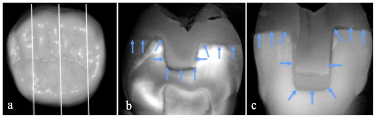
Internal fit evaluation. (a) Overview of the three bucco-lingual sections planes within the samples. (b) Localisation of the 11 preselected internal fit measuring points in the median section. (c) Localisation of the 11 preselected internal fit measuring points in the right lateral section.
Fig. 3.
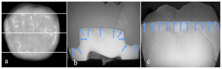
Internal fit evaluation. (a) Overview of the three mesio-distal sections planes within the samples. (b) Localisation of the 11 preselected internal fit measuring points in the median section (c) Localisation of the 11 preselected internal fit measuring points in the lingual section.
Marginal and internal fit discrepancies were analysed with a stereo microscope, (Zeiss Axioskop Zeiss, Oberkochen, Germany), a 3 CCD-color videocamera (Sony 3CCD, Sony, Köln, Germany), and a compatible personal computer with the Microsoft NT 4.0 operating system and an image analysis program (cell* Imaging Software for Life Sciences Microscopy, Olympus Soft Imaging Solutions, Münster, Germany). Marginal and internal fit discrepancies were measured on the screen of the PC with a 200x magnification. Horizontal and vertical rulers with micrometer scaling implemented by the software were used to determine the distance between each measurement. Individual marginal fit measurements were carried out by marking the edge of the preparation margin and the margin of the restoration. Two marked points were related by the software and the distance was calculated (Figure 4). All epoxy replicas (n= 16 specimens per group) were oriented vertically to the cement interface and marginal discrepancies were measured at 100 intervals of 100 μm. Since the size of the natural human molars varied, the total number of the measurements was in the range of 400–500 per tooth. The measurements of the internal fit were conducted (n= 16 specimens per group) at a total of 66 preselected locations in bucco-lingual (Fig. 2) and mesio-distal dimensions (Fig. 3). The above mentioned method was applied 29. All measurements were performed by one operator.
Fig. 4.

Schematic illustration of the marginal gap measurement. Two marked points (edge of the preparation margin and the margin of the restoration) were related by a software and the distance was calculated.
Based on the average values of marginal and internal fit, least-square means with 95% confidence intervals were computed for each group, before and after cementation as well as after fatigue.
Two linear models with GEE techniques were used accounting for repeated measurements. The continuous outcome marginal gap was modeled as a linear function of group, phase and interaction as explanatory variables. The continuous outcome internal fit was modeled as a linear function of group. Least-square means with a 95% confidence interval were calculated and graphically displayed. A subanalysis was performed and the p-values were adjusted by the method of Holm at a significance level of 0.05. All computations were performed with the statistical software SAS system version 9.1, Institute Inc., Cary, NC, USA.
Results
The least square means of marginal fit in μm and the 95% confidence interval of groups IP, VP and IC are displayed in Table 1 and depicted in Figure 5. Statistical comparisons of marginal gap values before and after cementation as well as after fatigue are shown in Table 2. Before cementation, restorations of group VP revealed significantly lower marginal gap values than IP and IC restorations (p = 0.0018), whereas the difference between groups IP and IC was not significant (p = 0.2988). Cementation increased the marginal gap of partial coverage restorations significantly regardless of the fabrication technique and all-ceramic material evaluated (Table 2). After cementation, significant differences were found between all groups. Marginal gap values of IP restorations were significantly higher than IC (p = 0.0243) and VP (p = 0.0018) restorations. VP onlays revealed significantly smaller marginal gap values than IC onlays (p = 0.0018). After thermo-mechanical fatigue, no significant differences were found between the marginal gap values of all test groups (p > 0.05). A significant increase in marginal gap values was observed in all groups after cementation of the restorations (p < 0.05), whereas no difference was found between before and after fatigue exposure (p > 0.05) (Table 3).
Table 1.
Descriptive analysis of marginal fit values of groups IPS e.max Press, IPS e.max CAD and VITA PM9, before and after cementation, as well as after fatigue
| Least square means (μm) | |||||||||
|---|---|---|---|---|---|---|---|---|---|
| Group | IP | IC | VP | ||||||
| Phase | Estimate | Confidence Intervals | Estimate | Confidence Intervals | Estimate | Confidence Intervals | |||
| Before cementation | 45.51 | 42.04 | 48.98 | 50.09 | 47.18 | 52.99 | 35.30 | 33.31 | 37.29 |
| After cementation | 62.86 | 57.42 | 68.31 | 54.05 | 52.26 | 55.84 | 48.55 | 46.62 | 50.49 |
| After fatigue | 58.59 | 51.78 | 65.41 | 50.54 | 48.63 | 52.46 | 50.98 | 47.70 | 54.27 |
Fig. 5.

Least square means and confidence intervals (CI) of the marginal gap values in mm (IP = IPS e.max Press, IC = IPS e.max CAD, VP = VITA PM9, phase 0 = before cementation, phase 1 = after cementation, phase 2 = after fatigue).
Table 2.
Comparison of marginal fit of the groups IPS e.max Press, IPS e.max CAD and VITA PM9 between the three phases within each group; statistical significances (p< 0.05) are highlighted.
| group | phase | _phase | Estimate | Local p-value | Adjusted p-value |
|---|---|---|---|---|---|
| IPS e.max Press | before cementation | after cementation | −17.35 | < .0001 | 0.0018 |
| IPS e.max Press | before cementation | after fatigue | −13.08 | < .0001 | 0.0018 |
| IPS e.max Press | after cementation | after fatigue | 4.27 | 0.0771 | 0.3084 |
| IPS e.max CAD | before cementation | after cementation | −3.96 | 0.0022 | 0.0220 |
| IPS e.max CAD | before cementation | after fatigue | −0.46 | 0.7997 | 0.9164 |
| IPS e.max CAD | after cementation | after fatigue | 3.51 | 0.0064 | 0.0512 |
| VITA PM9 | before cementation | after cementation | −13.25 | < .0001 | 0.0018 |
| VITA PM9 | before cementation | after fatigue | −15.70 | < .0001 | 0.0018 |
| VITA PM9 | after cementation | after fatigue | −2.45 | 0.1967 | 0.5901 |
Table 3.
Comparison of marginal fit of groups IPS e.max Press, IPS e.max CAD and VITA PM9 at the three phases; statistical significances (p< 0.05) are highlighted.
| group | _group | phase | Estimate | Local p-values | Adjusted p-values |
|---|---|---|---|---|---|
| IPS e.max Press | IPS e.max CAD | before cementation | −4.47 | 0.0498 | 0.2988 |
| IPS e.max Press | VITA PM9 | before cementation | 10.78 | < .0001 | 0.0018 |
| IPS e.max CAD | VITA PM9 | before cementation | 15.25 | < .0001 | 0.0018 |
| IPS e.max Press | IPS e.max CAD | after cementation | 8.59 | 0.0027 | 0.0243 |
| IPS e.max Press | VITA PM9 | after cementation | 13.90 | < .0001 | 0.0018 |
| IPS e.max CAD | VITA PM9 | after cementation | 5.32 | < .0001 | 0.0018 |
| IPS e.max Press | IPS e.max CAD | after fatigue | 8.50 | 0.0188 | 0.1316 |
| IPS e.max Press | VITA PM9 | after fatigue | 7.15 | 0.0602 | 0.3010 |
| IPS e.max CAD | VITA PM9 | after fatigue | −1.35 | 0.4582 | 0.9164 |
Least square means of the internal fit values in μm and confidence intervals are displayed in Table 4 and Figure 6. The CAD/CAM fabricated IC restorations revealed significantly higher internal fit values than press fabricated IP (p = 0.0107) and VP (p < 0.0001) restorations. The press restorations IP and VP revealed comparable internal fit results (p = 0.3676) (Table 5).
Table 4.
Descriptive analysis of the internal fit values of groups IPS e.max Press, IPS e.max CAD and VITA PM9.
| Least square means (μm) | |||||||||
|---|---|---|---|---|---|---|---|---|---|
| Group | IP | IC | VP | ||||||
| Estimate | Confidence Intervals | Estimate | Confidence Intervals | Estimate | Confidence Intervals | ||||
| Internal fit | 66.90 | 57.45 | 76.36 | 103.37 | 96.66 | 110.08 | 58.31 | 42.19 | 74.43 |
Fig. 6.

Least square means in μm and confidence intervals of the internal fit values (IPS = e.max Press, IPS = e.max CAD, VP = VITA PM9).
Table 5.
Comparison of internal fit between the groups IPS e.max Press, IPS e.max CAD and VITA PM9; statistical significances (p< 0.05) are highlighted.
| group | _group | Estimate | Adjusted p-value | Confidence Intervals | |
|---|---|---|---|---|---|
| IPS e.max Press | IPS e.max CAD | −36.47 | < .0001 | −48.06 | −24.88 |
| IPS e.max Press | VITA PM9 | 8.59 | 0.3676 | −10.10 | 27.28 |
| IPS e.max CAD | VITA PM9 | 45.06 | < .0001 | 27.60 | 62.52 |
Discussion
The aim of this study was to compare the marginal and internal fit of different all-ceramic molar onlay restorations before and after luting as well as after thermo-mechanical fatigue in a dual-axis chewing simulator. Additionally, the effect of different fabrication techniques (CAD-CAM vs. press) and materials (PM9 vs. IPS.emax Press) on the marginal adaptation and internal fit was investigated. The null hypothesis that there is no difference exists in marginal and internal fit of onlay restorations with different all-ceramic materials and fabrication techniques was rejected, while the hypothesis that fatigue has no influence on the marginal fit of the restorations was accepted.
Natural human teeth were used in the present study for marginal and internal fit evaluation of all-ceramic onlay restorations to provide highest clinical relevance with respect to adhesive cementation and bonding protocols as well as preparation designs 30. The preparation geometry with occlusal butt joint margins was designed according to preparation guidelines for all-ceramic partial coverage restorations mentioned in the literature 31, 32. The occlusal reduction and occlusal box depth dimensions were prepared to simulate extensive tooth structure destruction 33, 34.
The replica technique used in the present study is a non-destructive method for quantitative analysis of the marginal accuracy, leaving the tooth intact and allowing for the reproducibility of measurements at different time intervals. This technique was used in several in vitro and in vivo studies and comparisons of laboratory and clinical results, and can therefore be considered as a well documented procedure 11, 30, 35, 36, 37. With this technique, the marginal accuracy can be evaluated at the entire circumference of the restoration or at preselected points 30, 35, 38. The clinically acceptable marginal gap values for dental restorations vary substantially between various studies and range from 20 to 150 μm 39–41. The mean marginal discrepancies of the all-ceramic partial coverage restorations of the present study were 35–50 μm before cementation, 49–63 μm after cementation, and 51–59 μm after thermo-mechanical fatigue. These values were all within the clinically acceptable range.
Many variables such as tooth preparation design, location and number of measuring points, measuring techniques, type of resin cement and restoration fabrication method will influence the marginal discrepancy value 27. Hence all these factors should be considered when different studies are compared 42. The number of measurements that was applied for marginal fit evaluation in the present study surmounted the required minimum of examination points (n= 50) by substantial margin 27.
Values reported in the literature for marginal discrepancies of partial coverage restorations before cementation are scarce. Results of marginal gap analysis for the same preparation design on upper molars averaged 50 μm and are comparable with the results of the present study 35. For CAD/CAM fabricated restorations, the values reported in the literature before cementation range from 50 to 60 μm 43–44, 45. These values are in accordance with those of the present study, but a direct comparison should be assessed only with caution as different types of preparation designs and preceding generations of the Cerec system were implemented. The mean marginal fit values of the presently investigated heat press and CAD/CAM fabricated restorations increased significantly after cementation. Factors like the viscosity of the luting agent, filler particle size, as well as the preparation design may influence the marginal fit of restorations after their cementation 45, 46. The marginal gap values of the present study are comparable to other investigations on heat-pressed all-ceramic restorations. Mean marginal gaps of IPS e.max Press and IPS-Empress restorations after cementation were 60 μm and 52 μm, respectively 47. Slightly higher values between 78 and 99 μm were reported in other studies for IPS e.max Press restorations and modified partial coverage preparation designs 30, 35.
Only limited studies on CAD/CAM fabricated partial coverage restorations are currently available for reference. Cerec 2 and Cerec 3 fabricated full-coverage all-ceramic onlays revealed mean marginal gaps of 80 μm to 85 μm 11, 47. In the present study, marginal fit values of CAD/CAM fabricated IPS e.max CAD onlay restorations averaged only 54 μm. However, comparisons between different Cerec versions have to be carefully assessed since the software abilities and milling procedures have improved significantly.
The dual-axis chewing simulator with a sliding component corresponded as closely as possible to the physiological intraoral condition and was used in the present study for the artificial thermo-mechanical ageing of the tested restorations. Steatite ceramic balls served as antagonists, as steatite has been proven to be a suitable substitute material for enamel 48–50. The diameter of the identer was 6 mm, therefore comparable to a molar cusp 28. The applied load was 98 N, which adequatley simulates the physiological biting force of posterior teeth 51, 52. The simulated five-year ageing of the all-ceramic partial coverage restorations had no effect on the marginal fit. These findings are in accordance with the results of previous studies 30, 47. In contrast to that, several in vitro 35, 53 and in vivo studies 54, 55 reported a decrease in marginal accuracy of differently designed partial coverage ceramic restorations over time. The variation in preparation geometry is mentioned as possible explanation 35. In most of these studies, the restorations revealed margins in the occlusal area that were directly exposed to wear by load application. An increased wear was observed in occlusal margins during clinical evaluation, while ditching and chipping in the unloaded, proximal areas were rarely noted 56. Moreover, composite surface breakdown and microcrack formation within the adjacent tooth structures and ceramic were also mainly reported in the occlusal contact area 46. The preparation design of the present study revealed no marginal exposure within the occlusal surface. All preparation margins were restricted to the buccal, lingual and proximal surfaces. Therefore, increased marginal discrepancies due to marginal chipping were not experienced. The fact that proximal restoration margins were placed 1 mm above the cementoenamel junction, thus were within enamel, may explain the absence of marginal deterioration in these areas after artificial thermo-mechanical ageing. It is well known that the adhesive bond in enamel is more durable than that in dentin 57.
Although an adequate internal adaptation of a restoration is considered as a decisive factor for longevity, threshold values for internal fit dimensions have not been determined 58. For the evaluation of internal fit, the presently applied destructive measuring techniques with multiple section planes is the most commonly used method. The in-vitro fit of laboratory produced sintered porcelain partial coverage restorations has been reported with a range from 91 to 308 μm 59. The internal fit values of all test groups of the present study were within the limits reported in the literature 21, 29, 60. The least square means of the internal fit values of the IPS e.max Press, VITA PM9 and IPS e.max CAD groups were 67, 58, and 103 μm, respectively. No significant difference was found between the IPS e.max Press and VITA PM9 groups. The differences in all-ceramic material composition and microstructure, manufacturing methods and parameters did not lead to significant differences in the internal fit of heat-press fabricated restorations.
However, CAD/CAM manufactured restorations exhibited significantly larger internal fit values than the press groups. The more favourable interal fit values that were observed in the present study could also be attributed to the differences in the heat press versus the CAD/CAM fabrication techniques. For the heat press technique, one single layer of die spacer material (20 μm) was applied on the prepared tooth, whereas the luting space and adhesive gap given by default for the CAD/CAM system was 50 μm.
Significantly higher internal discrepancies of lingual onlay restorations were also reported in a recent study when CAD/CAM IPS e.max CAD restorations were compared to heat press IPS e.max Press restorations 61. Software limitations in designing restorations and hardware limitiations within scanning equipement and the milling machine are possible shortcomings in the CAD/CAM technique. Moreover, a size dicrepancy of the cutting tools tooth preparation geometry may cause misfit and contribute to inferior marginal properties of the computer milled ceramic restorations.
With the advancement of software programs, design algorithms, and milling units, the CAD/CAM accuracy has been improved. Moreover, the expertise with the Cerec device and the clinical skills of the operator during preparation also impact the outcome of CAD/CAM fabricated restoration.
There are several limitations of this study. The evaluation of marginal and internal results was restricted to the preselected measure points in two dimensions. The impression replica technique is less cost-effective and more time consuming than the direct-view technique. Moreover, the chance of error accumulation that may result from multiple procedures coud possibly affect the accuracy of results. In addition, the selection of measuring points of the marginal opening can be difficult as the differentiation between tooth structure, cement and the most apical part of the preparation margin can be tough to identify. Altough the impression replica tehcnique has contraints and inherent errors, it is the only technique that allows long-term analyses and can also be applied in clinical circumstances.
Our results are only applicable to the all-ceramic system and fabrication techniques as well as preparation design evaluated. Geometrically simplified, non-retentive preparation designs may reveal more favourable outcomes and are the aim of future research.
Conclusions
Mean marginal gap values of all onlay restorations before and after cementation as well as after thermo-mechanical fatigue were within the clinically acceptable range. Marginal fit of onlay restorations was neither affected by the heat-press and CAD/CAM fabrication technique nor by the different all-ceramic materials. The press fabrication technique of all-ceramic onlays resulted in significantly better internal fit values compared to the CAD/CAM technique. The interaction of internal fit and cementation surface crack initiation needs to be addressed in further research. Prospective long-term studies are necessary to evaluate the clinical outcome of different fabrication techniques for the all-ceramic onlay indication.
Acknowledgments
This study was supported by Ivoclar Vivadent, Schaan, Liechtenstein and Vita Zahnfabirk, Bad Säckingen, Germany and the United States National Institute of Dental and Craniofacial Research (Grant 2R01 DE017925).
Footnotes
The authors declare that they have no conflict of interest.
References
- 1.Manhart J, Chen H, Hamm G, Hickel R. Buonocore Memorial Lecture. Review of the clinical survival of direct and indirect restorations in posterior teeth of the permanent dentition. Oper Dent. 2004;29:481–508. [PubMed] [Google Scholar]
- 2.Edelhoff D, Sorensen JA. Tooth structure removal associated with various preparation designs for posterior teeth. Int J Perio Rest Dent. 2002;22:241–9. [PubMed] [Google Scholar]
- 3.van Dijken JW, Hasselrot L. A prospective 15-year evaluation of extensive dentin-enamel-bonded pressed ceramic coverages. Dent Mater. 2010;26:929–39. doi: 10.1016/j.dental.2010.05.008. [DOI] [PubMed] [Google Scholar]
- 4.Stoll R, Sieweke M, Pieper K, Stachniss V, Schulte A. Longevity of cast gold inlays and partial crowns-a retrospective study at a dental school clinic. Clin Oral Investig. 1999;3:100–4. doi: 10.1007/s007840050086. [DOI] [PubMed] [Google Scholar]
- 5.Studer SP, Wettstein F, Lehner C, Zullo TG, Scharer P. Long-term survival estimates of cast gold inlays and onlays with their analysis of failures. J Oral Rehabil. 2000;27:461–72. doi: 10.1046/j.1365-2842.2000.00540.x. [DOI] [PubMed] [Google Scholar]
- 6.Kelly JR, Benetti P. Ceramic materials in dentistry: historical evolution and current practice. Aust Dent J. 2011;56 (Suppl 1):84–96. doi: 10.1111/j.1834-7819.2010.01299.x. [DOI] [PubMed] [Google Scholar]
- 7.Rekow ED, Silva NR, Coelho PG, Zhang Y, Guess P, Thompson VP. Performance of Dental Ceramics: Challenges for Improvement. J Dent Res. 2011;90:937–52. doi: 10.1177/0022034510391795. [DOI] [PMC free article] [PubMed] [Google Scholar]
- 8.Guess PC, Selz CF, Steinhart YN, Stampf S, Strub JR. Prospective clinical split-mouth study of pressed and CAD/CAM all-ceramic partial-coverage restorations: 7-year results. Int J Prosthodont. 2013;26:21–5. doi: 10.11607/ijp.3043. [DOI] [PubMed] [Google Scholar]
- 9.Beier US, Kapferer I, Burtscher D, Giesinger JM, Dumfahrt H. Clinical performance of all-ceramic inlay and onlay restorations in posterior teeth. Int J Prosthodont. 2012;25:395–402. [PubMed] [Google Scholar]
- 10.Heintze SD. Systematic Review: I. The correlation between laboratory test on marginal quality and bond strength. II. The correlation between marginal quality and clinical outcome. J Adhes Dent. 2007;9:77–106. [PubMed] [Google Scholar]
- 11.Denissen H, Dozic A, van der Zel J, van Waas M. Marginal fit and short-term clinical performance of porcelain-veneered CICERO, CEREC, and Procera onlays. J Prosthet Dent. 2000;84:506–13. doi: 10.1067/mpr.2000.110258. [DOI] [PubMed] [Google Scholar]
- 12.Felden A, Schmalz G, Hiller KA. Retrospective clinical study and survival analysis on partial ceramic crowns: results up to 7 years. Clin Oral Investig. 2000;4:199–205. doi: 10.1007/s007840000082. [DOI] [PubMed] [Google Scholar]
- 13.Krämer N, Frankenberger R. Clinical performance of bonded leucite-reinforced glass ceramic inlays and onlays after eight years. Dent Mater. 2005;21:262–71. doi: 10.1016/j.dental.2004.03.009. [DOI] [PubMed] [Google Scholar]
- 14.Silva NR, de Souza GM, Coelho PG, Stappert CF, Clark EA, Rekow ED, et al. Effect of water storage time and composite cement thickness on fatigue of a glass-ceramic trilayer system. Journal of biomedical materials research. Part B, Applied biomaterials. 2008;84:117–23. doi: 10.1002/jbm.b.30851. [DOI] [PubMed] [Google Scholar]
- 15.Deng Y, Miranda P, Pajares A, Guiberteau F, Lawn BR. Fracture of ceramic/ceramic/polymer trilayers for biomechanical applications. J Biomed Mater Res A. 2003;67:828–33. doi: 10.1002/jbm.a.10161. [DOI] [PubMed] [Google Scholar]
- 16.Coelho P, Silva N, Bonfante E, Guess PC, Rekow ED, Thompson V. Fatigue testing of two porcleain zirconia all-ceramic crown systems. Dental Materials. 2009;25:1122–27. doi: 10.1016/j.dental.2009.03.009. [DOI] [PubMed] [Google Scholar]
- 17.Zhang Y, Kim JW, Bhowmick S, Thompson VP, Rekow ED. Competition of fracture mechanisms in monolithic dental ceramics: flat model systems. Journal of biomedical materials research. Part B, Applied biomaterials. 2009;88:402–11. doi: 10.1002/jbm.b.31100. [DOI] [PMC free article] [PubMed] [Google Scholar]
- 18.Ma L, Guess PC, Zhang Y. Load-bearing properties of minimal-invasive monolithic lithium disilicate and zirconia occlusal onlays: Finite element and theoretical analyses. Dent Mater. 2013;29:742–51. doi: 10.1016/j.dental.2013.04.004. [DOI] [PMC free article] [PubMed] [Google Scholar]
- 19.Chai J, Takahashi Y, Sulaiman F, Chong K, Lautenschlager EP. Probability of fracture of all-ceramic crowns. Int J Prosthodont. 2000;13:420–4. [PubMed] [Google Scholar]
- 20.Deng Y, Lawn BR, Lloyd IK. Characterization of damage modes in dental ceramic bilayer structures. J Biomed Mater Res. 2002;63:137–45. doi: 10.1002/jbm.10091. [DOI] [PubMed] [Google Scholar]
- 21.Karakaya S, Sengun A, Ozer F. Evaluation of internal adaptation in ceramic and composite resin inlays by silicon replica technique. J Oral Rehabil. 2005;32:448–53. doi: 10.1111/j.1365-2842.2005.01443.x. [DOI] [PubMed] [Google Scholar]
- 22.Qasim T, Bush MB, Hu X, Lawn BR. Contact damage in brittle coating layers: influence of surface curvature. Journal of biomedical materials research. Part B, Applied biomaterials. [Research Support, N.I.H., Extramural Research Support, Non-U.S. Gov’t Research Support, U.S. Gov’t, P.H.S] 2005;73:179–85. doi: 10.1002/jbm.b.30188. [DOI] [PubMed] [Google Scholar]
- 23.Kim JW, Thompson VP, Rekow ED, Jung YG, Zhang Y. Fracture Modes in Curved Brittle Layers Subject to Concentrated Cyclic Loading in Liquid Environments. J Mater Res. 2009;24:1075–81. doi: 10.1557/jmr.2009.0081. [DOI] [PMC free article] [PubMed] [Google Scholar]
- 24.Stappert CF, Baldassarri M, Zhang Y, Stappert D, Thompson VP. Contact fatigue response of porcelain-veneered alumina model systems. Journal of biomedical materials research. Part B, Applied biomaterials. 2011 doi: 10.1002/jbm.b.31977. [DOI] [PubMed] [Google Scholar]
- 25.Federlin M, Krifka S, Herpich M, Hiller KA, Schmalz G. Partial ceramic crowns: influence of ceramic thickness, preparation design and luting material on fracture resistance and marginal integrity in vitro. Oper Dent. 2007;32:251–60. doi: 10.2341/06-70. [DOI] [PubMed] [Google Scholar]
- 26.Ilie N, Kunzelmann KH, Hickel R. Evaluation of micro-tensile bond strengths of composite materials in comparison to their polymerization shrinkage. Dent Mater. 2006;22:593–601. doi: 10.1016/j.dental.2005.05.014. [DOI] [PubMed] [Google Scholar]
- 27.Nawafleh NA, Mack F, Evans J, Mackay J, Hatamleh MM. Accuracy and reliability of methods to measure marginal adaptation of crowns and FDPs: a literature review. J Prosthodont. 2013;22:419–28. doi: 10.1111/jopr.12006. [DOI] [PubMed] [Google Scholar]
- 28.Kern M, Strub JR, Lu XY. Wear of composite resin veneering materials in a dual-axis chewing simulator. J Oral Rehabil. 1999;26:372–8. doi: 10.1046/j.1365-2842.1999.00416.x. [DOI] [PubMed] [Google Scholar]
- 29.Addi S, Hedayati-Khams A, Poya A, Sjogren G. Interface gap size of manually and CAD/CAM-manufactured ceramic inlays/onlays in vitro. J Dent. 2002;30:53–8. doi: 10.1016/s0300-5712(01)00059-8. [DOI] [PubMed] [Google Scholar]
- 30.Stappert CF, Abe P, Kurths V, Gerds T, Strub JR. Masticatory fatigue, fracture resistance, and marginal discrepancy of ceramic partial crowns with and without coverage of compromised cusps. J Adhes Dent. 2008;10:41–8. [PubMed] [Google Scholar]
- 31.Federlin M, Sipos C, Hiller KA, Thonemann B, Schmalz G. Partial ceramic crowns. Influence of preparation design and luting material on margin integrity--a scanning electron microscopic study. Clin Oral Investig. 2005;9:8–17. doi: 10.1007/s00784-004-0276-1. [DOI] [PubMed] [Google Scholar]
- 32.Ahlers MO, Morig G, Blunck U, Hajto J, Probster L, Frankenberger R. Guidelines for the preparation of CAD/CAM ceramic inlays and partial crowns. Int J Comput Dent. 2009;12:309–25. [PubMed] [Google Scholar]
- 33.Banks RG. Conservative posterior ceramic restorations: a literature review. J Prosthet Dent. 1990;63:619–26. doi: 10.1016/0022-3913(90)90316-5. [DOI] [PubMed] [Google Scholar]
- 34.Krifka S, Anthofer T, Fritzsch M, Hiller KA, Schmalz G, Federlin M. Ceramic inlays and partial ceramic crowns: influence of remaining cusp wall thickness on the marginal integrity and enamel crack formation in vitro. Oper Dent. 2009;34:32–42. doi: 10.2341/08-34. [DOI] [PubMed] [Google Scholar]
- 35.Stappert CF, Denner N, Gerds T, Strub JR. Marginal adaptation of different types of all-ceramic partial coverage restorations after exposure to an artificial mouth. Br Dent J. 2005;199:779–83. doi: 10.1038/sj.bdj.4813036. discussion 7. [DOI] [PubMed] [Google Scholar]
- 36.Frankenberger R, Kramer N, Lohbauer U, Nikolaenko S, Reich S. Marginal integrity: Is the clinical performance of bonded restorations predictable in vitro? J Adhes Dent. 2007;9:107–16. [PubMed] [Google Scholar]
- 37.Bindl A, Mormann WH. Clinical and SEM evaluation of all-ceramic chair-side CAD/CAM-generated partial crowns. Eur J Oral Sci. 2003;111:163–9. doi: 10.1034/j.1600-0722.2003.00022.x. [DOI] [PubMed] [Google Scholar]
- 38.Dietschi D, Maeder M, Holz J. In vitro evaluation of marginal fit and morphology of fired ceramic inlays. Quint Int. 1992;23:271–8. [PubMed] [Google Scholar]
- 39.McLean JW, von Fraunhofer JA. The estimation of cement film thickness by an in vivo technique. Br Dent J. 1971;131:107–11. doi: 10.1038/sj.bdj.4802708. [DOI] [PubMed] [Google Scholar]
- 40.Karlsson S. The fit of Procera titanium crowns. An in vitro and clinical study. Acta Odontol Scand. 1993;51:129–34. doi: 10.3109/00016359309041158. [DOI] [PubMed] [Google Scholar]
- 41.Molin MK, Karlsson SL, Kristiansen MS. Influence of film thickness on joint bend strength of a ceramic/resin composite joint. Dent Mater. 1996;12:245–9. doi: 10.1016/s0109-5641(96)80030-3. [DOI] [PubMed] [Google Scholar]
- 42.Keshvad A, Hooshmand T, Asefzadeh F, Khalilinejad F, Alihemmati M, Van Noort R. Marginal gap, internal fit, and fracture load of leucite-reinforced ceramic inlays fabricated by CEREC inLab and hot-pressed techniques. J Prosthodont. 2011;20:535–40. doi: 10.1111/j.1532-849X.2011.00745.x. [DOI] [PubMed] [Google Scholar]
- 43.Inokoshi S, Van Meerbeek B, Willems G, Lambrechts P, Braem M, Vanherle G. Marginal accuracy of CAD/CAM inlays made with the original and the updated software. J Dent [Comparative Study In Vitro] 1992;20:171–7. doi: 10.1016/0300-5712(92)90132-v. [DOI] [PubMed] [Google Scholar]
- 44.Mormann WH, Schug J. Grinding precision and accuracy of fit of CEREC 2 CAD-CIM inlays. Journal of the American Dental Association. 1997;128:47–53. doi: 10.14219/jada.archive.1997.0025. [DOI] [PubMed] [Google Scholar]
- 45.Martin N, Jedynakiewicz NM. Interface dimensions of CEREC-2 MOD inlays. Dental materials : official publication of the Academy of Dental Materials. 2000;16:68–74. doi: 10.1016/s0109-5641(99)00089-5. [DOI] [PubMed] [Google Scholar]
- 46.Kramer N, Frankenberger R. Leucite-reinforced glass ceramic inlays after six years: wear of luting composites. Oper Dent. 2000;25:466–72. [PubMed] [Google Scholar]
- 47.Stappert CF, Chitmongkolsuk S, Silva NR, Att W, Strub JR. Effect of mouth-motion fatigue and thermal cycling on the marginal accuracy of partial coverage restorations made of various dental materials. Dent Mater. 2008;24:1248–57. doi: 10.1016/j.dental.2008.02.005. [DOI] [PubMed] [Google Scholar]
- 48.Wassell RW, McCabe JF, Walls AW. A two-body frictional wear test. J Dent Res. 1994;73:1546–53. doi: 10.1177/00220345940730091001. [DOI] [PubMed] [Google Scholar]
- 49.Wassell RW, McCabe JF, Walls AW. Wear characteristics in a two-body wear test. Dent Mater. 1994;10:269–74. doi: 10.1016/0109-5641(94)90073-6. [DOI] [PubMed] [Google Scholar]
- 50.Krejci D, Albert P, Lutz F. The influence of antagonist standarization on wear. Dent Res. 1999;78:713–9. doi: 10.1177/00220345990780021201. [DOI] [PubMed] [Google Scholar]
- 51.Bates JF, Stafford GD, Harrison A. Masticatory function - a review of the literature. III. Masticatory performance and efficiency. J Oral Rehabil. 1976;3:57–67. doi: 10.1111/j.1365-2842.1976.tb00929.x. [DOI] [PubMed] [Google Scholar]
- 52.Kiliaridis S, Kjellberg H, Wenneberg B, Engstrom C. The relationship between maximal bite force, bite force endurance, and facial morphology during growth. A cross-sectional study. Acta Odontol Scand. 1993;51:323–31. doi: 10.3109/00016359309040583. [DOI] [PubMed] [Google Scholar]
- 53.Schmalz G, Federlin M, Reich E. Effect of dimension of luting space and luting composite on marginal adaptation of a class II ceramic inlay. J Prosthet Dent. 1995;73:392–9. doi: 10.1016/s0022-3913(05)80337-3. [DOI] [PubMed] [Google Scholar]
- 54.Felden A, Schmalz G, Federlin M, Hiller KA. Retrospective clinical investigation and survival analysis on ceramic inlays and partial ceramic crowns: results up to 7 years. Clin Oral Investig. 1998;2:161–7. doi: 10.1007/s007840050064. [DOI] [PubMed] [Google Scholar]
- 55.Krämer N, Frankenberger R, Pelka M, Petschelt A. IPS Empress inlays and onlays after four years-a clinical study. J Dent. 1999;27:325–31. doi: 10.1016/s0300-5712(98)00059-1. [DOI] [PubMed] [Google Scholar]
- 56.Pallesen U, van Dijken JW. An 8-year evaluation of sintered ceramic and glass ceramic inlays processed by the Cerec CAD/CAM system. Eur J Oral Sci. 2000;108:239–46. doi: 10.1034/j.1600-0722.2000.108003239.x. [DOI] [PubMed] [Google Scholar]
- 57.Lopes GC, Thys DG, Klaus P, Oliveira GM, Widmer N. Enamel acid etching: a review. Compendium of continuing education in dentistry. 2007;28:18–24. quiz 5, 42. [PubMed] [Google Scholar]
- 58.Audenino G, Bresciano ME, Bassi F, Carossa S. In vitro evaluation of fit of adhesively luted ceramic inlays. Int J Prosthodont. 1999;12:342–7. [PubMed] [Google Scholar]
- 59.Krejci I, Lutz F, Reimer M. Marginal adaptation and fit of adhesive ceramic inlays. J Dent. 1993;21:39–46. doi: 10.1016/0300-5712(93)90048-u. [DOI] [PubMed] [Google Scholar]
- 60.Schaefer O, Watts DC, Sigusch BW, Kuepper H, Guentsch A. Marginal and internal fit of pressed lithium disilicate partial crowns in vitro: a three-dimensional analysis of accuracy and reproducibility. Dent Mater. 2012;28:320–6. doi: 10.1016/j.dental.2011.12.008. [DOI] [PubMed] [Google Scholar]
- 61.Vanlioglu BA, Evren B, Yildiz C, Uludamar A, Ozkan YK. Internal and marginal adaptation of pressable and computer-aided design/computer-assisted manufacture onlay restorations. Int J Prosthodont. 2012;25:262–4. [PubMed] [Google Scholar]