

Abstract
This article reviews recent developments in primary standards for the calibration of brachytherapy sources, with an emphasis on the currently most common photon-emitting radionuclides. The introduction discusses the need for reference dosimetry in brachytherapy in general. The following section focuses on the three main quantities, i.e. reference air kerma rate, air kerma strength and absorbed dose rate to water, which are currently used for the specification of brachytherapy photon sources and which can be realized with primary standards from first principles. An overview of different air kerma and absorbed dose standards, which have been independently developed by various national metrology institutes over the past two decades, is given in the next two sections. Other dosimetry techniques for brachytherapy will also be discussed. The review closes with an outlook on a possible transition from air kerma to absorbed dose to water-based calibrations for brachytherapy sources in the future.
Successful radiotherapy requires an accurate measurement of the radiation source output as part of a crucial quality assurance (QA) programme, as recommended by both the American Association of Physicists in Medicine (AAPM) Task Group No. 56 (TG-56)1 and the European Society for Radiotherapy and Oncology (ESTRO).2 Radioactive brachytherapy sources used for cancer treatment need to be calibrated at radiotherapy centres before clinical use. The purpose of the independent source calibration at the clinic is to verify the source strength stated on the vendor's source calibration certificate,3 to ensure traceability to appropriate national or international standards and to make sure that dose measurements between different radiotherapy centres are consistent.2 This enables clinicians to compare treatment techniques for specified radiation doses with the aim to improve the treatment outcome for cancer patients. The AAPM TG-56 report1 recommends brachytherapy dose delivery accuracy within 5–10% with source calibration accuracy within 3%. The expanded uncertainties quoted here are based on a standard uncertainty multiplied by a coverage factor k = 2 (two standard deviations), providing a coverage probability of approximately 95%. Many components contribute to the overall uncertainty in the radiation dose delivered by brachytherapy sources and the target uncertainty of <10% (k = 2) may be difficult to achieve.4 The aim, however, is to keep the uncertainty in the delivered dose at the lowest possible level, which requires all dosimetric practices to be optimized. Accurate knowledge of the source strength is one of the steps in the dosimetry chain.5
The source strength of brachytherapy sources can be measured with traceably calibrated radiation dosemeters. The calibration chain starts at the national standards laboratories, which develop and maintain primary standards for radiation qualities used in clinics. The primary standards are instruments of the highest metrological quality, which realize physical quantities from first principles.6 The accuracy of the primary standards is verified by comparison with similar standards of other laboratories, which are part of the international measurement system. Primary standard instruments can be very complex and too awkward to be used for routine measurements in the hospital environment. Commercially available secondary standard dosemeters, such as well-type ionization chambers,7 are more suitable and practical for QA measurements of brachytherapy sources in the clinic. These instruments can be traceably calibrated against a primary standard [either directly at a primary standards dosimetry laboratory (PSDL) or via a secondary standards dosimetry laboratory] and subsequently used by hospital physicists or source vendors to measure the source strength of brachytherapy sources.
The brachytherapy source strength is an important input parameter for the treatment planning system (TPS), which calculates the dose distribution in tissue close to the radiation source.
This review article is concerned with reference dosimetry for sealed brachytherapy photon sources that involves measuring either the air kerma rate at a reference distance of 1 m or the absorbed dose rate to water at a reference distance of 1 cm from the centre of the source. The article focuses on recent trends in the development of primary standards for three of the currently most commonly used photon-emitting brachytherapy source types, low-dose-rate (LDR) 125I and 103Pd seeds and high-dose-rate (HDR) 192Ir sources. The discussion of standards for β-emitting brachytherapy sources is outside the scope of this review. Further details on primary standards for other photon-emitting and β-emitting brachytherapy sources can be found in a comprehensive review paper by Soares et al.8
SPECIFICATION OF PHOTON-EMITTING BRACHYTHERAPY SOURCES
Photon-emitting brachytherapy sources, such as 103Pd, 125I, 192Ir, 131Cs, 137Cs and 60Co, are currently being calibrated in terms of either reference air kerma rate (RAKR; symbol: ) or air kerma strength (symbol: SK). Other quantities such as equivalent mass of radium and apparent activity in terms of becquerels or curies are now considered obsolete.2
Reference air kerma rate
The quantity RAKR is recommended by the International Commission on Radiation Units and Measurements [ICRU 38 (1985) and ICRU 58 (1997)].9,10 The RAKR is defined as the kerma rate to air, in air, at a reference distance of 1 m, corrected for air attenuation and scattering (i.e. in vacuo).
In 2004, the ICRU report 7211 provided a slightly revised definition of the RAKR for low-energy photon sources used for brachytherapy. Low-energy or contaminant photons, for example, characteristic X-rays produced in the outer layers of the steel or titanium encapsulation of brachytherapy sources, contribute insignificantly to the absorbed dose rate in water or tissue at distances >1 mm. The ICRU recommended that only photons of energy greater than δ should be considered for the definition of the RAKR. The value of the energy cut-off, δ, is typically of the order of 5 keV for low-energy sources with average photon energies ≤50 keV (e.g. 103Pd and 125I) and 10 keV for high-energy sources with average photon energies >50 keV (e.g. 192Ir and 60Co) and is dependent on the application.11,12 The RAKR can be expressed by:
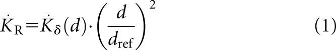 |
where  is the RAKR (SI unit: Gy s−1),
  is the air kerma rate measured at a distance d owing to photons of energy greater than δ and dref is the reference distance of 1 m. For typical HDR sources, it is more appropriate to express RAKR in mGy h−1 at 1 m or for LDR sources, in μGy h−1 at 1 m. The measurement distance needs to be large enough so that the source can be considered a point source.
The ICRU 72 also states that for elongated cylindrical sources, the reference point lies on the plane normal to and bisecting the long axis of the source.
The quantity RAKR has been widely adopted by all European countries, and it is also used in the Technical Document TECDOC-1274 report from the International Atomic Energy Agency (IAEA).13
Air kerma strength
In 1987, 2 years after the publication of ICRU report 38,9 the AAPM introduced the quantity air kerma strength for the specification of brachytherapy photon sources in the TG-32 report.14 Air kerma strength is extensively used in North America. The AAPM Task Group No. 43 adopted this quantity in the TG-43 report in 1995,15 and it is nowadays used worldwide as an input parameter for brachytherapy TPSs, which are generally based on the TG-43 dosimetry formalism. The TG-43 report was initially addressed to LDR interstitial brachytherapy seeds, but it has now been extended to all brachytherapy photon sources.2
Air kerma strength is defined as the product of the air kerma rate, , in free space (vacuum) at a measurement distance d from the source centre along the perpendicular bisector and the square of distance d. The recommended unit for air kerma strength is: 1 U = 1 μGy m−2 h−1 = 1 cGy cm2 h−1. In 2004, an update to the TG-43 report was published, TG-43U1,16 which contained a revised definition of air kerma strength. For the same reason as mentioned before, the contribution of the low-energy photons to the air kerma rate was excluded, by introducing a photon energy cut-off, δ, for defining air kerma strength:
where the air kerma strength, SK, is the product of the air kerma rate,  , at a distance d in vacuo and owing to photons of energy greater than δ, multiplied by the square of the measurement distance, d. The distance d must be large enough so that the source may be treated as a point source, and the measurement must be corrected for photon attenuation and scattering in air and scatter from any other objects and surfaces.
RAKR and air kerma strength are dimensionally different. They are related through the inverse square law to the reference distance, dref, as  . Provided that the multiples and submultiples of the units for
  and SK are consistent and the same energy cut-off, δ, is chosen, the numerical values of
  and SK are identical within the achievable dosimetric accuracy.
Absorbed dose rate to water
For the dosimetry of brachytherapy photon sources, the ultimate quantity of interest is the absorbed dose rate to water, which can either be calculated from the measured RAKR or air kerma strength, or it can be measured directly with an absorbed dose standard. The reference point (r0, θ0) in water is specified to lie on the perpendicular bisector of the source at a distance of 1 cm from the source centre, with r0 = 1 cm and θ0 = 90°.16 The dose rate to water  at the reference point is the only absolute dose rate required to define dosimetry parameters in the TG-43 formalism. At the reference point (r0, θ0), the general equation for the dose rate to water
  at an arbitrary point around a brachytherapy source reduces to:
for the quantity RAKR and to:
for the quantity air kerma strength. The dose rate constant Λ converts or SK to the dose rate to water. It is important to note that the unit for
  is the same in both expressions (Gy s−1 or a multiple of this unit). However, because of the different units for
  and SK, in Equation (3), Λ is a dimensionless constant, whereas in Equation (4), the unit for Λ is usually given as cGy h−1 U−1, which reduces to cm−2. The numerical value of Λ is identical in Equations (3) and (4) only if consistent units are used.
Until recently, the determination of Λ relied mainly on thermoluminescent dosemeter (TLD) measurements and Monte Carlo (MC) simulations. The average is taken to give the consensus value for Λ with a standard uncertainty of typically 4.8% (k = 1).16 This relative uncertainty of Λ dominates the overall relative uncertainty of the absorbed dose rate to water at 1-cm distance, if  is determined indirectly via air kerma rate measurements according to Equation (3) or (4). New absorbed dose standards for brachytherapy, which will be described in this review article, allow the experimental determination of Λ with a reduced uncertainty.
AIR KERMA RATE PRIMARY STANDARDS
As a result of the tight accuracy requirements for brachytherapy source calibrations, many national metrology institutes (NMIs) have developed dedicated primary standards for a range of brachytherapy sources over the past two decades. Generally, standards for the realization of air kerma rate are based on ionization chambers because of their relatively large signal-to-noise ratio.
Air kerma rate standards for low-dose-rate brachytherapy sources
The National Physical Laboratory (NPL; Teddington, UK) maintains a well-type ionization chamber as the secondary standard radionuclide calibrator17 for air kerma rate calibrations of LDR 125I seeds and LDR 192Ir wires and pins. The well chamber is traceably calibrated against the air kerma primary standard of the NPL.18,19 The primary air kerma measurement is performed at 1-m distance from the brachytherapy seeds using a spherical ionization chamber with a thin carbon fibre wall and a volume of approximately 3 l. The 3-l transfer chamber is calibrated in X-ray beams with average energies of 25 and 33 keV in order to derive the calibration coefficient for the 125I beam quality, which is taken as the average of both X-ray calibration coefficients. The 125I seed is rotated at 45° intervals about its long axis, and the mean of the eight measurements is calculated to average out any anisotropy of the source spectrum. The source is placed on a low scatter surface, and the measurement is made in air. Because of the large measurement distance of 1 m, no additional filter is needed to remove the 4.5-keV fluorescence X-rays, which are produced in the titanium encapsulation around the 125I source.
For LDR 192Ir measurements, the 3-l chamber is initially calibrated in X-ray beams with average energies ranging from 35 to 250 keV and also in 137Cs and 60Co γ-rays. The calibration coefficient for 192Ir is then determined by an appropriate weighting of the energy response of the chamber by the relative contribution to the air kerma from each line of the source energy spectrum.
The expanded uncertainty (k = 2) for an LDR 125I air kerma rate measurement is 5.6% and for LDR 192Ir is 1.5%.
The National Institute of Standards and Technology (NIST; Gaithersburg, MD) uses a wide-angle free air chamber (WAFAC)20,21 for the realization of air kerma strength for LDR 103Pd, 125I and 131Cs brachytherapy sources. The WAFAC is a cylindrical free air chamber with a large 8-cm diameter aperture, which is placed at a distance of 30 cm from the source. An aluminium filter of approximately 0.1-mm thickness is placed between the LDR source and the entrance aperture in order to remove the 4.5-keV fluorescence X-rays, which originate in the titanium encapsulation. The source is mounted vertically on a plastic holder and automatically rotated during measurement to average over any anisotropy in the transverse plane. The WAFAC contains two thin aluminized electrodes, which can be set to two different plate separations. The air kerma strength is determined from the difference in the ionization currents measured with the two collecting volumes.
At the University of Wisconsin Accredited Dosimetry Calibration Laboratory (UWADCL; Madison, WI), a variable-aperture free air chamber (VAFAC)22 is used for the measurement of LDR 103Pd, 125I and 131Cs sources. The VAFAC, with its variable-aperture stand, large diameter collecting electrode and special seed holder design, can be operated in an extrapolation mode. Other features are similar to the WAFAC, for instance the use of a thin aluminium filter between the source and the entrance aperture at 30-cm distance. Compared with the WAFAC of the NIST, which allows the measurement of photon energies of up to 40 keV, the VAFAC is suitable for measuring photon energies up to 70 keV and sources of up to 6-cm length. One of the main reasons for developing the VAFAC was the possibility of assessing the angular dependence of air kerma strength measurements.
A large-volume parallel-plate extrapolation chamber, called the Grossvolumen Extrapolationskammer (GROVEX),23 is the primary standard for the RAKR for LDR 103Pd and 125I photon sources at the Physikalisch-Technische Bundesanstalt (PTB; Braunschweig, Germany). The GROVEX is similar in its design to the WAFAC. However, the distance between the two parallel-plate electrodes can be adjusted from 0 to 20 cm to give several collecting volumes, rather than just two. The GROVEX method eliminates the wall effect of the thin graphite electrodes, and the extrapolation represents an ideal wall-less air chamber.
A comparison of LDR 103Pd and 125I seed calibrations with the WAFAC of NIST, the VAFAC of UWADCL and the GROVEX of PTB showed agreement of better than 1%, which was well within the stated uncertainties (k = 2) for the different ionization chambers, 1.6% for the WAFAC and VAFAC and 1.8% for the GROVEX.
The Laboratoire National Henri Becquerel (LNHB; Gif-sur-Yvette, France) has built a novel, circular free air chamber24 for the realization of the RAKR for LDR 103Pd and 125I photon sources. The chamber is in the shape of a torus with an outer diameter of about 1 m and a rectangular cross-section, which looks similar to a conventional free air chamber. The LDR seeds are placed at the geometric centre of the circular free air chamber inside a low-attenuating Kapton tube, which can be used with or without a tubular aluminium filter with approximately 0.1-mm radial thickness. The circular design of the chamber has two main advantages: it eliminates the need to rotate the source during the measurement to compensate for any anisotropy of the emergent spectrum in the transverse plane, and the accuracy of the source positioning is non-critical. The lead collimators are arranged such that the polar averaging angle is limited to ±1.6°. Sources with photon energies up to about 150 keV can be calibrated with the circular free air chamber of LNHB. The overall uncertainty for the RAKR has been estimated as 3% (k = 2). All standards discussed in this section are listed in Table 1.
Table 1.
Low-dose-rate air kerma rate standards
| Name of laboratory | Type of instrument | Study |
|---|---|---|
| National Physical Laboratory (Teddington, UK) | 3-l ionization chamber | Rossiter et al18 and Sephton et al19 |
| National Institute of Standards and Technology (Gaithersburg, MD) | Wide-angle free air chamber | Seltzer et al20 and Mitch and Soares21 |
| University of Wisconsin Accredited Dosimetry Calibration Laboratory (Madison, WI) | Variable-aperture free air chamber | Culberson et al22 |
| Physikalisch-Technische Bundesanstalt (Braunschweig, Germany) | Large-volume parallel-plate extrapolation chamber | Selbach et al23 |
| Laboratoire National Henri (Becquerel, Gif-sur-Yvette, France) | Circular free air chamber | Aubineau-Lanièce et al24 |
Air kerma rate standards for high-dose-rate brachytherapy sources
When no primary standard was available for the direct measurement of HDR 192Ir sources, the air kerma calibration coefficient for 192Ir dosemeters was determined using an indirect interpolation technique, which was originally developed by Goetsch et al25 at the UWADCL in 1991.
The effective energy of a typical encapsulated HDR 192Ir source (397 keV) lies approximately halfway between the effective energy of the NIST medium filtration 250-kVp X-ray beam (146 keV) and the mean energy of 137Cs (662 keV). Goetsch et al25 calibrated a therapy level cavity chamber (type: Exradin A3 with an air equivalent plastic wall) in air in these two reference beams and derived the 192Ir calibration coefficient of the ionization chamber by linear interpolation, with a correction for the differences in wall attenuation between X-ray, 137Cs and 192Ir irradiation. The ionization chamber was then used to measure the air kerma rate of an HDR 192Ir source at seven distances in air to determine the air kerma strength.
The calibration jig used for the Goetsch technique at the UWADCL was improved in 2002 and a detailed uncertainty analysis was performed.26 The total expanded uncertainty in the HDR source calibration in terms of air kerma strength was estimated to be 2.15% (k = 2). The Goetsch technique has been recommended by the IAEA.13
In 2006, Mainegra-Hing and Rogers27 showed that the interpolated calibration coefficient for 192Ir should be based on 1/NK values, not NK values. Mainegra-Hing and Rogers also argued that the wall correction factors would not be needed for the Goetsch interpolation method.
Other standards laboratories have implemented similar interpolation techniques. Büermann et al28 developed a method where the traceability to primary standards is maintained by calibrating a suitable ionization chamber in the reference fields for X-rays up to 300 kVp, 137Cs and 60Co γ-rays at the PTB. The PTB procedure comprises the evaluation of the entire calibration function of the ionization chamber between 30 keV and 60Co γ radiation, and interpolation for the 192Ir emission lines weighted with their emission probability. Until 2006, the measurements were carried out free in air, with a source-to-chamber distance of 1 m and a minimum distance of 2 m from the walls. The scatter contribution from the air and the walls was found to be approximately 5% of the total RAKR and was measured using a shadow shield method.29 The calibration set-up at PTB was recently improved by introducing a lead collimator, which has reduced the scatter contribution considerably.30 The relative uncertainty in the RAKR of an HDR 192Ir source measured with a 1000-cm3 LS01 chamber was found to be 2.4% (k = 2).
Piermattei and Azario31 used a similar interpolation technique, which is based on a measurement method developed by Verhaegen et al.29 Three spherical ionization chambers are initially calibrated against the air kerma primary standards for medium energy X-rays and 60Co γ-ray beams of the Italian National Institute of Ionizing Radiation Metrology (ENEA-INMRI; Casaccia, Italy). The RAKR of LDR and HDR 192Ir sources are measured with these calibrated chambers with an expanded uncertainty of 2.2% (k = 2).
Petersen et al32 describe a method for the derivation of 192Ir calibration coefficients for thimble-type ionization chambers (NE2561 and NE2571). The thimble chambers were calibrated against the [Van Swinden Laboratorium (VSL), formerly Nederlands Meetinstituut, Netherlands] primary standards for X-rays and 137Cs and 60Co γ-radiation. The calibration coefficients of the ionization chambers were obtained by weighting the chamber response according to the air kerma spectrum of the 192Ir source. In 2004, van Dijk et al33 used this interpolation method to derive an air kerma calibration coefficient for an NE2561 thimble chamber and presented an improved uncertainty budget. The chamber was then used in an in-air calibration jig to measure the RAKR of an HDR 192Ir source with an overall uncertainty of 1% (k = 2). For commercial 192Ir calibrations of thimble chambers, VSL states an overall uncertainty of 1.8% (k = 2).
In France, Douysset et al34 measure the RAKR of an HDR 192Ir source with an NE2571 thimble chamber with an interpolated calibration coefficient from measurements in 250-kV X-rays, 137Cs and 60Co radiation traceable to the LNHB air kerma standards. The RAKR measurement is made by rotating the thimble chamber around the 192Ir source on a precisely known radius over the range 0–225 mm with an accuracy of ±52 µm and by deriving the source-to-chamber distance from a graph showing the ionization current as a function of the measurement angle. The translation and rotation stages of the measurement set-up allow the measurement of the RAKR over a 360° angle in the transverse plane. The expanded uncertainty (k = 2) in the source calibration is 1.2%.
The traceability route for the interpolation methods described in this section is through external beam primary standards. All interpolation methods discussed in this section require an interpolation between the highest X-ray energy and the 137Cs or 60Co quality. Although the interpolation methods give reasonable results and measurement uncertainties, the determination of the energy response of the ionization chamber over the relevant energy range is a time-consuming and therefore costly process.32
The Radiological Standards Laboratory of the Bhabha Atomic Research Centre (Mumbai, India) used their LDR primary standard, a 60-cm3 spherical graphite ionization chamber, for the calibration of an HDR 192Ir source.35 The reported overall uncertainty in the RAKR measurement was 2% (k = 2), which is comparable with the uncertainties achievable with the interpolation methods described in this review.
In 1993, the British Institute of Radiology/Institute of Physical Sciences in Medicine brachytherapy working party36 in the UK recommended that the calibration coefficient of a thimble chamber for use with 192Ir should be that for the highest available kilovoltage quality at the NPL, that is, for heavily filtered 280-kVp therapy level X-rays. For thimble chamber calibrations in the 50 to 280-kV X-ray range, no build-up cap is required to establish electronic equilibrium. For the measurement of HDR 192Ir sources with a mean energy of approximately 400 keV, the chamber was set up in a calibration jig with a source-to-chamber distance of typically 10 cm and fitted with a build-up cap. The expanded uncertainty of the chamber calibration coefficient for the 280-kVp X-ray quality quoted by NPL is 1.2% (k = 2). Owing to the uncertainties in the extrapolation of the calibration curve to the effective energy of 192Ir (397 keV) and corrections, which had to be made for the effects of the build-up cap, the non-uniformity of the electron fluence across the thimble chamber and jig scatter, it was difficult to estimate the total uncertainty in the source calibration.
In 2004, the NPL commissioned a spherical graphite-walled cavity ionization chamber with a collecting volume of 102.52 cm3 as the UK primary standard for HDR 192Ir brachytherapy sources.37 For the RAKR measurement, the source is placed inside a lead housing with a conical collimator in the front wall. The centre-to-centre source-to-chamber distance is 1.433 m to ensure that the graphite sphere of the cavity chamber is fully covered by the primary beam. The direct primary method at NPL for the realization of RAKR for HDR 192Ir is based on Bragg–Gray and large cavity theory. Deviations from the ideal Bragg–Gray conditions are accounted for by applying a MC-calculated electron fluence perturbation correction factor.38 Further chamber correction factors, like the wall correction factor for photon scatter and attenuation in the chamber wall, were also calculated with MC methods37,39,40 for the 192Ir beam quality. The polarity, stem scatter and air attenuation and scatter correction factors were determined by experiment. The direct measurement of HDR 192Ir sources with the NPL primary standard has resulted in a reduced relative uncertainty in the RAKR compared with the interpolation techniques used at other standards laboratories. The uncertainty in the HDR 192Ir source calibration has been estimated as 0.7% (k = 2). The calibrated source can be used to calibrate suitable secondary standard ionization chambers, such as well-type ionization chambers.41 The HDR 192Ir primary standard of NPL has been compared against the HDR 192Ir air kerma standards of LNHB42 and the Australian Radiation Protection and Nuclear Safety Agency (Yallambie, VIC, Australia);43 both comparisons showed good agreement within the quoted uncertainties.
Another air kerma primary standard for HDR 192Ir sources, which will be similar to the primary standard of NPL, is currently being developed at the Institute of Nuclear Energy Research (Taiwan, Province of China).44
Some of the air kerma rate and absorbed dose rate measurement methods described in this review have attempted to take into account the anisotropy of the source by either rotating the source or the detector or by using a ring-shaped detector. Other methods measure from either one or two directions, and the quantity of interest is determined from the average of multiple source transfers. The effect of the source anisotropy is included in the uncertainty evaluation. Table 2 summarizes all standards discussed in this section.
Table 2.
High-dose-rate air kerma rate standards
| Name of laboratory | Type of instrument | Study |
|---|---|---|
| University of Wisconsin Accredited Dosimetry Calibration Laboratory (Madison, WI) | Cavity ionization chamber | Goetsch et al25 and Stump et al26 |
| Physikalisch-Technische Bundesanstalt (Braunschweig, Germany) | Cavity ionization chamber | Büermann et al28 and Selbach30 |
| The Italian National Institute of Ionizing Radiation Metrology (Casaccia, Italy) | Cavity ionization chamber | Piermattei and Azario31 |
| Van Swinden Laboratorium (Delft, Netherlands) | Thimble chamber | Petersen et al32 and van Dijk et al33 |
| Laboratoire National Henri Becquerel (Gif-sur-Yvette, France) | Thimble chamber | Douysset et al34 |
| The Radiological Standards Laboratory, Bhabha Atomic Research Centre (Mumbai, India) | Cavity ionization chamber | Rajan et al35 |
| National Physical Laboratory (Teddington, UK) | Cavity ionization chamber | Sander and Nutbrown37 |
| Australian Radiation Protection and Nuclear Safety Agency (Yallambie, VIC, Australia) | Thimble chamber | Butler et al43 |
| Institute of Nuclear Energy Research (Taiwan, Province of China) | Cavity ionization chamber | Lee et al44 |
ABSORBED DOSE RATE TO WATER PRIMARY STANDARDS
A direct absorbed dose to water calibration of brachytherapy sources potentially reduces the overall relative uncertainty in the quantity of interest, the absorbed dose rate to water at the reference point perpendicular to the source axis,  with r0 = 1 cm and θ0 = 90°. If secondary standard ionization chambers can be directly calibrated against an absorbed dose to water primary standard, this will eliminate the need for the dose rate constant Λ in the TG-43 formalism. In the general two-dimensional (2D) equation for the calculation of the dose rate to water
  ,11,16 the product SKΛ (or
  ) can be replaced with
  .
.
Only recently, absorbed dose standards for brachytherapy photon sources have been developed by PSDLs. In 2008, within the framework of the European Metrology Research Programme (EMRP), the joint research project T2.J06 “Increasing cancer treatment efficacy using three-dimensional (3D) brachytherapy” was launched with the aim of developing methods for the direct measurement of the quantity absorbed dose rate to water in brachytherapy dosimetry with an uncertainty on the dose delivered to the target volume <10% (k = 2).45 This implementing Metrology in the European Research Area project was jointly supported by the European Commission and the European Association of National Metrology Institutes. From July 2008 to June 2011, ten European metrology institutes participated in the EMRP T2.J06 joint research project. Four of the ten institutes developed a total of seven new absorbed dose standards, three standards for LDR 125I seeds and four standards for HDR 192Ir sources. The target relative measurement uncertainty on the dose rate to water at the reference point was 4% (k = 2).
Absorbed dose rate standards for low-dose-rate brachytherapy sources
All three absorbed dose standards for LDR 125I sources developed as part of the EMRP project were based on ionometric measurement methods because of their high sensitivity.
The PTB absorbed dose standard for low-energy (E < 40 keV) interstitial brachytherapy sources (LDR 125I and 103Pd) is a large-volume air-filled parallel-plate extrapolation chamber (GROVEX II).46 The entrance plate and the back plate are made of water-equivalent material (RW1) with thin graphite electrodes diffused onto the inside surface of both plates. The measurement depth within the water phantom is defined by the thickness of the entrance plate. The source is mounted inside a small RW1 cylinder on the tip of a rotating polymethyl methacrylate (PMMA) rod at a 30-cm distance from the graphite electrode on the entrance plate. For the determination of the absorbed dose rate to water, a new algorithm was developed, allowing the calculation of  by applying a MC-calculated conversion factor to the difference of the ionization charge collected at two different plate separations.47,48 The relative uncertainty on the absorbed dose rate to water at 1 cm for LDR 125I interstitial brachytherapy sources has been estimated as 2.6% (k = 2).49
The ENEA-INMRI absorbed dose standard for low-energy (E < 40 keV) LDR brachytherapy sources is a cylindrical large-angle variable-volume (LAVV-1) ionization chamber, embedded in a high-purity graphite phantom and operating under “wall-less air chamber” conditions.50 The extrapolation chamber has a front window made of graphite with a water-equivalent thickness of 1 cm and allows a water kerma rate determination in a graphite phantom from measurements of the increment of the ionization current per increment of air cavity volume. An LDR brachytherapy source is inserted into a PMMA holder and rotated around its axis to account for any radial anisotropy. Both the measurement method and the conversion method applied to the ENEA-INMRI absorbed dose standard are based on the formalism, which has been developed for the GROVEX II chamber of PTB.47 Several correction and conversion factors have been determined for the LAVV-1 chamber of ENEA either by experiment or with MC simulations. The expanded uncertainty on  for LDR 125I seeds is 5.2% (k = 2), and this is dominated by the uncertainty in the chamber measuring volume of 2% (k = 2). It is expected that further improvements can be made to the determination of the measuring volume, which should result in a reduction of the relative uncertainty on
  to around 4% (k = 2).
At LNHB, the circular free air chamber, which was originally designed for RAKR measurements of LDR brachytherapy sources, has been modified slightly to enable absorbed dose rate measurements of LDR 125I sources.24 Instead of holding the iodine seed in a low-attenuating Kapton holder, for the absorbed dose measurement, the source is placed inside a spherical water-equivalent phantom with 1-cm radius made of PMMA. The source and phantom assembly is positioned at the centre of the ring-shaped chamber, and the water kerma rate at the surface of the PMMA sphere is measured. The water kerma rate is converted to  by applying a MC-calculated conversion factor. The relative uncertainty for the LDR 125I absorbed dose rate standard of LNHB has been estimated to be 3.2% (k = 2). Table 3 lists all standards discussed in this section.
Table 3.
Low-dose-rate absorbed dose rate standards
| Name of laboratory | Type of instrument | Study |
|---|---|---|
| Physikalisch-Technische Bundesanstalt (Braunschweig, Germany) | Large-volume parallel-plate extrapolation chamber | Schneider and Selbach46 and Schneider49 |
| The Italian National Institute of Ionizing Radiation Metrology (Casaccia, Italy) | Large-angle variable-volume ionization chamber | Toni et al50 |
| Laboratoire National Henri Becquerel (Gif-sur-Yvette, France) | Circular free air chamber | Aubineau-Lanièce et al24 |
Absorbed dose rate standards for high-dose-rate brachytherapy sources
The absorbed dose standards developed for measuring HDR brachytherapy γ-sources and described in this section are all based on calorimetry. This direct method is suitable for HDR sources because the high dose rate leads to a sufficient signal-to-noise ratio. Calorimetry is recognized as the best approach for establishing absorbed dose standards for use in reference dosimetry.51 Absorbed dose calorimetry is based on the assumption that all (or a known fraction) of the absorbed radiation energy appears as heat, so that the measurement of absorbed dose reduces to a measurement of a temperature change. A calorimetric determination of the dose at a point requires that a thermally isolated element has been arranged so that no significant heat transfer occurs during the irradiation and that corrections for radiation-induced chemical reactions are kept as small as possible. For brachytherapy applications, a small detector size is important in order to reduce the volume averaging effect because the dose distribution close to the source varies considerably owing to steep dose gradients.
In principle, water calorimetry allows the most direct realization of the quantity absorbed dose to water in a water phantom.52 Water is the standard reference material for clinical dosimetry because the absorption properties for ionizing radiation are similar to those of biological tissue.
Since the 1980s, water calorimeters have been developed and are now in use at many standards laboratories. Water has a low thermal diffusivity and can be used for measuring absorbed dose at a point. Domen53 built the first open tank water calorimeter and later improved the design by introducing a small sealed glass vessel filled with high-purity water, which was inserted in a large water tank,54 to control the heat defect. A heat defect exists when energy is absorbed or produced in induced radiochemical reactions or if the lattice energy of solid media is changed. Klassen and Ross55 showed that radiation-induced chemical reactions are the main cause for the heat defect of water. When establishing an absorbed dose standard as a primary standard, the heat defect, which can be of the order of a few percent, must be known.56
The major absorber materials used for calorimetry in radiation dosimetry have traditionally been tissue equivalent plastics or graphite.57 Nowadays, the predominant materials used in radiometric calorimeters are water and graphite. Graphite has a low atomic number, it is a solid that can be easily machined, and it has similar energy attenuation and absorption properties compared with water. For this reason, the ICRU initially recommended the use of graphite as the absorbing medium in the calorimetric realization of absorbed dose to water.58 In a graphite calorimeter, the core is held at constant temperature by placing it inside a jacket and a shield of the same material, which in turn are placed in a large graphite phantom. The components are typically separated by an evacuated gap, removing conduction and convection between components.
An advantage of graphite calorimeters is that the heat defect is generally assumed to be negligible.56 The main concern is the level of dissolved oxygen in graphite. However, if the graphite calorimeter is operated under vacuum, no atmospheric oxygen will be present and no radiation-induced chemical reactions can contribute to a heat defect. Any heat defect owing to radiation-induced changes of the lattice structure of polycrystalline graphite is generally assumed to be negligible for the energies transferred by low- and high-energy photon beams used for radiotherapy.
For the past two decades, there has been a general trend to move reference dosimetry for radiotherapy towards absorbed dose to water standards. PSDLs have developed absorbed dose standards for 60Co teletherapy sources, and for external high-energy photon and electron beams.52 The existing calorimeters were originally designed for measuring external radiation fields, which produce linear temperature gradients inside the calorimeter owing to the large source-to-detector distance. However, measuring in the steep dose gradients close to brachytherapy sources required a modified design.
At the end of 2007, shortly after the beginning of the EMRP T2.J06 project, Sarfehnia et al59 (McGill University, Montréal, Canada) published a feasibility study of direct absorbed dose measurements for HDR 192Ir sources using a modified version of the McGill Domen-type water calorimeter. A special acrylic holder was designed for holding several nylon catheters close to the parallel-plate calorimeter vessel inside a water phantom. The HDR 192Ir source was inserted into the catheters at five different source-to-detector separations. The aim of the feasibility study was to investigate how the expected steep temperature gradient owing to the source self-heating in addition to the large dose gradient close to the source would influence the measurement of absorbed dose in water. Positioning uncertainties and source self-heating effects increase with decreasing distance between the source and the measurement point, but the measurement signal decreases with increasing distance from the source. Sarfehnia et al concluded that an absolute dose measurement of HDR 192Ir sources with an uncertainty <5% (k = 2) would be achievable, provided that (a) uncertainties in the source positioning can be reduced to <0.3 mm, (b) the measurement point is located on the perpendicular bisector of the source in the range 2.5–5 cm and (c) a minimum dose of 1 Gy is delivered. In 2010, Sarfehnia and Seuntjens60 presented an improved version of the calorimeter, the McGill portable water calorimeter, taking into account the results of the previous feasibility study and by using active cooling of the water calorimeter to 4 °C. At this temperature, water has its maximum density, and setting the operating temperature to this value minimizes convection.61 Perturbation correction factors were calculated with MC techniques and heat transfer simulations. A detailed uncertainty budget was presented for absorbed dose rate measurements of an HDR 192Ir source for a source-to-detector distance of 5.5 cm. The relative uncertainty in the absorbed dose was estimated as 3.8% (k = 2).60
PTB, VSL, NPL and ENEA-INMRI developed four independent designs of absorbed dose standards for HDR 192Ir sources as part of the EMRP project.
PTB has modified one of its existing water calorimeters for the measurement of absorbed dose rate to water close to 192Ir and 60Co HDR brachytherapy sources.62 The design of the calorimeter is essentially the same as the primary standard water calorimeter of PTB for 60Co external radiation beams.63 A source holder has been built to ensure accurate positioning of the HDR source in front of the parallel-plate calorimetric detector. A stainless steel needle is attached to the PMMA holder and connected to the afterloader. The HDR source is moved into the steel tube, which, in turn, is placed inside the water calorimeter. Measurements of the absorbed dose are possible at four different source-to-detector distances from 24.5 to 60 mm. The calorimetric measurements at these four distances are then extrapolated to the reference distance of 1 cm. The calorimeter is operated at 4 °C, and between calorimeter runs, the source is kept in a temperature-controlled lead block, also at 4 °C, to ensure that the source temperature remains at the operating temperature of the calorimeter and to minimize the self-heating effect on the absorbed dose measurements. The PTB water calorimeter is capable of measuring the absorbed dose rate to water for HDR 192Ir sources with an expanded uncertainty of 3.48% (k = 2).
At VSL, the HDR 192Ir absorbed dose standard64 is based on the design of the existing water calorimeter for external 60Co and clinical linac beams and operated at 4 °C. The main modification made was a newly designed high-purity cell. The thermostat, the phantom and the water cooling unit remained the same. The HDR 192Ir source is inserted through an aluminium heat sink to the centre of the detector. The heat sink has been included to reduce contribution of the self-heating effect to the temperature increase at the point of measurement where only the distributed radiation heating should be considered. Four thermistors, which measure the temperature rise at 20-mm distance from the source centre, are evenly distributed in the transverse plane around the HDR source. This configuration makes the calorimeter less sensitive to source positioning errors. Test measurements with an HDR 192Ir source were performed at the end of the EMRP T2.J06 project in 2011,45 which showed noise on the measured signal of around 6% [Jacco de Pooter Van Swinden Laboratorium, Delft, Netherlands, 2011, personal communication]. Further modifications are required to the VSL calorimeter before the quantity  can be determined reliably.
The absorbed dose standard of NPL for HDR 192Ir is a novel cylindrical graphite calorimeter.65 MC and heat transfer simulations were made to optimize the dimensions of the main calorimeter components. The calorimeter measures the quantity absorbed dose rate to graphite in a ring-shaped core at 25-mm radial distance from the centre of the HDR source in the transverse plane. MC-calculated perturbation correction factors are applied to yield the absorbed dose rate in a homogeneous graphite phantom. The measured quantity is then converted to  by applying a MC-calculated graphite-to-water conversion factor. The calorimeter is made of five graphite pieces. The ring-shaped core (25 mm radius, 5 mm height and 2 mm radial thickness) is surrounded by a 1-mm vacuum gap. Two graphite tubes between the HDR 192Ir source and the core are separated by a 0.25-mm vacuum gap to minimize conductive heat transfer from the source to the core. The graphite tubes and the core are embedded in two large graphite rings with an outside radius of 10 cm and a height of 14 cm. For the absorbed dose rate measurement, the HDR 192Ir source is inserted through an aluminium tube to the centre of the cylindrical graphite phantom opposite the ring-shaped core. The absorbed dose rate measurements of HDR 192Ir sources in terms of
  can be made with the graphite calorimeter of NPL in two different operating modes, either by measuring the temperature increase in the core owing to the energy imparted by ionizing radiation (quasi-adiabatic mode) with a relative uncertainty of 2.0% (k = 2) or by actively keeping all graphite pieces at a constant temperature and by measuring the change in the electrical heating power before and during irradiation (quasi-isothermal mode) with a relative uncertainty of 1.4% (k = 2).
The HDR 192Ir absorbed dose standard developed at ENEA-INMRI is also a graphite calorimeter.66 The design has been optimized on the basis of MC and heat transfer simulations. The graphite calorimeter consists of three annular graphite bodies with cylindrical symmetry around the source axis. The nominal dimensions of the ring-shaped core are identical to those in the NPL calorimeter. However, in the ENEA-INMRI calorimeter, the core is completely surrounded by a 0.5-mm thick graphite jacket, and both components are separated from each other by a 0.75-mm vacuum gap. The jacket is surrounded by another 0.75-mm vacuum gap and, finally, by a graphite block, which is mounted inside a vacuum housing. This assembly can be inserted in a larger graphite phantom to provide full backscatter conditions at the measurement point in the core. The absorbed dose standard of ENEA for HDR 192Ir was operated in the quasi-adiabatic mode and the relative uncertainty on  was estimated to be 2.8% (k = 2). Table 4 summarizes all five standards mentioned in this section.
Table 4.
High-dose-rate absorbed dose rate standards
| Name of laboratory | Type of instrument | Study |
|---|---|---|
| McGill University (Montréal, Canada) | Water calorimeter | Sarfehnia et al59 and Sarfehnia and Seuntjens60 |
| Physikalisch-Technische Bundesanstalt (Braunschweig, Germany) | Water calorimeter | Bambynek and Krauss62 |
| Van Swinden Laboratorium (Delft, Netherlands) | Water calorimeter | De Prez and De Pooter64 |
| National Physical Laboratory (Teddington, UK) | Graphite calorimeter | Sander et al65 |
| The Italian National Institute of Ionizing Radiation Metrology (Casaccia, Italy) | Graphite calorimeter | Guerra et al66 |
OTHER DOSIMETRY TECHNIQUES FOR BRACHYTHERAPY
Fricke dosimetry
A third method for the determination of absorbed dose to a medium, in addition to the ionometric and calorimetric methods, which have already been discussed in this review, is the chemical method (Fricke dosimetry). Austerlitz et al67 developed a ring-shaped ferrous sulphate Fricke device for the absolute measurement of the dose to water of an HDR 192Ir source at the reference point, D(r0, θ0). The source was inserted into a PMMA rod and then located at the centre of a ring-shaped cavity with 1.5-mm thickness, 5-mm height and 10-mm radius. The cavity was filled with Fricke solution. The whole assembly was then immersed in a water phantom during irradiations. The overall uncertainty in the direct measurement of D(r0, θ0) was estimated to be 6.86% (k = 2).
Relative dosimetry for dose mapping
Various other experimental dosimetry techniques have been developed for 2D and 3D dose mapping around brachytherapy photon sources, for instance TLDs,68 chemical (alanine/EPR) dosemeters,69 silicon diodes,70 diamond detectors,71 plastic scintillators,72 radiochromic film,73 polymer gel dosimetry,74 miniature ionization chambers75 and liquid-filled ionization chambers.76 Although the dosemeters mentioned in this section provide adequate spatial resolution for the measurement of the absorbed dose at a point close to brachytherapy sources, all dosemeters require a calibration in a known radiation field, and they are subject to volume averaging, energy dependence, directional anisotropy, self-attenuation and long-term stability effects. Depending on the type of detector and the measurement distance from the source centre, the relative measurement uncertainty ranges from around 6% to 20% (k = 2). Further high-resolution relative dosimetry methods for the accurate determination of 3D dose distributions close to brachytherapy sources77–79 were developed within the EMRP T2.J06 project and compared with MC calculations.80
Monte Carlo dosimetry
MC simulation is nowadays a widely used and accepted dosimetry tool.15,16 The MC method is a statistical simulation of radiation processes, e.g. the emission of photons, their interactions with matter and the transport and slowing down of charged particles (e.g. electrons) in different media. Recent increases in computer processor speed have led to a rapid increase in the use of MC methods in medical physics since the 1990s.81 TG-43 dosimetric parameters for various commercially available brachytherapy sources have been calculated using MC techniques and consensus data sets are published in peer-reviewed journals, based on both TLD-measured and MC-calculated dose distributions near brachytherapy sources.16 A summary of the recommended and consensus TG-43 data sets was compiled by the brachytherapy physics quality system (BRAPHYQS) subgroup of ESTRO and is available online from the University of Valencia; Valencia, Spain, at www.uv.es/braphyqs.
A variety of MC code systems are available to simulate the transport of different particle types through matter, for example, the electron gamma shower code EGS/EGSnrc,82 PENELOPE,83 MCNP,84 PTRAN,85 GEANT486 and MCNPX.87 In the TG-43U1 report,16 the AAPM examined the role of MC codes for simulating brachytherapy source dose distributions. Only EGS/EGSnrc,82 MCNP84 and the PTRAN code85 were mentioned in the TG-43U1 report as examples of well-benchmarked codes for use in brachytherapy.
In radiotherapy physics, EGSnrc remains the most widely used MC code.88 The Carleton Laboratory for Radiotherapy Physics database of TG-43 brachytherapy dosimetry parameters, which was launched in 2008, contains EGSnrc-calculated dosimetry parameters of various brachytherapy sources.89
DISCUSSION AND OUTLOOK
Over the past two decades, reference dosimetry for brachytherapy sources has improved considerably and many new air kerma and absorbed dose standards for LDR and HDR brachytherapy sources have been developed by several national standards laboratories worldwide. A huge variety of different independent standards for reference dosimetry in brachytherapy are now available. The recent development of dedicated absorbed dose rate standards for brachytherapy within the framework of the EMRP has reduced the overall relative uncertainty for source calibrations in terms of absorbed dose rate to water at a distance of 1 cm from the source, , considerably, ranging from 5.4% to 1.4% (k = 2). The new absorbed dose standards, together with the existing air kerma standards at the NMIs, which participated in the EMRP T2.J06 project, allowed an experimental determination of the dose rate constant Λ for different LDR 125I and HDR 192Ir sources as the ratio
  with a significant decrease in the associated relative uncertainty to <5% (k = 2).90,91 As a consequence of the reduced measurement uncertainty, medical physicists will be able to characterize brachytherapy sources more accurately with traceably calibrated secondary standards, such as well-type ionization chambers, and this will potentially improve the brachytherapy treatment outcome.
Several comparisons of brachytherapy standards have already been completed,34,42,43,90,92 and generally good agreement was found between the different measurement techniques and methods. The brachytherapy standards working group at the Bureau International des Poids et Mesures (BIPM) in Sèvres, France, has set up an ongoing key comparison for HDR 192Ir air kerma rate primary standards. Similar international comparisons should be organized by the BIPM for 125LDR air kerma standards and the new absorbed dose standards for brachytherapy. This will lead to a robust link between the different standards worldwide.
New standards for brachytherapy with miniature X-ray sources (electronic brachytherapy) are currently being developed at NIST and UWADCL. Since mid-2012, PTB and the Czech Metrology Institute, Prague, Czech Republic, have been involved in one of the tasks of a new 3-year EMRP joint research project “Metrology for radiotherapy using complex radiation fields” to characterize two electronic brachytherapy sources and to develop a suitable absorbed dose standard.93
The future challenge for the standards laboratories will be to keep up with the continued development of new types of brachytherapy sources, for instance electronic brachytherapy sources or different radionuclides, which will require NMIs to build or modify suitable primary standards in order to allow traceable brachytherapy source calibrations in the future.
Following the successful implementation of new absorbed dose standards, the participants of the EMRP T2.J06 project promote the development of an updated international protocol for reference dosimetry of brachytherapy sources based on absorbed dose to water standards.94 Moving from air kerma to absorbed dose to water for brachytherapy would be analogous to the implementation of absorbed dose to water dosimetry for external beam radiotherapy as promoted in the IAEA TRS-398 code of practice.95 Reich96 argued in favour of the quantity absorbed dose to water for radiotherapy field instruments in general. Now that the feasibility of absorbed dose standards has been demonstrated, it would be a good time implementing this proposal for brachytherapy. Only a thorough comparison of the air kerma rate and absorbed dose rate to water methods will show which of the two calibration routes will be more robust against future re-evaluations of key data97 in reference dosimetry for brachytherapy.
The transition from air kerma to absorbed dose calibrations for brachytherapy would require a future update of the AAPM TG-43 formalism and minor changes to the treatment planning software. However, the hospitals could still use the same type of secondary standards, which are currently in use. For consistency, this transition process should be applied across the entire field of brachytherapy.98 For the end user, any change of the current air-kerma-based formalism should result in at least the same, but ideally, lower source calibration uncertainties. This will require an international collaboration, not only between the PSDLs and end users but also between AAPM, ESTRO and ICRU, who should define consistent quantities and units for brachytherapy dosimetry. The current situation, where two different quantities for the source characterization in terms of air kerma rate are used, the RAKR and air kerma strength, respectively, can be confusing and should be avoided. The eventual move to absorbed dose calibrations for all brachytherapy sources would eliminate the need for unit conversions from RAKR to air kerma strength and vice versa and reduce the possibility of dose calculation errors and interchangeable use of the two quantities.
REFERENCES
- 1.Nath R, Anderson LL, Meli JA, Olch AJ, Stitt JA, Williamson JF. Code of practice for brachytherapy physics: report of the AAPM Radiation Therapy Committee Task Group No. 56. American Association of Physicists in Medicine. Med Phys 1997; 24: 1557–98. [DOI] [PubMed] [Google Scholar]
- 2.Venselaar JLM, Pérez-Calatayud J, eds. A practical guide to quality control of brachytherapy equipment. ESTRO booklet no. 8. Brussels, Belgium: ESTRO; 2004. [Google Scholar]
- 3.Kutcher GJ, Coia L, Gillin M, Hanson WF, Leibel S, Morton RJ, et al. Comprehensive QA for radiation oncology: report of AAPM Radiation Therapy Committee Task Group 40. Med Phys 1994; 21: 581–618. [DOI] [PubMed] [Google Scholar]
- 4.DeWerd LA, Ibbott GS, Meigooni AS, Mitch MG, Rivard MJ, Stump KE, et al. A dosimetric uncertainty analysis for photon-emitting brachytherapy sources: report of AAPM Task Group No. 138 and GEC-ESTRO. Med Phys 2011; 38: 782–801. [DOI] [PMC free article] [PubMed] [Google Scholar]
- 5.Bjerke H, DeWerd LA, Seuntjens JP, Bidmead M. Source calibration. In: Venselaar JLM, Baltas D, Meigooni AS, Hoskin PJ, eds. Comprehensive brachytherapy: physical and clinical aspects. Boca Raton, FL: CRC Press; 2013. pp. 61–74. [Google Scholar]
- 6.International Atomic Energy Agency. Calibration of dosimeters used in radiotherapy. Technical Reports Series No. 374. Vienna, Austria: IAEA, 1994. [Google Scholar]
- 7.International Electrotechnical Commission. Medical electrical equipment—dosimetric instruments as used in brachytherapy—part 1: instruments based on well-type ionization chambers. IEC 62467–1 Ed. 1.0. Geneva, Switzerland: IEC; 2009.
- 8.Soares CG, Douysset G, Mitch MG. Primary standards and dosimetry protocols for brachytherapy sources. Metrologia 2009; 46: S80–98. [Google Scholar]
- 9.International Commission on Radiation Units and Measurements. Dose and volume specification for reporting intracavitary therapy in gynecology. ICRU report 38. Bethesda, MD: ICRU; 1985. [Google Scholar]
- 10.International Commission on Radiation Units and Measurements. Dose and volume specification for reporting interstitial therapy. ICRU report 58. Bethesda, MD: ICRU, 1997. [Google Scholar]
- 11.International Commission on Radiation Units and Measurements. Dosimetry of beta rays and low-energy photons for brachytherapy with sealed sources. ICRU report 72. Bethesda, MD: ICRU, 2004. [Google Scholar]
- 12.Perez-Calatayud J, Ballester F, Das RK, DeWerd LA, Ibbott GS, Meigooni AS, et al. Dose calculation for photon-emitting brachytherapy sources with average energy higher than 50 keV: report of the AAPM and ESTRO. Med Phys 2012; 39: 2904–29. [DOI] [PubMed] [Google Scholar]
- 13.International Atomic Energy Agency. Calibration of photon and beta ray sources used in brachytherapy. IAEA-TECDOC-1274. Vienna, Austria: IAEA; 2002.
- 14.American Association of Physicists in Medicine. Report of AAPM task group 32: specification of brachytherapy source strength. AAPM Report No. 21. New York, NY: American Institute of Physics; 1987. [Google Scholar]
- 15.Nath R, Anderson LL, Luxton G, Weaver KA, Williamson JF, Meigooni AS. Dosimetry of interstitial brachytherapy sources: recommendations of the AAPM Radiation Therapy Committee Task Group No. 43. American Association of Physicists in Medicine. Med Phys 1995; 22: 209–34. [DOI] [PubMed] [Google Scholar]
- 16.Rivard MJ, Coursey BM, DeWerd LA, Hanson WF, Huq MS, Ibbott GS, et al. Update of AAPM Task Group No. 43 Report: a revised AAPM protocol for brachytherapy dose calculations. Med Phys 2004; 31: 633–74. [DOI] [PubMed] [Google Scholar]
- 17.Baker M, Bass GA, Woods MJ. Calibration of the NPL secondary standard radionuclide calibrator for 125I seeds used for prostate brachytherapy. National Physical Laboratory. Appl Radiat Isot 2002; 56: 321–5. [DOI] [PubMed] [Google Scholar]
- 18.Rossiter MJ, Williams TT, Bass GA. Air kerma rate calibration of small sources of 60Co, 137Cs, 226Ra and 192Ir. Phys Med Biol 1991; 36: 279–84. [Google Scholar]
- 19.Sephton JP, Woods MJ, Rossiter MJ, Williams TT, Dean JCJ, Bass GA, et al. Calibration of the NPL secondary standard radionuclide calibrator for 192Ir brachytherapy sources. Phys Med Biol 1993; 38: 1157–64. [DOI] [PubMed] [Google Scholar]
- 20.Seltzer SM, Lamperti PJ, Loevinger R, Mitch MG, Weaver JT, Coursey BM. New national air-kerma-strength standards for 125I and 103Pd brachytherapy seeds. J Res Natl Inst Stand Technol 2003; 108: 337–58. [DOI] [PMC free article] [PubMed] [Google Scholar]
- 21.Mitch MG, Soares CG. Primary standards for brachytherapy sources. In: Rogers DWO, Cygler JE, eds. Clinical dosimetry for radiotherapy. Madison, WI: Medical Physics Publishing; 2009. pp 549–65. [Google Scholar]
- 22.Culberson WS, DeWerd LA, Anderson DR, Micka JA. Large-volume ionization chamber with variable apertures for air-kerma measurements of low-energy radiation sources. Rev Sci Instrum 2006; 77: 015105. [Google Scholar]
- 23.Selbach H-J, Kramer H-M, Culberson WS. Realization of reference air-kerma rate for low-energy photon sources. Metrologia 2008; 45: 422–8. [Google Scholar]
- 24.Aubineau-Lanièce I, Chauvenet B, Cutarella D, Gouriou J, Plagnard J, Aviles Lucas P. LNE-LNHB air-kerma and absorbed dose to water primary standards for low dose-rate 125I brachytherapy sources. Metrologia 2012; 49: S189–92. [Google Scholar]
- 25.Goetsch SJ, Attix FH, Pearson DW, Thomadsen BR. Calibration of 192Ir high-dose-rate afterloading systems. Med Phys 1991; 18: 462–7. [DOI] [PubMed] [Google Scholar]
- 26.Stump KE, DeWerd LA, Micka JA, Anderson DR. Calibration of new high dose rate 192Ir sources. Med Phys 2002; 29: 1483–8. [DOI] [PubMed] [Google Scholar]
- 27.Mainegra-Hing E, Rogers DWO. On the accuracy of techniques for obtaining the calibration coefficient NK of 192Ir HDR brachytherapy sources. Med Phys 2006; 33: 3340–7. [DOI] [PubMed] [Google Scholar]
- 28.Büermann L, Kramer H-M, Schrader H, Selbach H-J. Activity determination of 192Ir solid sources by ionization chamber measurements using calculated corrections of self-absorption. Nucl Instr Meth Phys Res A 1994; 339: 369–76. [Google Scholar]
- 29.Verhaegen F, van Dijk E, Thierens H, Aalbers A, Seuntjens J. Calibration of low activity 192Ir brachytherapy sources in terms of reference air kerma rate with large volume spherical ionization chambers. Phys Med Biol 1992; 37: 2071–82. [Google Scholar]
- 30.Selbach H-J. New calibration device for 192Ir and 60Co-brachytherapy radiation sources [In German]. In: Bogner L, Dobler B, ed. Medizinische Physik 2006. Tagungsband der 37. Jahrestagung der Deutschen Gesellschaft für Medizinische Physik e.V.; 20–23 September 2006; Regensburg, Germany. Regensburg, Germany: Deutsche Gesellschaft für Medizinische Physik, 2006.
- 31.Piermattei A, Azario L. Applications of the Italian protocol for the calibration of brachytherapy sources. Phys Med Biol 1997; 42: 1661–9. [DOI] [PubMed] [Google Scholar]
- 32.Petersen JJ, van Dijk E, Aalbers AHL. Comparison of methods for derivation of 192Ir calibration factors for the NE 2561 & 2571 ionisation chambers. Report S-El-94.01. Utrecht, The Netherlands: NMi Van Swinden Laboratorium; 1994.
- 33.van Dijk E, Kolkman-Deurloo I-K, Damen PMG. Determination of the reference air kerma rate for 192Ir brachytherapy sources and the related uncertainty. Med Phys 2004; 31: 2826–33. [DOI] [PubMed] [Google Scholar]
- 34.Douysset G, Gouriou J, Delaunay F, DeWerd L, Stump K, Micka J. Comparison of dosimetric standards of USA and France for HDR brachytherapy. Phys Med Biol 2005; 50: 1961–78. doi: 10.1088/0031-9155/50/9/003 [DOI] [PubMed] [Google Scholar]
- 35.Rajan KNG, Selvam TP, Bhatt BC, Vijayam M, Patki VS, Vinatha, et al. Direct calibration of a reference standard against the air kerma strength primary standard, at 192Ir HDR energy. Phys Med Biol 2002; 47: 1047–58. [DOI] [PubMed] [Google Scholar]
- 36.Aird EGA, Jones CH, Joslin CAF, Klevenhagen SC, Rossiter MJ, Welsh AD, et al. Recommendations for brachytherapy dosimetry. Report of a joint working party of the BIR and IPSM. London, UK: British Institute of Radiology; 1993. [Google Scholar]
- 37.Sander T, Nutbrown RF. The NPL air kerma primary standard TH100C for high dose rate 192Ir brachytherapy sources. NPL report RD004. Teddington, UK: National Physical Laboratory; 2006. [Google Scholar]
- 38.Bielajew AF. Ionisation cavity theory: a formal derivation of perturbation factors for thick-walled ion chambers in photon beams. Phys Med Biol 1986; 31: 161–70. [Google Scholar]
- 39.Bielajew AF. An analytic theory of the point-source non-uniformity correction factor for thick-walled ionisation chambers in photon beams. Phys Med Biol 1990; 35: 517–38. [Google Scholar]
- 40.Borg J, Kawrakow I, Rogers DWO, Seuntjens JP. Monte Carlo study of correction factors for Spencer-Attix cavity theory at photon energies at or above 100 keV. Med Phys 2000; 27: 1804–13. [DOI] [PubMed] [Google Scholar]
- 41.Bidmead AM, Sander T, Locks SM, Lee CD, Aird EGA, Nutbrown RF, et al. The IPEM code of practice for determination of the reference air kerma rate for HDR 192Ir brachytherapy sources based on the NPL air kerma standard. Phys Med Biol 2010; 55: 3145–59. [DOI] [PubMed] [Google Scholar]
- 42.Douysset G, Sander T, Gouriou J, Nutbrown R. Comparison of air kerma standards of LNE-LNHB and NPL for 192Ir HDR brachytherapy sources: EUROMET project no 814. Phys Med Biol 2008; 53: N85–97. [DOI] [PubMed] [Google Scholar]
- 43.Butler D, Haworth A, Sander T, Todd S. Comparison of 192Ir air kerma calibration coefficients derived at ARPANSA using the interpolation method and at the National Physical Laboratory using a direct measurement. Australas Phys Eng Sci Med 2008; 31: 332–8. [DOI] [PubMed] [Google Scholar]
- 44.Lee JH, Wang JN, Huang TT, Su SH, Chang BJ, Su CH, et al. Evaluation of wall correction factor of INER’s air-kerma primary standard chamber and dose variation by source displacement for HDR 192Ir brachytherapy. Biomed Res Int 2013; 2013: 436979. [DOI] [PMC free article] [PubMed] [Google Scholar]
- 45.Toni MP. Publishable JRP summary for project T2.J06 (JRP Brachytherapy). Inceasing cancer treatment efficacy using 3D brachytherapy. 2010. Available from: http://www.euramet.org/fileadmin/docs/EMRP/JRP/iMERA-plus_JRPs_2010-06-22/T2.J06.pdf [Google Scholar]
- 46.Schneider T, Selbach H-J. Realization of the absorbed-dose to water for I-125 interstitial brachytherapy sources. Radiother Oncol 2011; 100: 442–5. [DOI] [PubMed] [Google Scholar]
- 47.Schneider T. A method to determine the water kerma in a phantom for x-rays with energies up to 40 keV. Metrologia 2009; 46: 95–100. [Google Scholar]
- 48.Schneider T. A robust method for determining the absorbed dose to water in a phantom for low-energy photon radiation. Phys Med Biol 2011; 56: 3387–402. [DOI] [PubMed] [Google Scholar]
- 49.Schneider T. The PTB primary standard for the absorbed-dose to water for I-125 interstitial brachytherapy sources. Metrologia 2012; 49: S198–202. [Google Scholar]
- 50.Toni MP, Pimpinella M, Pinto M, Quini M, Cappadozzi G, Silvestri C, et al. Direct determination of the absorbed dose to water from 125I low dose-rate brachytherapy seeds using the new absorbed dose primary standard developed at ENEA-INMRI. Metrologia 2012; 49: S193–7. [Google Scholar]
- 51.Ross CK, Klassen NV. Water calorimetry for radiation dosimetry. Phys Med Biol 1996; 41: 1–29. [DOI] [PubMed] [Google Scholar]
- 52.Seuntjens J, Duane S. Photon absorbed dose standards. Metrologia 2009; 46: S39–58. [Google Scholar]
- 53.Domen SR. Absorbed dose water calorimeter. Med Phys 1980; 7: 157–9. [DOI] [PubMed] [Google Scholar]
- 54.Domen SR. A sealed water calorimeter for measuring absorbed dose. J Res Natl Inst Stand Technol 1994; 99: 121–41. [DOI] [PMC free article] [PubMed] [Google Scholar]
- 55.Klassen NV, Ross CK. Water calorimetry: the heat defect. J Res Natl Inst Stand Technol 1997; 102: 63–74. [DOI] [PMC free article] [PubMed] [Google Scholar]
- 56.International Commission on Radiation Units and Measurements. Dosimetry of high-energy photon beams based on standards of absorbed dose to water. ICRU report 64. Bethesda, MD: ICRU; 2001. [Google Scholar]
- 57.Seuntjens JP, Du Sautoy AR. Review of calorimeter based absorbed dose to water standards. Standards and codes of practice in medical radiation dosimetry. Proc Int Symp Vienna, 2002; IAEA-CN-96–3. Vienna, Austria: IAEA, 2003.
- 58.International Commission on Radiation Units and Measurements. Radiation dosimetry: x-rays and gamma rays with maximum energies between 0.6 MeV and 50 MeV. ICRU report 14. Washington, DC: ICRU; 1969. [Google Scholar]
- 59.Sarfehnia A, Stewart K, Seuntjens J. An absorbed dose to water standard for HDR 192Ir brachytherapy sources based on water calorimetry: numerical and experimental proof-of-principle. Med Phys 2007; 34: 4957–61. [DOI] [PubMed] [Google Scholar]
- 60.Sarfehnia A, Seuntjens J. Development of a water calorimetry-based standard for absorbed dose to water in HDR 192Ir brachytherapy. Med Phys 2010; 37: 1914–23. [DOI] [PubMed] [Google Scholar]
- 61.Seuntjens J, Palmans H. Correction factors and performance of a 4 degrees C sealed water calorimeter. Phys Med Biol 1999; 44: 627–46. [DOI] [PubMed] [Google Scholar]
- 62.Bambynek M, Krauss A. Determination of absorbed dose to water for 192Ir HDR brachytherapy sources in near-field geometry. In: Kapsch R-P, ed. PTB report: advanced metrology for cancer therapy. Proc Int Conf Braunschweig, 2011; PTB-Dos-56. Braunschweig, Germany: PTB; 2011.
- 63.Krauss A. The PTB water calorimeter for the absolute determination of absorbed dose to water in 60Co radiation. Metrologia 2006; 43: 259–72. [Google Scholar]
- 64.De Prez LA, De Pooter JA. Development of the VSL water calorimeter as a primary standard for absorbed dose to water measurements for HDR brachytherapy sources. In: Kapsch R-P, ed. PTB report: advanced metrology for cancer therapy. Proc Int Conf Braunschweig, 2011; PTB-Dos-56. Braunschweig, Germany: PTB; 2011.
- 65.Sander T, Duane S, Lee ND, Thomas CG, Owen PJ, Bailey M, et al. NPL’s new absorbed dose standard for the calibration of HDR 192Ir brachytherapy sources. Metrologia 2012; 49: S184–8. [Google Scholar]
- 66.Guerra AS, Loreti S, Pimpinella M, Quini M, D’Arienzo M, Astefanoaei I, et al. A standard graphite calorimeter for dosimetry in brachytherapy with high dose rate 192Ir sources. Metrologia 2012; 49: S179–83. [Google Scholar]
- 67.Austerlitz C, Mota HC, Sempau J, Benhabib SM, Campos D, Allison R, et al. Determination of absorbed dose in water at the reference point D(r0,θ0) for an 192Ir HDR brachytherapy source using a Fricke system. Med Phys 2008; 35: 5360–5. [DOI] [PubMed] [Google Scholar]
- 68.Meigooni AS, Meli JA, Nath R. Influence of the variation of energy spectra with depth in the dosimetry of 192Ir using LiF TLD. Phys Med Biol 1988; 33: 1159–70. [DOI] [PubMed] [Google Scholar]
- 69.De Angelis C, Onori S, Petetti E, Piermattei A, Azario L. Alanine/EPR dosimetry in brachytherapy. Phys Med Biol 1999; 44: 1181–91. [DOI] [PubMed] [Google Scholar]
- 70.Kirov AS, Williamson JF, Meigooni AS, Zhu Y. TLD, diode and Monte Carlo dosimetry of an 192Ir source for high dose-rate brachytherapy. Phys Med Biol 1995; 40: 2015–36. [DOI] [PubMed] [Google Scholar]
- 71.Rustgi SN. Application of a diamond detector to brachytherapy dosimetry. Phys Med Biol 1998; 43: 2085–94. [DOI] [PubMed] [Google Scholar]
- 72.Bambynek M, Flühs D, Quast U, Wegener D, Soares CG. A high-precision, high-resolution and fast dosimetry system for beta sources applied in cardiovascular brachytherapy. Med Phys 2000; 27: 662–7. [DOI] [PubMed] [Google Scholar]
- 73.Dempsey JF, Low DA, Mutic S, Markman J, Kirov AS, Nussbaum GH, et al. Validation of a precision radiochromic film dosimetry system for quantitative two-dimensional imaging of acute exposure dose distributions. Med Phys 2000; 27: 2462–75. [DOI] [PubMed] [Google Scholar]
- 74.De Deene Y, Reynaert N, De Wagter C. On the accuracy of monomer/polymer gel dosimetry in the proximity of a high-dose-rate 192Ir source. Phys Med Biol 2001; 46: 2801–25. [DOI] [PubMed] [Google Scholar]
- 75.Gromoll C, Karg A. Determination of the dose characteristics in the near area of a new type of 192Ir-HDR afterloading source with a Pinpoint ionization chamber. Phys Med Biol 2002; 47: 875–87. [PubMed] [Google Scholar]
- 76.Wickman G, Johansson B, Bahar-Gogani J, Holmström T, Grindborg JE. Liquid ionization chambers for absorbed dose measurements in water at low dose rates and intermediate photon energies. Med Phys 1998; 25: 900–7. [DOI] [PubMed] [Google Scholar]
- 77.Avilés Lucas P, Lourenço V, Vermesse D, Cutarella D, Aubineau-Lanièce I. Absorbed dose to water distribution measured around an HDR 192Ir brachytherapy source by thermoluminescent dosimeters. Metrologia 2012; 49: S228–30. [Google Scholar]
- 78.Šolc J, Sochor V. Feasibility of radiochromic gels for 3D dosimetry of brachytherapy sources. Metrologia 2012; 49: S231–6. [Google Scholar]
- 79.Zeman J, Valenta J, Gabris F, Grezdo J, Stastna S. Feasibility of MatriXX 2D detector array for HDR brachytherapy planning system assessment. Metrologia 2012; 49: S237–40. [Google Scholar]
- 80.Plagnard J, Oliveira C, Cutarella D, Gouriou J, Aubineau-Lanièce I, Rodrigues M, et al. Full characterization of the 125I IBt Bebig I25.S16 brachytherapy source and sensitivity study of the absorbed dose to water due to the seed dimensional variations. Metrologia 2012; 49: S223–7. [Google Scholar]
- 81.Thomadsen BR, Williamson JF, Rivard MJ, Meigooni AS. Anniversary paper: past and current issues, and trends in brachytherapy physics. Med Phys 2008; 35: 4708–23. [DOI] [PubMed] [Google Scholar]
- 82.Kawrakow I, Rogers DWO. The EGSnrc code system: Monte Carlo simulation of electron and photon transport. Technical report PIRS-701. Ottawa, Canada: National Research Council of Canada; 2001. [Google Scholar]
- 83.Baro J, Sempau J, Fernandez-Varea JM, Salvat F. PENELOPE: an algorithm for Monte Carlo simulation of the penetration and energy loss of electrons and positrons in matter. Nucl Instrum Methods B 1995; 100: 31–46. [Google Scholar]
- 84.Briesmeister JF. MCNP—a general Monte Carlo N-particle transport code, Version 4C. Report LA-13709-M. Los Alamos, NM: Los Alamos National Laboratory; 2000. [Google Scholar]
- 85.Williamson JF. Monte Carlo evaluation of kerma at a point for photon transport problems. Med Phys 1987; 14: 567–76. [DOI] [PubMed] [Google Scholar]
- 86.Agostinelli S, Allison J, Amako K, Apostolakis J, Araujo H, Arce P, et al. GEANT4—a simulation toolkit. Nucl Instr Meth A 2003; 506: 250–303. [Google Scholar]
- 87.Waters LS. MCNPX user’s manual version 2.3.0. Report LA-UR-02–2607. Los Alamos, NM: Los Alamos National Laboratory; 2002. [Google Scholar]
- 88.Rogers DWO. Fifty years of Monte Carlo simulations for medical physics. Phys Med Biol 2006; 51: R287–301. doi: 10.1088/0031-9155/51/13/R17 [DOI] [PubMed] [Google Scholar]
- 89.Taylor REP, Rogers DWO. An EGSnrc Monte Carlo-calculated database of TG-43 parameters. Med Phys 2008; 35: 4228–41. [DOI] [PubMed] [Google Scholar]
- 90.Selbach H-J, Bambynek M, Aubineau-Lanièce I, Gabris F, Guerra AS, Toni MP, et al. Experimental determination of the dose rate constant for selected 125I- and 192Ir-brachytherapy sources. Metrologia 2012; 49: S219–22. [Google Scholar]
- 91.Selbach H-J, Bambynek M, Aubineau-Lanièce I, Gabris F, Guerra AS, Toni MP, et al. Corrigendum: Experimental determination of the dose rate constant for selected 125I- and 192Ir-brachytherapy sources (2012 Metrologia 49 S219-22). Metrologia 2014; 51: 127. [Google Scholar]
- 92.Carlsson Tedgren Å, Bjerke H, Grindborg J-E, Hetland P-O, Kosunen A, Hellebust TP, et al. Comparison of high-dose-rate 192Ir source strength measurements using equipment with traceability to different standards. Brachytherapy 2014; 13: 420–3. [DOI] [PubMed] [Google Scholar]
- 93.Bordy J-M. Publishable JRP summary report for JRP HLT09 MetrExtRT Metrology for radiotherapy using complex radiation fields. 2012. Available from: http://www.euramet.org/fileadmin/docs/EMRP/JRP/JRP_Summaries_2011/Health_JRPs/HLT09_Publishable_JRP_Summary.pdf [Google Scholar]
- 94.Toni MP. New brachytherapy standards paradigm shift. Proc Int Symp on standards, applications and quality assurance in medical radiation dosimetry (IDOS). Proceedings series, ISSN 0074-1884, pp. 393–404. Vienna, Austria: IAEA, 2011. [Google Scholar]
- 95.International Atomic Energy Agency. Absorbed dose determination in external beam radiotherapy. Technical reports Series No. 398. Vienna, Austria: IAEA; 2000. [Google Scholar]
- 96.Reich H. Choice of the measuring quantity for therapy-level dosemeters. Phys Med Biol 1979; 24: 895–900. [DOI] [PubMed] [Google Scholar]
- 97.Burns DT, Picard S, Kessler C, Roger P. Use of the BIPM calorimetric and ionometric standards in megavoltage photon beams to determine Wair and IC. Phys Med Biol 2014; 59: 1353–65. [DOI] [PubMed] [Google Scholar]
- 98.Rivard MJ, Venselaar JL, Beaulieu L. The evolution of brachytherapy treatment planning. Med Phys 2009; 36: 2136–53. [DOI] [PubMed] [Google Scholar]