Short abstract
This study measures the Young's modulus in vitrified blood vessels below the glass transition temperature in conditions relevant to cryogenic storage and focuses on the cryoprotective agents (CPAs) cocktail DP6 mixed with synthetic ice modulators (SIMs). Small steplike strain changes were observed during the loading without affecting the bulk behavior, suggesting microfracture occurrences resembling previous observation on microfracture formation under compression in crystallized blood vessels. Young's modulus was measured to be 0.92–3.01 GPa, with no clear indication of SIM dependency on the Young's modulus. Instead, the range of values is attributed to variations between specimens of the same species.
Keywords: Young's modulus, mechanical behavior, cryogenics, cryopreservation, cryoprotective agent, DP6, synthetic ice modulator, blood vessels
Introduction
There is an unmet need for high-quality tissues and organs for transplantation medicine. The typically short time window between organ donation and transplantation creates a severe supply chain management problem, where the duration of this window is dramatically affected by the available preservation methods and technology. Cryopreservation—the preservation of biological material at very low temperatures—is generally considered the only plausible method for preserving tissues and organs for long periods of time. Cryopreservation by vitrification (vitreous means glassy in Latin) involves using high concentrations of CPAs and high cooling rates to suppress crystallization and promote the transformation into an amorphous (arrested fluid) state. Vitrification can potentially prevent the devastating effects of cryoinjury [1] associated with ice crystallization and can potentially be applied to a wide spectrum of tissues. Vitrification appears to present the only alternative for cryopreservation of large-size specimens.
However, the development of cryopreservation via vitrification for implantable tissues of large size needs to overcome critical obstacles, before it can become a wide-spread and accessible application. First and foremost, CPAs tend to be toxic at the high concentrations necessary for vitrification [2–4]. Lowering the CPA concentration requires higher cooling rates in order to suppress crystal formation, leading to large temperature gradients which can give rise to a host of devastating effects. One potentially harmful effect is associated with the tendency of the material to contract as it cools, where thermomechanical stress may develop if different areas in the material contract differently as a result of the temperature gradients. When the resultant mechanical stress exceeds the strength of the material, permanent damage will follow, with fracture formation as its most dramatic outcome [5–9].
Based on the above, there is an obvious desire to reduce the CPA concentration, and hence its toxicity. Additionally, there is a need to increase the CPA's effectiveness, thus reducing the needed cooling rate to prevent crystallization and reducing mechanical stress. 1,3-cyclohexanediol (1,3-CHD) was designed to bind to ice crystal nuclei and prevent their growth and has been designated as a synthetic ice blocker (SIB) [10,11]. It was shown that a lower concentration CPA with the addition of 1,3-CHD could be as effective as a higher concentration (and hence more toxic) CPA [12]. More recently, other compounds have been discovered that also seem to increase CPA effectiveness in very small doses. The mechanisms by which these compounds achieve this are mostly unknown, and so a broader term than SIB has been proposed to describe them, SIM [13–17]. Clearly the SIB, 1,3-CHD, would fall under this general SIM designation as well. The present study includes three contrasting SIMs: 1,3-CHD represents the best published example of an SIB [10,11], and polyethylene glycol (PEG400), and 2,3-butanediol (2,3-BD) which are included as compounds known to facilitate the stability of the amorphous state by virtue of their interactions with water (reviewed in Ref. [12]). A defining feature of ice modulators is that they have a greater effect on influencing ice nucleation and growth and stabilizing the amorphous state than accounted for on a purely colligative basis [11].
Success in cryopreservation requires a balance between thermal, mechanical, and chemical properties, as they pertain to the material interaction with living cells. It is generally accepted that toxicity is dependent upon concentration and temperature. SIMs allow for the reduction of the toxicity of the CPA cocktail by reducing the total concentration of solutes while retaining the ability to promote vitrification [10].
The application of cryopreservation with the aid of SIMs has been investigated [12,17,18], but engineering concepts related to these processes are still in their early stages. The combination of ordinary CPA cocktails with SIMs has been shown to reduce the high cooling rate necessary for vitrification [17], which is critical to scale-up cryopreservation for two primary reasons: (i) regardless of the cooling mechanism at the outer surface of a bulky specimen, the maximum achievable cooling rate at its center is always lower—limited by principles of heat conduction through the tissue, a problem which becomes more pronounced as the specimen size increases and (ii) lower cooling rates often mean lower thermomechanical stress and diminishing risk to structural damage.
The first patent for an SIM to be used for cryopreservation was awarded in 2004. However, very few reports in this context are available in the literature of cryobiology. One encouraging study demonstrated significantly improved crystallization suppression of the CPA cocktail, DP6, with the addition of SIMs [17]. Another study found that the addition of 1,3-CHD to DP6 significantly improved its tendency to vitrify in the preservation of pancreatic islets [12]. That study showed comparable islet viability for islets preserved in DP6 + 1,3-CHD and VS55, where the latter is a reference solution with a significantly higher concentration of permeating CPAs.
This study is the continuation of an ongoing effort to characterize thermal and mechanical properties of CPAs and tissues in cryogenic temperatures. Earlier studies have measured the thermal expansion property of CPAs and SIMs in the presence and absence of biological tissues [17], thermal conductivity of CPAs [21], and viscosity of CPAs [22]. Additionally, experiments have investigated Young's modulus of vitrified tissues permeated with 7.05 M DMSO and VS55 as well as relaxation properties of tissues permeated with those CPAs near glass transition [23,24]. The current study represents the first attempt to measure Young's modulus of tissues permeated with CPA-SIM cocktails. In general, the Young's modulus is a measure of the stiffness of an elastic material and can be directly used to predict the onset of structural damage in brittle materials.
Experimental Apparatus
The experimental apparatus used in the current study has been presented previously by Jimenez-Rios and Rabin [23]. This apparatus is described here in brief for the completeness of presentation, while emphasizing a new modification to the system. The experimental apparatus is designed to achieve two main goals: (i) to cool the specimen down to a selected testing temperature at a high enough cooling rate to promote vitrification and (ii) to subsequently perform tensile testing on the vitrified specimen at a constant temperature. The key elements of the cooling system are illustrated in Fig. 1, where the illustrated loading rods are connected to a computer-controlled mechanical testing device (eXpert 1KN-12 -M, ADMET, Norwood, MA). In general, the cooling system comprises two units: (i) a couple of heat exchangers powered by compressed liquid nitrogen, to achieve rapid cooling at the beginning of the cooling protocol and (ii) a reservoir of atmospheric-pressure liquid nitrogen, to cool the specimen during mechanical testing. Thermal control is achieved by means of cartridge heaters embedded in the cooling chamber wall and powered by a cryogenic controller. Automatically logged data during experimentation includes the mechanical testing parameters (load and elongation histories) and thermal histories by a set of T-type thermocouples, with specific locations described below. Further design considerations and specifications are listed in Ref. [23].
Fig. 1.
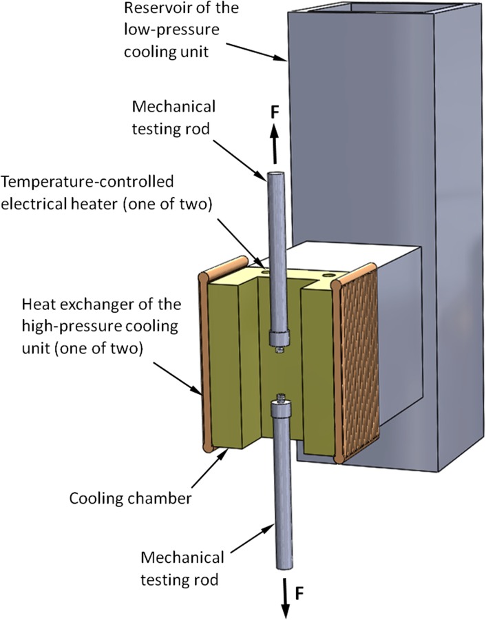
Schematic illustration of the key elements of the cooling mechanism for mechanical testing. During experimentation, the artery is attached to the mechanical testing rods (see Fig. 2), the cooling chamber is closed with a brass cover, and the system is covered with thermal insulation from all sides.
Mechanical testing of small-diameter blood vessels has been presented as a new challenge in the current study for two reasons: (i) the diameter of the blood vessels is smaller than the testing-rod diameter and (ii) heat conduction from the blood vessel to the testing rod (steel) created nonuniform thermal conditions along the specimen. To overcome this challenge, mechanical-rod thermal-isolators have been designed, as illustrated in Fig. 2. Figure 3 displays a specimen connected to the thermal insulators, placed in the cooling chamber, and ready for experimentation. Also displayed in Fig. 3 is the thick thermal insulation placed around the cooling chamber. Before experimentation, a chamber cover and a thick layer of thermal insulation are also placed between the specimen and the surroundings.
Fig. 2.
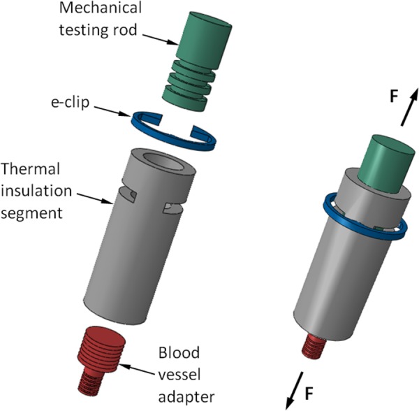
Schematic illustration of the mechanical-rods thermal insulators, which were designed to accommodate smaller diameter arteries
Fig. 3.
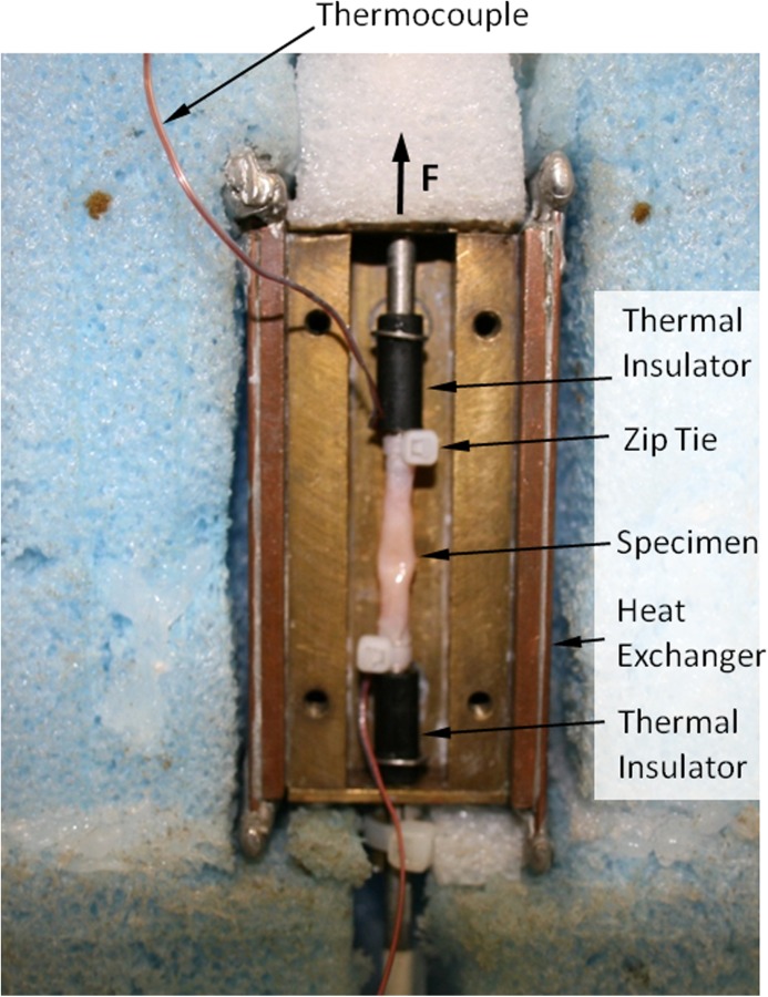
An artery sample placed in the cooling chamber and ready for testing, where the cover of the cooling chamber has to be installed and insulated before experimentation. Also shown are thermocouples connected to both ends of the sample, where an additional thermocouple at the center of the sample is yet to be placed.
The rod insulator is made in the shape of a Delrin cylinder, having an inner diameter of 4 mm, an outer diameter of 6 mm, and an overall length of 15 mm. The insulator is connected with an e-clip to the mechanical testing rod, while a threaded adapter is hosted at the other end, to accommodate smaller-diameter blood vessels. This design has reduced temperature nonuniformity along the specimen from 12 °C to 4 °C (as measured by thermocouples), by reducing the conductive heating effect of the specimen by the mechanical-testing rods.
Materials
All tissue samples used in this experiment were donated by a local slaughterhouse. In order to maintain tissue quality, blood vessel specimens were harvested by members of the research team shortly after the animal was slaughtered. No animals were sacrificed specifically for the purpose of the current study. A main carotid artery was harvested from goats to create samples for testing in a (inner) diameter range from 2.5 to 4.5 mm, a length range from 19 to 35 mm, all with a wall thickness of about 1 mm (wall thickness measurement technique is discussed below). Samples were immersed in SPS-1 organ preservation solution (Organ Recovery Systems, Inc., Itasca, IL) immediately after harvesting and stored at 4 °C for a period between one and five days. This range of wait times was necessary due to availability of specimens and based on this study and others [17–20], appeared to have no effect on experimental results. SPS-1 organ preservation solution is based on the University of Wisconsin solution [25] and is designed to prevent osmotic damage during short term refrigerated storage. Following the procedure outlined in Ref. [17], each specimen was immersed in the DP6 + SIM or 7.05M DMSO solution before testing. Each sample is placed within a vial containing 3 ml of full concentration CPA. The artery is allowed to drain and the CPA is forced through the artery using a syringe (to insure proper mixing) every 20 min. After 1 h, the artery is placed into a new 3 ml of full concentration CPA and the process is repeated for another hour.
DP6 is a cocktail of 234.4 g/L DMSO (3M), 228.3 g/L propylene glycol (3M), and 2.4 g/L HEPES in EuroCollins solution. While other CPAs have been found to be a much better at promoting vitrification [20,26], DP6 appears to be more promising due to its reduced overall CPA concentration, and therefore its toxicity. The drawback of reduced CPA concentration is the high cooling rate typically required for vitrification of DP6. Hence, this proposal focuses on DP6 combined with SIMs, in an effort to improve its tendency to promote vitrification.
There are many possible SIMs that could be tested, the particular ones chosen for this report were based on the experience of the current research team [12,17,18,27]. The following cocktails have been tested: DP6 + 12% PEG400 (n = 6), DP6 + 6% 1,3-CHD (n = 5), and DP6 + 6% 2,3-BD (n = 10) as well as 7.05M DMSO (n = 9) as a reference solution, where n is the number of specimens tested. All SIMs: PEG400, 1,3-CHD (98% mixture of cis and trans isomers), and 2,3-BD (2R,3R isomer), were obtained from Sigma-Aldrich (St. Louis, MO); DP6 was obtained from Cell and Tissue Systems, inc. (Charleston, SC).
Methods
Specimen Setup.
After CPA permeation is completed, the specimen is removed from the solution and held vertically to allow any CPA within the artery to drain. Next, it is placed between the two mechanical-rod thermal isolators (Fig. 2) and fastened with cable ties (3.94 in. miniature indoor cable tie) as displayed in Fig. 3. The length of the artery between the cable ties is measured with a caliper and T-type thermocouples are placed at the top, middle, and bottom of the artery before the cooling chamber is closed with a brass cover plate.
Experimental Protocol.
Before the onset of experimentation, the mechanical-testing system is set to zero load control and the temperature controller is set to 20 °C. Next, the low-pressure cooling unit is filled with liquid nitrogen, while the temperature controller maintains a cooling-chamber temperature of 20 °C, which facilitates precooling for the entire system. The thermal protocol starts by turning the controller off, while simultaneously activating the high-pressure cooling unit, with typical results displayed in Fig. 4. In practice, both low-pressure and high-pressure units are working in tandem in this stage, resulting in a high cooling rate sufficient to promote vitrification of the tested samples. Since the critical cooling rate to suppress crystallization needs to be exceeded throughout the domain, and since crystallization is most likely to occur between −30 °C and −90 °C, the cooling rate was measured for the slowest responding part of the blood vessel between those temperatures. The measured cooling rate between −30 °C and −90 °C is above 20 °C/min for all experiments, where the critical cooling rate for 7.05M DMSO is less than 1.4 °C/min and for DP6 without SIMs is 40 °C/min, which is why experiments from Ref. [23] excluded this cocktail. However, when DP6 is mixed with SIMs, the critical cooling rate is lower than 5 °C/min as shown in Ref. [17] which facilitates vitrification within the experimental conditions of the current system.
Fig. 4.
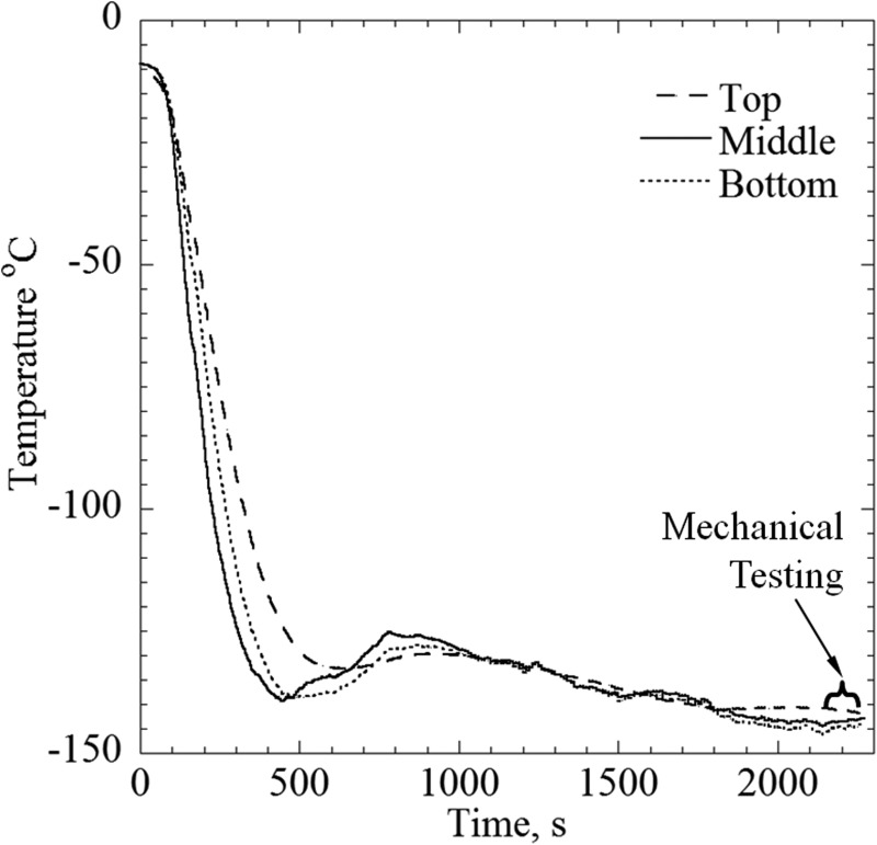
A typical thermal history for tensile testing experimentations
Once the specimen approaches the preselected testing temperature, the high-pressure cooling unit is deactivated and the temperature controller is reactivated to maintain the specimen at a mechanical-testing temperature. The mechanical-testing temperature range in the current study is between −145 °C and −155 °C, where the glass transition temperature for DP6 and 7.05M DMSO is −119 °C and −123 °C, respectively. Next, the cooling chamber is controlled to maintain the mechanical-testing temperature for an intermediate period of time, to allow the specimen and its holders to approach thermal equilibration. This intermediate time period is roughly between 400 s and 2150 s in the representative experiment displayed in Fig. 4. The slow-rate, low-magnitude rewarming between 400 s and 800 s is related to a higher order effect resulting from switching between two different cooling mechanisms, thermal inertia of their components, and the change in control parameters. Nevertheless, the temperature during that time period does not exceed the glass transition temperature, and the material can be considered solid over such an extremely short period of time in terms of glassy materials. Finally, the control of the mechanical-testing system is switched from zero-load control to displacement-rate control, subject to a constant rate of 2.54 μm/s until failure, which usually occurs within 80 s.
Cross Section Measurements.
Once the system has reached room temperature after completing a mechanical-testing experiment, the artery is removed from the cooling chamber and sectioned into four thin rings, approximately 1–2 mm thick. These rings are selected away from the top or bottom of the specimen (i.e., the location of the cable ties), and also away from the specimen failure site. Next, the rings are placed on a black background, next to a ruler, and two pictures are taken as displayed in Fig. 5. Using the image processing tool imtool of matlab and the ruler (Fig. 5(a)), the number of pixels per unit area is determined. The images are then converted to black and white (Fig. 5(b)) and cropped for each artery (Fig. 5(c)). Next, the cross-sectional area for each processed artery image is calculated via pixel counting. Finally, the process is repeated for the second picture of the same rings, and the characteristic area for further analysis is taken as the average of all the cross sections, from a total of eight images.
Fig. 5.
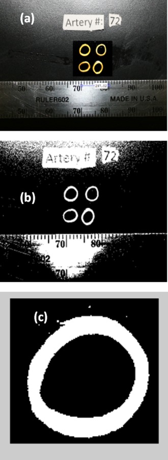
Images used to calculate the cross-sectional area of the artery specimens, including: (a) a stills image of four representative segments and a ruler, to determine area per pixel; (b) a black and white processed image; and (c) an isolated segment used for pixel counting
Results and Discussion
Three representative stress–strain experimental cases are displayed in Fig. 6. Case 1 resembles linear-elastic behavior, which exhibits a sudden stress drop at the point of fracture. All of the specimens permeated with 7.05M DMSO, DP6 + 1,3-CHD, and DP6 + 2,3-BD exhibited the same behavior. While most of the specimens permeated with DP6 + PEG400 also exhibited the same behavior, selected exceptions are also illustrated in Fig. 6, where the response in case 2 resembles a strain-hardening behavior and the response in case 3 may be related to plastic deformations. To remove any doubt, it is emphasized that all three specimens were subject to the same CPA loading protocol, thermal history, and mechanical loading procedure. While the authors cannot currently offer definitive explanations to those exceptional responses, they may be related to aspects of mass-transport during the permeation phase, or to localized crystallization in the tissue, which may be more relevant to DP6 + PEG400. Note that early characterizations of the above CPA cocktails were done on small specimens (a differential scanning calorimeter sample size) and in the absence of biological materials, while the current line of investigation focuses for the first time on bulky specimens.
Fig. 6.
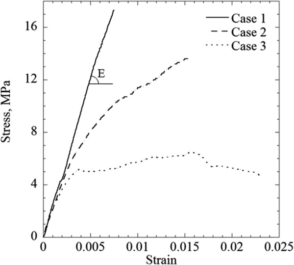
Three typical stress–strain curves obtained in the current study: (case 1) representing the linear-elastic behavior found for specimens permeated with all solutions except for the cocktail DP6 + PEG400; (case 2) a possibly hardening specimen, permeated with DP6 + PEG400; and (case 3) a specimen permeated with DP6 + PEG400, possibly exhibiting viscous flow or plastic deformations
In order to study the behavior of the material under repeated loading cycles, several specimens were exposed to such a protocol before failure, where Figs. 7(a) and 7(b) display the loading and unloading portions of a representative protocol, respectively. In general, the same linear-elastic behavior was maintained throughout the three consecutive loading cycles displayed in Fig. 7(a). A closer inspection of the stress–strain curves reveals three steplike changes in strain, labeled A for the first loading cycle, and labeled B and C for the second loading cycle. In the following respective loading cycles, the stress–strain curves coincided at stress levels higher than the respective points—Loads 1 and 2 above point A, and Loads 2 and 3 above point C. Furthermore, these localized incidents did not change the slope of the stress–strain curve (i.e., the Young's modulus), suggesting that the bulk behavior of the specimen has been preserved. It is plausible that the physical event causing such a steplike change in strain is the formation of a microfracture, where the area of the fracture is much smaller than the cross-sectional area of the specimen. A similar behavior has been observed under compression in frozen tissues in the absence of CPAs, where the presence of fractures has been verified using routine histology techniques [28,29]. Figure 7(b) displays deviation from the classical linear-elastic behavior during unloading, but the same unloading pattern is preserved between consecutive cycles. It can be concluded from Figs. 7(a) and 7(b) that no gross damage has occurred prior to the dramatic macrofracture that defined the end of the specific experiment.
Fig. 7.
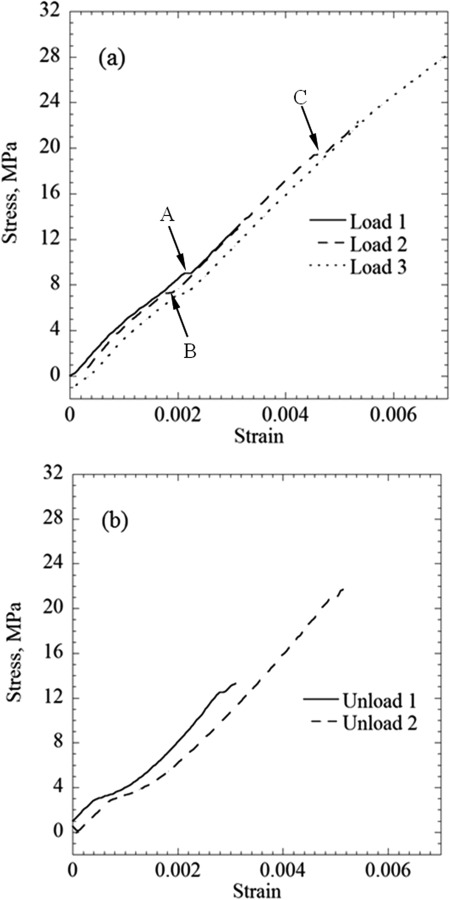
Results of repeated loading–unloading cycles of a blood vessel specimen permeated with DP6 + 12% PEG400: (a) the loading portions of the protocol and (b) the unloading portions of the protocol; labels A, B, and C points to steplike changes of strain, possibly associated with the formation of microfractures
In all experiments, the macrofracture at the end of load testing appeared with clear edges, at the transverse direction to the artery axis. This observation can be explained by one or more of the following reasons: (i) A brittle material under tension tends to fracture along the plane of maximum tensile stress, which is the transverse cross section under uniaxial loading. (ii) Structural failure may follow cell boundaries, which have a circumferential preference in a blood vessel, allowing it to constrict and expand as needed [8].
In a previous study, Jimenez and Rabin measured Young's Modulus of arteries permeated with 7.05M DMSO and VS55, as well as frozen arteries in the absence of CPAs [23]. For arteries permeated with 7.05M DMSO, Jimenez and Rabin measured the Young's Modulus in the range of 823 and 1039 MPa, while results of the current study suggest the Young's Modulus to be in the range of 922 and 2955 MPa. While the lower range values are quite close in both studies, the upper range value in the current study is threefold higher than that in the previous study. The differences between the two studies are the number of specimens (n = 4 in Ref. [23] as opposed to n = 9 in the current study), and the diameter of the blood vessels is 1–2 mm smaller in the current study. The smaller diameter indicates younger animals, but there is no good documentation to the animal ages for those donated specimens. Closer investigation of the differences reveals that the stress–strain behavior reported in Ref. [23] more resembles case 2 than case 1 in Fig. 6, which was found atypical to 7.05M DMSO in the current study. Perhaps this difference is also associated with the lower temperature uniformity in the absence of thermal insulators (Fig. 2) in Ref. [23]. Interestingly, despite all of the differences listed above, the average fracture stresses as measured in the current study are similar to those measured by Jimenez-Rios and Rabin [23]. For the current study, the range of fracture stress is between 6.65 and 19.7 MPa with an average of 13.31 ± 3.74 MPa, which is wider than the range measured in Ref. [23], which was between 10.46 and 15.74 MPa, with an average of 12.96 ± 2.03 MPa. This range is particularly wide due to a few outliers, when comparing average fracture stresses between the two studies, the difference is only about 15%.
Table 1 provides a summary of all of experimental results. The arteries permeated with DP6 + 6% 2,3-BD exhibited the highest average Young's modulus. However, the variance within each group is high compared with the average difference between the various groups, and no statistical conclusions could be drawn based on a Student's t-test. The current study extends the available knowledge on mechanical properties of vitrified blood vessels at very low temperature [23,24], where no other comparable data has been published elsewhere to the best of the authors' knowledge. By contrast, numerous other studies have measured mechanical properties of blood vessels at room temperature temperatures [30,31]—the only available group of reference. It is difficult to compare those studies, where the blood vessels behave hyperelastically, with the current study, but it is interesting to note that the variation in measured mechanical properties in those studies is comparable with the variation in Young's modulus measurements in the current study. It has been suggested previously [23] that the mechanical properties of the vitrified CPA may dominate the behavior of the complex system of CPA-permeated tissue. By contrast, the wide variance of Young's modulus measured in this study, as well as the variance in mechanical properties measured in Refs. [30,31], suggests that the tissue structure may actually play a noticeable role in the mechanical response of the CPA-tissue system.
Table 1.
Summary of experimental data
| Sample No. | L (mm) | A (mm2) | T (°C) | έ × 104 (s−1) | Δε × 103 | E (MPa) | R 2 | Failure stress (MPa) | |
|---|---|---|---|---|---|---|---|---|---|
| PEG400 | 1 | 35.00 | 8.84 | −149.3 | 0.73 | 0.07 | 2279 | 0.999 | 6.99 |
| 2 | 31.66 | 7.54 | −145.0 | 0.80 | 3.60 | 2475 | 0.999 | 11.21 | |
| 3 | 26.48 | 8.04 | −139.8 | 0.96 | 1.91 | 2006 | 0.999 | 9.67 | |
| 4 | 26.00 | 7.04 | −143.0 | 0.98 | 2.34 | 2479 | 1.000 | 12.58 | |
| 5 | 30.42 | 8.84 | −139.8 | 0.84 | 2.41 | 2001 | 0.999 | 12.44 | |
| 6 | 23.26 | 8.27 | −143.9 | 1.09 | 6.21 | 2426 | 0.999 | 15.91 | |
| Average | 28.80 | 8.10 | −143.46 | 0.90 | 2.07 | 2248 ± 224 a | 0.999 | 10.58 ± 3.01 a | |
| 7.05 M DMSO | 1 | 28.00 | 9.40 | −150.0 | 0.91 | 6.35 | 922 | 0.999 | 7.38 |
| 2 | 25.70 | 10.33 | −147.5 | 0.99 | 5.58 | 950 | 0.999 | 9.80 | |
| 3 | 31.34 | 10.72 | −153.9 | 0.81 | 6.88 | 1011 | 0.999 | 12.22 | |
| 4 | 25.93 | 8.98 | −142.9 | 0.98 | 10.30 | 1495 | 1.000 | 15.68 | |
| 5 | 31.21 | 6.78 | −167.7 | 0.81 | 1.83 | 2955 | 0.999 | 14.81 | |
| 6 | 21.68 | 9.44 | −146.2 | 1.17 | 7.88 | 1839 | 0.999 | 13.89 | |
| 7 | 30.48 | 11.30 | −148.6 | 0.83 | 4.99 | 2240 | 0.999 | N/A | |
| 8 | 24.67 | 7.26 | −163.1 | 1.03 | 4.61 | 2700 | 0.999 | 18.01 | |
| 9 | 22.71 | 12.50 | −138.2 | 1.12 | 8.15 | 1631 | 0.999 | 12.44 | |
| Average | 28.44 | 9.24 | −152.39 | 0.90 | 6.19 | 2143 ± 754 a | 0.999 | 11.98 ± 3.36 a | |
| 1,3-CHD | 1 | 27.39 | 10.49 | −151.0 | 0.93 | 2.32 | 1480 | 1.000 | 9.59 |
| 2 | 22.46 | 8.03 | −142.8 | 1.11 | 7.03 | 2080 | 0.999 | 17.96 | |
| 3 | 24.48 | 8.11 | −150.0 | 1.04 | 2.69 | 2310 | 1.000 | 10.07 | |
| 4 | 27.19 | 8.31 | −144.3 | 0.93 | 3.06 | 1777 | 0.999 | 6.65 | |
| 5 | 25.63 | 8.66 | −145.5 | 0.99 | 2.46 | 2448 | 0.999 | 15.92 | |
| Average | 25.43 | 8.72 | −146.7 | 1.00 | 3.51 | 2019 ± 394 a | 0.999 | 12.04 ± 4.72 a | |
| 2,3BD | 1 | 21.31 | 7.21 | −148.3 | 1.19 | 2.14 | 2940 | 0.999 | 12.83 |
| 2 | 28.31 | 10.71 | −143.3 | 0.90 | 1.77 | 2868 | 0.999 | 10.05 | |
| 3 | 29.07 | 8.80 | −146.0 | 0.87 | 1.66 | 3012 | 1.000 | 19.72 | |
| 4 | 22.68 | 6.93 | −153.0 | 1.12 | 3.95 | 2811 | 0.999 | 18.68 | |
| 5 | 19.35 | 8.15 | −144.2 | 1.31 | 5.10 | 2062 | 0.999 | 15.64 | |
| 6 | 24.24 | 9.79 | −147.0 | 1.04 | 5.27 | 1688 | 0.999 | 14.65 | |
| 7 | 24.26 | 8.67 | −141.0 | 1.05 | 5.22 | 2298 | 0.999 | 19.32 | |
| 8 | 19.07 | 8.62 | −151.7 | 1.33 | 1.92 | 1675 | 0.999 | 12.19 | |
| 9 | 24.01 | 8.52 | −149.8 | 1.06 | 7.38 | 2416 | 0.999 | 16.46 | |
| Average | 23.59 | 8.60 | −147.14 | 1.10 | 3.82 | 2419 ± 525 a | 0.999 | 15.50 ± 3.39 a | |
| Frozen | 1 | 23.29 | 9.79 | −146.1 | 1.09 | 4.84 | 1226 | 0.996 | 5.25 |
Standard deviation
Summary and Conclusion
This study aims at measuring the Young's modulus in vitrified blood vessels below the glass transition temperature, in conditions relevant to cryogenic storage. This study expands on previously developed data [24], with the unique contribution of testing CPAs mixed with SIMs, a group of compounds of increasing interest in the cryobiology community. The effect of SIMs on the mechanical behavior of the vitrified biomaterial is largely unknown. The experimental apparatus used in the current study has been developed previously [23], and combines a new modification in the form of thermal insulator to: (i) improve temperature uniformity within the specimen and (ii) facilitate mechanical testing at lower temperatures.
Results of this study indicate a linear-elastic behavior of the vitrified specimens below glass transition. This behavior is regained under repeated loading/unloading cycles. Small steplike strain changes have been observed during the loading without affecting the bulk behavior of the specimen, suggesting microfracture occurrences. This observation agrees with previous observation on microfracture formation under compression in the absence of CPA and SIMs. While small deviation from the classical linear-elastic model during unloading has been observed, this behavior is repeatable and indicates no permanent damage to the specimen due to loading before the dramatic specimen failure defining the end of experimentation.
Results of this study indicate a Young's modulus in the range of 0.92–3.01 GPa, with no clear indication that the different SIMs affect the Young's modulus value differently. It is suggested that this range of values is attributed to variations between specimens of the same species and not to the SIMs. Results of this study suggest that past computations of mechanical stress during vitrification may have used values from the lower end of the measured range, most frequently 1 GPa [5,26,32,33]. This is important for future analysis mechanical stress for cryopreservation by vitrification.
Acknowledgment
This project has been supported in part by Award No. 1R21EB011751 from the National Institute of Biomedical Imaging and Bioengineering, and in part by a National Science Foundation Graduate Research Fellowship under Grant No. DGE-1252522. The content of this paper is solely the responsibility of the authors and does not necessarily represent the official views of the National Institute of Biomedical Imaging and Bioengineering, the National Institutes of Health, or the National Science Foundation.
Contributor Information
David P. Eisenberg, Biothermal Technology Laboratory, Department of Mechanical Engineering, Carnegie Mellon University, Pittsburgh, PA 15232, e-mail: deisenbe@andrew.cmu.edu
Yoed Rabin, Biothermal Technology Laboratory, Department of Mechanical Engineering, Carnegie Mellon University, Pittsburgh, PA 15232, e-mail: rabin@cmu.edu .
References
- [1]. Song, Y. C. , Khirabadi, B. S. , Lightfoot, F. G. , Brockbank, K. G. M. , and Taylor, M. J. , 2000, “Vitreous Cryopreservation Maintains the Function of Vascular Grafts,” Nat. Biotechnol., 18(3), pp. 296–299. 10.1038/73737 [DOI] [PubMed] [Google Scholar]
- [2]. Fahy, G. M. , 1987, “Biological Effects of Vitrification and Devitrification,” in The Biophysics of Organ Preservation, edited by Pegg D. E. and A. M. Karow, Jr. , Plenum Publishing Corporation, New York, pp. 265–297. [Google Scholar]
- [3]. Karow, A. M. , 1981, “Biophysical and Chemical Considerations in Cryopreservation,” in Organ Preservation for Transplantation, edited by Karow A. M. and Pegg D. E., Dekker, New York, pp. 113–141. [Google Scholar]
- [4]. Taylor, M. J. , 1987, “Physico-Chemical Principles of Low Temperature Biology,” in The Effects of Low Temperatures on Biological System, edited by Grout B. W. W. and Morris J. G., Edward Arnold, London, pp. 3–71. [Google Scholar]
- [5]. Rabin, Y. , Steif, P. S. , Hess, K. C. , Jimenez-Rios, K. C. , and Palastro, K. C. , 2006, “Fracture Formation in Vitrified Thin Films of Cryoprotectants,” Cryobiology, 53(1), pp. 75–95. 10.1016/j.cryobiol.2006.03.013 [DOI] [PMC free article] [PubMed] [Google Scholar]
- [6]. Steif, P. S. , Palastro, M. , We, C. R. , Baicu, S. , Taylor, M. J. , and Rabin, Y. , 2005, “Cryomacroscopy of Vitrification, Part II: Experimental Observations and Analysis of Fracture Formation in Vitrified VS55 and DP6,” Cell Preserv. Technol., 3(3), pp. 184–200. 10.1089/cpt.2005.3.184 [DOI] [PMC free article] [PubMed] [Google Scholar]
- [7]. Kasai, M. , Zhu, S. E. , Pedro, P. B. , Nakamura, N. , Sakurai, T. , and Edashige, K. , 1996, “Fracture Damage of Embryos and Its Prevention During Vitrification,” Cryobiology, 33(4), pp. 459–464. 10.1006/cryo.1996.0046 [DOI] [PubMed] [Google Scholar]
- [8]. Pegg, D. E. , Wusteman, M. , and Boylan, S. , 1997, “Fractures in Cryopreserved Elastic Arteries,” Cryobiology, 34(2), pp. 183–192. 10.1006/cryo.1996.1997 [DOI] [PubMed] [Google Scholar]
- [9]. Rajamohan, A. , and Leopold, R. A. , 2007, “Cryopreservation of Mexican Fruit Flies by Vitrification: Stage Selection and Avoidance of Thermal Stresses,” Cryobiology, 54(1), pp. 44–54. 10.1016/j.cryobiol.2006.10.192 [DOI] [PubMed] [Google Scholar]
- [10]. Fahy, G. M. , 2004, “Methods of Using Ice-Controlling Molecules, Organ Recovery Systems, Inc.,” U.S. Patent No. 6,773,877.
- [11]. Taylor, M. J. , Song, Y. C. , and Brockbank, K. G. M. , 2004, “Vitrification in Tissue Preservation: New Developments,” in Life in the Frozen State, edited by Fuller B. J., Lane N., and Benson E., Taylor and Francis Books, London, pp. 603–642. [Google Scholar]
- [12]. Taylor, M. J. , and Baicu, S. , 2009, “Review of Vitreous Islet Cryopreservation: Some Practical Issues and Their Resolution,” Organogenesis, 5(3), pp. 155–166. 10.4161/org.5.3.9812 [DOI] [PMC free article] [PubMed] [Google Scholar]
- [13]. Wowk, B. , Leitl, E. , Rasch, C. M. , Mesbah-Karimi, N. , Harris, S. B. , and Fahy, G. M. , 2000, “Vitrification Enhancement by Synthetic Ice Blocking Agents,” Cryobiology, 40(3), pp. 228–236 10.1006/cryo.2000.2243 [DOI] [PubMed] [Google Scholar]
- [14]. Budke, C. , and Koop, T. , 2006, “Ice Recrystallization Inhibition and Molecular Recognition of Ice Faces by Poly(Vinyl Alcohol),” ChemPhysChem, 7(12), pp. 2601–2606. 10.1002/cphc.200600533 [DOI] [PubMed] [Google Scholar]
- [15]. Inada, T. , and Modak, P. R. , 2006, “Growth Control of Ice Crystals by Poly(Vinyl Alcohol) and Antifreeze Protein in Ice Slurries,” Chem. Eng. Sci., 61(10), pp. 3149–3158. 10.1016/j.ces.2005.12.005 [DOI] [Google Scholar]
- [16]. Inada, T. , and Lu, S. , 2004, “Thermal Hysteresis Caused by Non-Equilibrium Antifreeze Activity of Poly(Vinyl Alcohol),” Chem. Phys. Lett., 394(4–6), pp. 361–365. 10.1016/j.cplett.2004.07.021 [DOI] [Google Scholar]
- [17]. Eisenberg, D. P. , Taylor, M. J. , and Rabin, Y. , 2012, “Thermal Expansion of Cryoprotective Cocktail, DP6, Combined With Synthetic Ice Modulators in the Presence and Absence of Biological Tissues,” Cryobiology, 65(2), pp. 117–125. 10.1016/j.cryobiol.2012.04.011 [DOI] [PMC free article] [PubMed] [Google Scholar]
- [18]. Eisenberg, D. P. , Taylor, M. J. , Jimenez-Rios, J. L. , and Rabin, Y. , 2014, “Thermal Expansion of Vitrified Blood Vessels Permeated With DP6 and Synthetic Ice Modulators,” Cryobiology, 68(3), pp. 318–326. 10.1016/j.cryobiol.2014.04.010 [DOI] [PMC free article] [PubMed] [Google Scholar]
- [19]. Jimenez-Rios, J. L. , and Rabin, Y. , 2006, “Thermal Expansion of Blood Vessels in Low Cryogenic Temperatures. Part II: Measurements of Blood Vessels Vitrified With VS55, DP6, and 7.05M DMSO,” Cryobiology, 52(2), pp. 284–294. 10.1016/j.cryobiol.2005.12.006 [DOI] [PMC free article] [PubMed] [Google Scholar]
- [20]. Rabin, Y. , and Plitz, J. , 2005, “Thermal Expansion of Blood Vessels and Muscle Specimens Permeated With DMSO, DP6, and VS55 in Cryogenic Temperatures,” Ann. Biomed. Eng., 33(9), pp. 1213–1228. 10.1007/s10439-005-5364-0 [DOI] [PubMed] [Google Scholar]
- [21]. Ehrlich, L. E. , Feig, J. S. G. , Schiffres, S. N. , Malen, J. A. , and Rabin, Y. , 2013, “Integration of Transient Hot-Wire Method into Scanning Cryomacroscopy in the Study of Thermal Conductivity of Dimethyl Sulfoxide,” Cryobiology, 67(3), p. 401. 10.1016/j.cryobiol.2013.09.022 [DOI] [Google Scholar]
- [22]. Noday, D. A. , Steif, P. S. , and Rabin, Y. , 2009, “Viscosity of Cryoprotective Agents Near Glass Transition: A New Device, Technique, and Data on DMSO, DP6, and VS55,” Exp. Mech., 49(5), pp. 663–672. 10.1007/s11340-008-9191-8 [DOI] [PMC free article] [PubMed] [Google Scholar]
- [23]. Jimenez-Rios, J. L. , and Rabin, Y. , 2007, “A New Device for Mechanical Testing of Blood Vessels at Cryogenic Temperatures,” Exp. Mech., 47(3), pp. 337–346. 10.1007/s11340-007-9038-8 [DOI] [PMC free article] [PubMed] [Google Scholar]
- [24]. Jimenez Rios, J. L. , Steif, P. S. , and Rabin, Y. , 2007, “Stress-Strain Measurements and Viscoelastic Response of Blood Vessels Cryopreserved by Vitrification,” Ann. Biomed. Eng., 35(12), pp. 2077–2086. 10.1007/s10439-007-9372-0 [DOI] [PMC free article] [PubMed] [Google Scholar]
- [25]. Southard, J. H. , and Belzer, F. O. , 1995, “Organ Preservation,” Annu. Rev. Med., 46, pp. 235–237. 10.1146/annurev.med.46.1.235 [DOI] [PubMed] [Google Scholar]
- [26]. Rabin, Y. , Taylor, M. J. , Walsh, J. R. , Baicu, S. , and Steif, P. S. , 2005, “Cryomacroscopy of Vitrification, Part I: A Prototype and Experimental Observations on the Cocktails VS55 and DP6,” Cell Preserv. Technol., 3(3), pp. 169–183. 10.1089/cpt.2005.3.169 [DOI] [PMC free article] [PubMed] [Google Scholar]
- [27]. Eisenberg, D. P. , Steif, P. S. , and Rabin, Y. , 2014, “On the Effects of Thermal History on the Development and Relaxation of Thermo-Mechanical Stress in Cryopreservation,” Cryogenics, 64, pp. 86–94. 10.1016/j.cryogenics.2014.09.005 [DOI] [PMC free article] [PubMed] [Google Scholar]
- [28]. Rabin, Y. , Olson, P. , Taylor, M. J. , Steif, P. S. , Julian, T. B. , and Wolmark, N. , 1997, “Gross Damage Accumulation on Frozen Rabbit Liver Due to Mechanical Stress at Cryogenic Temperatures,” Cryobiology, 34(4), pp. 394–405. 10.1006/cryo.1997.2010 [DOI] [PubMed] [Google Scholar]
- [29]. Rabin, Y. , Steif, P. S. , Taylor, M. J. , Julian, T. B. , and Wolmark, N. , 1996, “An Experimental Study of the Mechanical Response of Frozen Biological Tissues at Cryogenic Temperatures,” Cryobiology, 33(4), pp. 472–482. 10.1006/cryo.1996.0048 [DOI] [PubMed] [Google Scholar]
- [30]. Gamble, G. , Zorn, J. , Sanders, G. , MacMahon, S. , and Sharpe, N. , 1994, “Estimation of Arterial Stiffness, Compliance, and Distensibility From M-mode Ultrasound Measurements of the Common Carotid Artery,” Stroke, 25(1), pp. 11–16. 10.1161/01.STR.25.1.11 [DOI] [PubMed] [Google Scholar]
- [31]. Zhou, J. , and Fung, Y. C. , 1997, “The Degree of Nonlinearity and Anisotropy of Blood Vessel Elasticity,” Proc. Natl. Acad. Sci. U.S.A., 94(26), pp. 4255–14260. 10.1073/pnas.94.26.14255 [DOI] [PMC free article] [PubMed] [Google Scholar]
- [32]. Steif, P. S. , Palastro, M. C. , and Rabin, Y. , 2007, “Analysis of the Effect of Partial Vitrification on Stress Development in Cryopreserved Blood Vessels,” Med. Eng. Phys., 29(6), pp. 661–670. 10.1016/j.medengphy.2006.07.010 [DOI] [PMC free article] [PubMed] [Google Scholar]
- [33]. Steif, P. S. , Palastro, M. C. , and Rabin, Y. , 2007, “The Effect of Temperature Gradients on Stress Development During Cryopreservation Via Vitrification,” Cell Preserv. Technol., 5(2), pp. 104–115. 10.1089/cpt.2007.9994 [DOI] [PMC free article] [PubMed] [Google Scholar]


