Abstract
Objective
Minimally-invasive, image-guided cochlear implantation (CI) utilizes a patient-customized microstereotactic frame to access the cochlea via a single drill-pass. We investigate the average force and trauma associated with the insertion of lateral wall CI electrodes using this technique.
Study Design
Assessment using cadaveric temporal bones
Setting
Laboratory setup
Subjects and Methods
Microstereotactic frames for six fresh cadaveric temporal bones were built using CT scans to determine an optimal drill path following which drilling was performed. CI electrodes were inserted using surgical forceps to manually advance the CI electrode array, via the drilled tunnel, into the cochlea. Forces were recorded using a six-axis load sensor placed under the temporal bone during the insertion of lateral wall electrode arrays (two each of Nucleus CI422, MED-EL standard, and modified MED-EL electrodes with stiffeners). Tissue histology was performed by microdissection of the otic capsule and apical photo-documentation of electrode position and intracochlear tissue.
Results
After drilling, CT scanning demonstrated successful access to cochlea in all six bones. Average insertion forces ranged from 0.009 to 0.078N. Peak forces were in the range of 0.056–0.469N. Tissue histology showed complete scala tympani insertion in five specimens and scala vestibuli insertion in the remaining specimen with depth of insertion ranging from 360–600°. No intracochlear trauma was identified.
Conclusion
The use of lateral wall electrodes with the minimally-invasive, image-guided CI approach was associated with insertion forces comparable to traditional CI surgery. Deep insertions were obtained without identifiable trauma.
Keywords: Cochlear implantation, cochlear histology, cochlear electrode, insertion forces, minimally-invasive surgery
Introduction
Cochlear implants (CI) are the standard of care for treatment of severe to profound bilateral sensorineural hearing loss. The traditional surgical approach, first described by CI pioneer William House, involves mastoidectomy followed by posterior tympanotomy to provide access to the basal turn of the cochlea. This technique is well known to surgeons comfortable with facial recess anatomy. For surgeons more comfortable with endaural approaches to middle ear pathology, the suprameatal approach was developed1,2. This approach uses anatomical measurements from the surface of the temporal bone to estimate and drill a tunnel to access the attic. Following this drilling, the middle ear is addressed via a tympanomeatal flap, an entry into the cochlea is made via either the round window (RW) or a separate cochleostomy, and the CI electrode passed from the tunnel to the attic and then threaded into the cochlea. This approach is limited to highly-flexibe, lateral wall electrodes and is not suitable for styleted, perimodiolar electrodes. Over 500 suprameatal approaches have been reported in the literature.
Perhaps the biggest downside to the suprameatal approach is the suboptimal insertion vector as the electrode must be redirected as it courses from the attic to the hypotympanum and ultimately into the cochlea. Capitalizing on image-guidance technology to provide a tunnel through the facial recess and preserve an optimal insertion vector, our group has developed and reported on a minimally-invasive, image-guided implantation technique previously called Percutaneous Cochlear Implantation (PCI). Validated in vitro3–5 and in vivo6,7, this approach utilizes CT imaging to specify a trajectory that allows access to the cochlea via a single drill-pass from the lateral skull through the facial recess to an optimal insertion point in the scala tympani (ST) subcomponent of the cochlea. The specified trajectory is accurately drilled on patients through the use of a patient-customized, microstereotactic frame, which is affixed to the skull of the patient using bone-implanted markers that serve both as fiducial markers to register the patient to their CT scan and as mounting points for the microstereotactic frame. While accuracy for this technique has been determined to be in the submillimetric range (target registration error of the system is 0.37 ± 0.18 mm 5), force associated with insertion of electrode arrays with this technique has yet to be determined in comparison to traditional surgical approaches. Thus, the overall purpose of this study was to assess the forces and potential intracochlear trauma associated with the insertion of electrodes via the minimally-invasive, image-guided CI approach. More specifically, this study aims to assess the insertion impact of three different electrode types by analysis of intraoperative force data, post-operative electrode placement status, and intra-cochlear trauma outcomes via the minimally-invasive, image-guided CI technique.
Methods
Six fresh cadaveric temporal bones were harvested for use in this study. No institutional IRB approval was required as the research involved post-mortem specimens. As histological processing of the samples was an important objective of the study, fresh specimens were obtained within 120 hours of death, placed in buffered formalin, and transported. Tympanomeatal flap was raised and the stapes removed to allow formalin to enter the inner ear to preserve structures. Bones were then refrigerated for the short interval—several days—between arrival of specimens and the experimentation described below.
The minimally-invasive, image-guided approach to access the cochlea was completed by performing the following steps on individual specimens:
Step 1- Three fiducial markers were bone-implanted in each sample at the mastoid tip, supra-helical region, and posterior auricular area (Figure 1).
Step 2- CT image of the sample covering the entire specimen with the fiducial markers was acquired using an xCAT ENT mobile CT scanner (Xoran Technologies Inc., Ann Arbor, MI, USA).
Step 3- Automatic segmentation of critical structures in the CT scan, including the facial nerve, the chorda typmani, and the cochlea, was performed8,9. A safe linear drill trajectory was then automatically planned from the lateral skull to the cochlea through the facial recess10. This trajectory was independently confirmed by a study investigator for each bone specimen and drilling depths along the path for the different diameter drill bits mentioned in Step 6 were determined (Figure 2).
Step 4- A custom microstereotactic frame was designed and constructed for each specimen using a standard computer numeric control (CNC) milling machine. The frame was fabricated in approximately five minutes using data created by custom software written in Matlab (Mathworks, Natick, MA, USA) that specifies the exact dimensions necessary in order to mount the frame on the fiducial markers and drill the desired trajectory.
Step 5 – To provide direct visualization to the middle ear, a tympanomeatal flap was raised and the RW overhang was drilled away to allow complete visualization of the RW membrane..
Step 6- The microstereotactic frame was installed onto the fiducial markers and was used to guide a custom manual drill press. The desired trajectory was drilled using a 3.8 mm twist drill bit laterally and a 1.6 mm twist drill bit medially3. The wider lateral hole allows irrigation during deeper drilling and placement of a bushing for the thinner drill bit closer to the facial recess and cochlea to perform accurate drilling that will be safe to the structures. The drill press was set to limit the depth of drilling based on the measurements in the CT scan to prevent any damage to critical structures. In general, the lateral drilling was set to stop with about 5 mm safety distance from the facial recess and the medial drilling was set to stop in the middle ear region. A cochleostomy was then performed by replacing the twist drill bit with a 1mm spherical diamond drill bit to minimize damage to the cochlea11. Opening of the cochlea was confirmed microscopically prior to moving forward.
Figure 1.
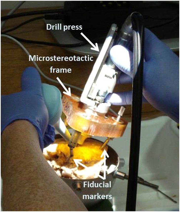
Drilling using custom microstereotactic frame on a temporal bone specimen. Bone-implanted fiducial markers allow rigid attachment of the frame to the specimen.
Figure 2.
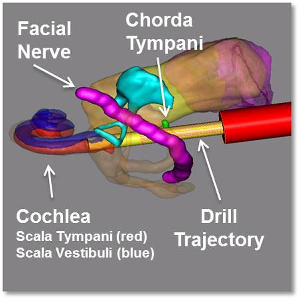
Three-dimensional rendering of the segmented structures and the drill path. The red cylinder along the drill path represents the determined depth for stopping the lateral drilling.
To ensure consistency among the force and trauma data obtained for each electrode type, the same surgeon performed all the insertions. Two of each Nucleus CI422 electrodes (Cochlear Ltd., Sydney, Australia), MED-EL standard electrodes (MED-EL GmbH, Innsbruck, Austria), and MED-EL custom electrodes with stiffeners were used in this experiment. The MED-EL custom electrodes were developed in cooperation with the manufacturer by adding four nitinol stiffening rods in the silicone surrounding the extra-cochlear transmitting wire from the internal receiver to the beginning of the electrode array (Figure 3). Prior experience had shown the standard MED-EL electrode type to be quite flexible12 and the stiffening rods were added to assess any change in the depth of insertion by using a more rigid prototype.
Figure 3.

The design of the MED-EL custom electrode. Four nitinol stiffening rods were added in the silicone surrounding the extra-cochlear transmitting wire from the internal receiver to the beginning of the electrode array.
Each specimen was placed on the load sensor to collect forces (Figure 4). The sensor used was a Nano43 6-axis force and moment transducer with a resolution of 0.004 Newtons (N) and sampling rate of 2 kHz (ATI Industrial Automation Inc., Apex, NC, USA). After a specimen was placed on the surface of the sensor, the output force was tarred to zero. Any additional force onto the sensor was assumed to be applied by contact with the implant or the surgeon. Force and moment data were recorded and analyzed using custom-written MATLAB software (MathWorks Inc., Natick, MA, USA).
Figure 4.
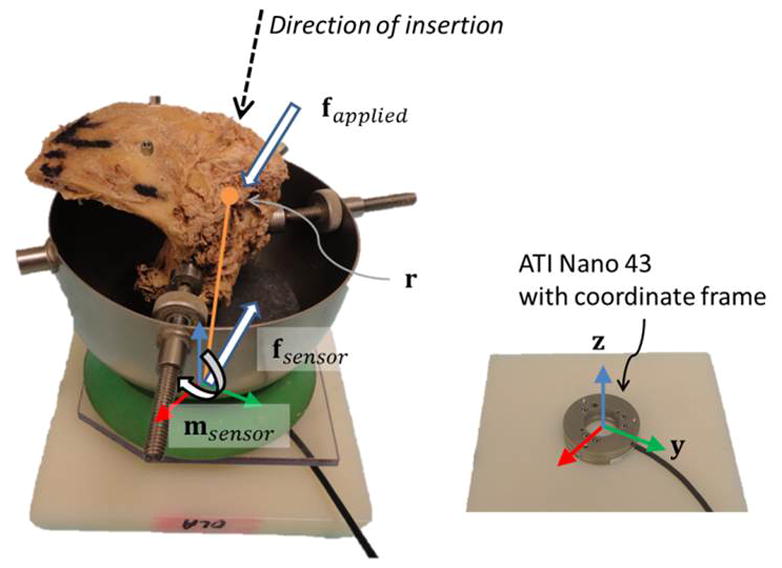
Experimental Setup. The temporal bone (left image) was placed on the Nano43 force sensor (right image). The sensor coordinate frame and representative illustration of the insertion direction, point of contact, forces, and moment are included.
Each insertion was monitored via two methods. The surgeon used a microscope placed directly above the drill hole to guide advancement of the electrode. Additionally, another view was available via an endoscope placed in the external auditory meatus and secured with an endoscope holder such that it did not contact the specimen (i.e. did not contribute force to the load sensor). The endaural approach was not used at the time of the insertion other than to provide visualization that the electrode was entering the cochlea. Electrodes were inserted until the surgeon felt additional force would cause damage. At this point, a small amount of cyanoacrylate glue was applied to secure the electrode to the cochleostomy in order to limit electrode movement during the next steps.
Immediate post-insertion CT imaging was performed to assess electrode array placement. Following this step, cochleae were harvested from the temporal bones using a sagittal oscillating saw (Stryker Corporation, Kalamazoo, MI, USA). The samples then underwent microdissection and staining following a procedure that has been previously detailed elsewhere13. Briefly, the membranous labyrinth was stained with osmium tetroxide to allow for visualization of nerve fibers. The bone overlying the ST was decalcified and carefully removed followed by removal of Reissner’s membrane. These steps allow a clear view of the basilar membrane and the underlying ST. The structures within the inner ear were carefully examined and photographed to assess for any structural trauma.
Results
Location and histopathology results
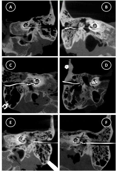
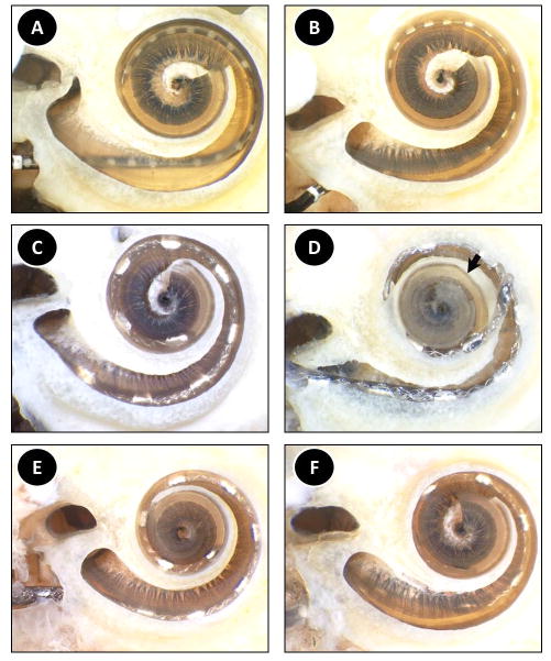
Post-insertion CT imaging revealed all six electrodes coursed through the cochlea (Figure 5). The facial nerve was intact after drilling in all specimens. The chorda tympani was sacrificed in two specimens as planned prior to drilling due to small facial recess in those bones. It remained intact in four specimens. Figure 6 shows tissue histology results. An apical view of each specimen is provided in which the overlying otic capsule is removed and decalcified osseous spiral lamina and basilar membrane allow visualization of the underlying ST. Both right and left ear specimens were used in the study. However, to facilitate comparison, those of the left ears have been flipped horizontally in the histology images.
Figure 5. Postoperative CT images demonstrating electrode array insertion.
A) Specimen 1, Nucleus CI422, B) Specimen 2, Nucleus CI422, C) Specimen 3, MED-EL, Standard, D) Specimen 4, MED-EL, Standard, E) Specimen 5, MED-EL, Custom, F) Specimen 6, MED-EL, Custom
Figure 6. Histologic analysis of the post-insertion specimens. An apical view of each specimen is provided in which the overlying otic capsule is removed and decalcified osseous spiral lamina and basilar membrane allow visualization of the underlying scala tympani. The arrow in panel D points to the apical-most location of the electrode prior to upward movement as a result of microdissection.
A) Specimen 1, Nucleus CI422, B) Specimen 2, Nucleus CI422, C) Specimen 3, MED-EL, Standard, D) Specimen 4, MED-EL, Standard, E) Specimen 5, MED-EL, Custom, F) Specimen 6, MED-EL, Custom
Both insertions of the Nucleus CI422 electrodes resulted in ST placement of the entire electrode array. The osseous spiral lamina and the basilar membrane were intact in both cases. Specimen 1 showed a 360° insertion at the apical-most portion (Figure 6a). The electrode was placed laterally for most its length with the exception of the base where it rested more medially near the modiolus. A micro-defect on the lower side of the osseous spiral lamina was noted; however this defect did not traverse through the thickness of the spiral lamina and therefore this structure was in place. Specimen 2 showed no evidence of trauma (Figure 6b). Similar to the previous specimen, the electrode was inserted approximately 360°. The electrode was placed in close proximity to the lateral wall throughout its course.
MED-EL standard electrode insertions resulted in one ST (10 of 12 electrodes intracochlear) and one scala vestibuli (SV) (11 of 12 electrodes intracochlear) placement. Specimen 3 showed trauma-free ST insertion along the lateral wall at a depth of 450° (Figure 6c). In Specimen 4 the electrode was placed in the SV along the entirety of its course (Figure 6d). During the microdissection process, removal of the otic capsule resulted in upward spring-like motion of the electrode. However, the apical-most area of the electrode was placed where indicated by the black arrow. There was no visible trauma to any of the inner ear structures and the depth of insertion was approximately 600°.
Both MED-EL custom electrodes with stiffeners were successfully placed in the ST with both having 10 of 12 electrodes placed intracochlear. Specimen 5 showed an insertion depth of 540° along the lateral wall with no visible trauma (Figure 6e). Specimen 6 showed an insertion depth of 450° with no trauma (Figure 6f). The electrode did appear somewhat curved at the basal turn, with deviation towards the modiolus. However, the remainder of the electrode was located laterally.
Force data
Raw force results corresponding to each insertion are shown in Figure 7. The insertion times varied between 38 and 113 seconds. Average insertion forces were 9 – 78 milliN. Peak forces ranged from 56 – 469 milliN. The highest force and variation coincided with the insertion into the SV. This insertion also had peak forces greater than four times the second highest instance. It was the only insertion which showed a significant variation in the location of contact. Location of contact, expected moment, and a weighted average were calculated, described below, to account for any forces not applied by the implant onto the cochlea.
Figure 7.
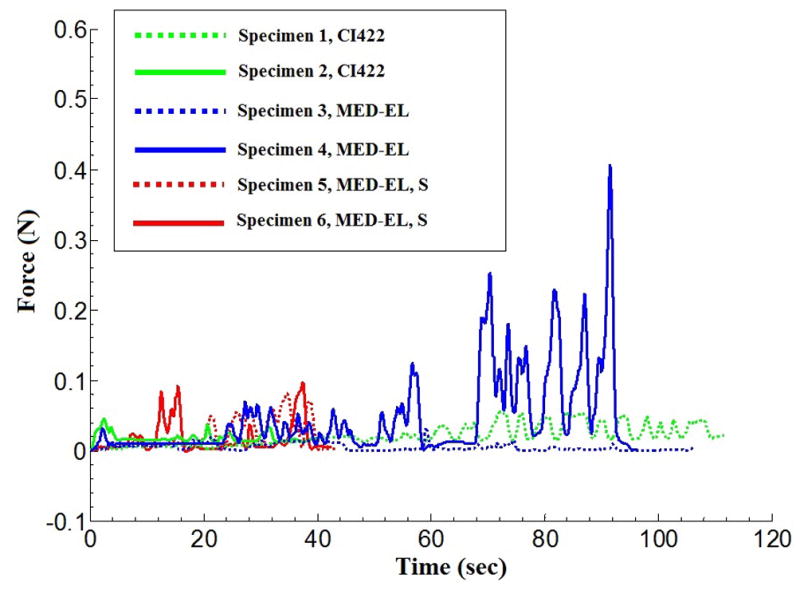
Insertion forces corresponding to the three electrode types.
The experimental setup records all forces acting on the temporal bone which may include forces applied by the insertion tool or the surgeon. The measured force data must be checked for consistency so that reported forces reflect only those applied by the implant onto the cochlea. The location of the cochlea with respect to the sensor was not known a priori. However, the location of force applied to the cochlea by the electrode was restricted to a relatively small volume and this information was used to detect outliers—forces not applied by the electrode. Assuming that the insertion of the electrode, with a highly flexible structure, does not impart significant moments about the x, y, or z axes, the sensed force and moment data can be used to determine the average location of contact in the force sensor frame. Expected moment can then be calculated. Any significant difference between the expected and measured moment, referred to by residual moment, mresidual, indicates periods of time when other forces may be acting on the bone. For example, significant contact between the surgical forceps and the specimen can be identified by this method. The moment sensor has a resolution of 0.1 N-m (merror). If mresidual was larger than merror, a correction factor, or weight, ranging between 0 and 1 was applied to the corresponding force measurement. The weight (w) is defined as:
In this equation, when α is set to 0.35, the assigned weight to a particular force would be half the original value since the residual moment outcome is twice the magnitude of the expected error. In effect, value of α determines how quickly confidence is lost in that a particular measured force corresponded purely to electrode insertion.
Average, weighted average, and peak forces corresponding to histological outcomes noted in each specimen are presented in Table 1. While unweighted averages for each insertion include all force data points, weighted averages correct for outlier data as described above. Of note, reported peak forces do not include data points corrected by the weighting formula above.
Table 1.
Force and histology outcomes summary.
| Specimen | Electrode | Average Force (N) | Weighted Average Force(N) | Peak Force (N) | Insertion Angle | Location |
|---|---|---|---|---|---|---|
| 1 | Cochlear 422 | 0.023 | 0.022 | 0.056 | 360° | ST |
| 2 | Cochlear 422 | 0.043 | 0.043 | 0.067 | 360° | ST |
| 3 | MED-EL | 0.009 | 0.008 | 0.061 | 450° | ST |
| 4 | MED-EL | 0.078 | 0.053 | 0.469 | 600° | SV |
| 5 | MED-EL, S | 0.023 | 0.023 | 0.084 | 540° | ST |
| 6 | MED-EL, S | 0.020 | 0.020 | 0.105 | 450° | ST |
ST: Scala Tympani, SV: Scala Vestibuli
Discussion
Using the minimally-invasive, image-guided surgical approach, we successfully gained access to the cochlea and inserted electrodes in 6 out of 6 specimens with minimal trauma. Five of the 6 specimens were inserted fully in ST and 1 of the 6 inserted fully in SV. The only visible trauma was a micro-defect on the lower side of the osseous spiral lamina which did not traverse the thickness of the spiral lamina in the first Nucleus CI422 insertion. Regarding the insertion in SV, comparison of the planned path with the actual drilled path as identified on the post-insertion CT showed a minor deviation of the drilled path from the planned trajectory during the drilling process, resulting in the targeting of the SV. Possible explanations for this targeting error include: 1) Error in localizing the location of the fiducial markers due to poor image quality of the flat panel cone beam CT scanner used for this study14, 2) Error in assembling the microstereotactic frame, and/or 3) Deviation by the drill bit on contact with the bone. Based on our prior studies3–7, we believe poor image quality or unstable microstereotactic frame assembly were unlikely causes of deviation. A closer look at the CT scan of the specimen reveals the presence of a large air cell measuring approximately 6 × 10 × 13 mm3 within which the 3.8 mm drill was set to stop (Figure 8). Following the switch to the 1.6 mm drill bit, advancement and eventual contact with the bone could have potentially caused the bit to deviate and follow a slightly different path, even despite the use of a bushing to constrain movement. The ultimate drilled path was away from the facial nerve and did not cause damage to it.
Figure 8.
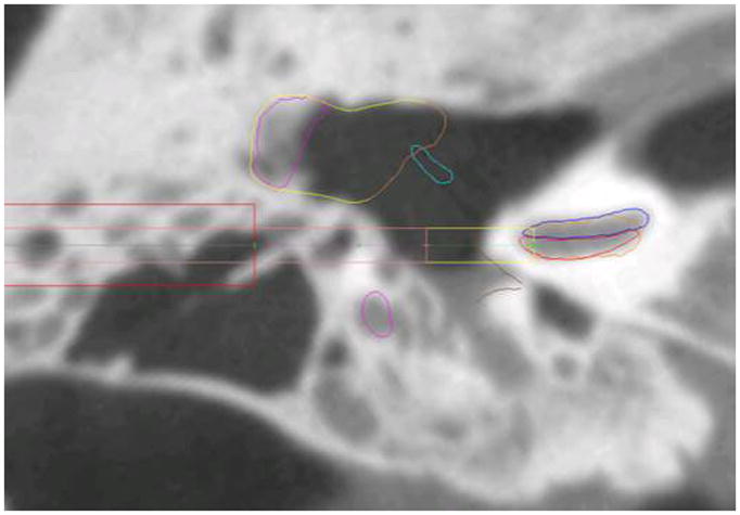
CT scan of Specimen 4. The large air cell present during the transition from the wide to thin drill bit may have caused the thin drill bit to deviate on hitting the hard bone surface.
In both temporal bone models and clinical reports, intracochlear trauma secondary to CI is relatively common occurring clinically in as many as one third of CI insertions15. The minimally-invasive, image-guided approach does provide an optimal insertion angle specified as that angle which allows a 10mm long cylinder to be placed into the basal turn of the ST. The drilled tunnel directs insertion forces coaxial with this insertion angle and, theoretically, results in less intracochlear trauma. While this less trauma effect was noted in the current study, we also note that for those cases in which resistance was met prior to complete insertion, buckling of the electrode array in the basal turn was noted and can be seen in the post-insertion CT scans of specimens 3 and 6.
The electrode array with the smallest diameter, the Nucleus CI422, was completely inserted, i.e. all electrodes intracochlear, in both cases to a depth of 360°. While the standard MED-EL arrays had deeper insertions ranging from 450 – 600°, because of their geometry incomplete insertion was achieved with only 10–11 of the 12 electrodes intracochlear. The MED-EL custom electrodes with stiffeners were developed specifically for this surgical approach to allow use of the stiffened transmitting wire (from the internal receiver to the electrode array) as an insertion tool that the surgeon could grasp and insert without the use of additional instruments. While this modified electrode worked as designed, the depth of insertion was not dramatically different than that of the standard MED-EL electrodes without the stiffeners.
Peak insertion forces, with the exception of the SV placement in Specimen 4, were at or below 105 milliN with an average force of approximately 30 milliN across the studied electrodes. Previous studies of forces associated with electrode insertions in the setting of traditional CI have varied greatly from less than 5 milliN to 200 milliN using both lateral wall and perimodiolar electrodes. Insertions were performed in either bone samples or cochlear models. A summary of the most relevant studies is included as Table 216–20. The average forces obtained in the current study are comparable with the range of those previously reported.
Table 2.
Previously published average forces of insertion in traditional cochlear implantation.
| Lead Author | Average Force (N) | Electrode | Target |
|---|---|---|---|
| Roland16 | 0.15 – 0.2 (SIT) < 0.05 (AOS) |
Cochlear, NCA (PM) | Temporal bone |
| Schurzig17 | 0.046 ± 0.027 | Cochlear, Freedom (PM) | Cochlear model |
| Majdani18 | 0.004 ± 0.001 | Cochlear, NCA (PM) | Cochlear model |
| Miroir19 | <0.20 | Advanced Bionics, 1J (LW) | Temporal bone |
| Pile20 | <0.14 | Cochlear, NCA (PM) | Temporal bone |
SIT: Standard Insertion Technique; AOS: Advance Off Stylet; NCA: Nucleus Contour Advance; PM: Perimodiolar electrode; LW: Lateral Wall electrode
Conclusion
We presented the force and trauma associated with the insertion of electrode arrays via the minimally-invasive, image-guided CI approach, which involves inserting an electrode array via a narrow linear tunnel drilled from the lateral skull to the cochlea. We have shown on six cadaveric temporal bone specimens that deep insertion was possible without crossover and without identifiable trauma using three different lateral wall electrodes. The average insertion forces measured in our study were comparable to the reported average insertion forces for traditional CI approach.
Acknowledgments
Research reported in this project was supported by NIH/NIDCD awards #R01DC008408 and R01DC10184 and NIH/NCATS award #UL1 TR000445. The content is solely the responsibility of the authors and does not necessarily represent the views of the National Institutes of Health. The authors would like to sincerely thank C. Gary Wright, PhD and Louis Kratchman, BS for their contributions to and support for this work.
Footnotes
Conference presentation:
The data contained in this manuscript was presented at the 2013 AAO-HNSF Annual Meeting, Vancouver, BC—Scientific Oral Presentations: Otology/Neurotology Session.
Contributor Information
Pooyan Rohani, Vanderbilt University School of Medicine, Nashville, TN, USA.
Jason Pile, Department of Mechanical Engineering, Vanderbilt University, Nashville, TN, USA.
Lueder A Kahrs, Institute of Mechatronic Systems, Leibniz University Hannover, Hannover, Germany).
Ramya Balachandran, Department of Otolaryngology-Head and Neck Surgery, Vanderbilt University Medical Center, Nashville, TN, USA.
Grégoire S Blachon, Department of Otolaryngology-Head and Neck Surgery, Vanderbilt University Medical Center, Nashville, TN, USA.
Nabil Simaan, Department of Mechanical Engineering, Vanderbilt University, Nashville, TN, USA.
Robert F Labadie, Department of Otolaryngology-Head and Neck Surgery, Vanderbilt University Medical Center, Nashville, TN, USA.
References
- 1.Kronenberg J, Migirov L, Dagan T. Suprameatal approach: new surgical approach for cochlear implantation. J Laryngol Otol. 2001;115(4):283–285. doi: 10.1258/0022215011907451. [DOI] [PubMed] [Google Scholar]
- 2.Kronenberg J, Baumgartner W, Migirov L, Dagan T, Hildesheimer M. The suprameatal approach: an alternative surgical approach to cochlear implantation. Otol Neurotol. 2004;25(1):41–44. doi: 10.1097/00129492-200401000-00008. discussion 44–45. [DOI] [PubMed] [Google Scholar]
- 3.Balachandran R, Mitchell JE, Blachon G, et al. Percutaneous cochlear implant drilling via customized frames: an in vitro study. Otolaryngol Head Neck Surg. 2010;142(3):421–426. doi: 10.1016/j.otohns.2009.11.029. [DOI] [PMC free article] [PubMed] [Google Scholar]
- 4.Warren FM, Balachandran R, Fitzpatrick JM, Labadie RF. Percutaneous cochlear access using bone-mounted, customized drill guides: demonstration of concept in vitro. Otol Neurotol. 2007;28(3):325–329. doi: 10.1097/01.mao.0000253287.86737.2e. [DOI] [PubMed] [Google Scholar]
- 5.Labadie RF, Mitchell J, Balachandran R, Fitzpatrick JM. Customized, rapid-production microstereotactic table for surgical targeting: description of concept and in vitro validation. Int J Comput Assist Radiol Surg. 2009;4(3):273–280. doi: 10.1007/s11548-009-0292-3. [DOI] [PMC free article] [PubMed] [Google Scholar]
- 6.Labadie RF, Noble JH, Dawant BM, Balachandran R, Majdani O, Fitzpatrick JM. Clinical validation of percutaneous cochlear implant surgery: initial report. Laryngoscope. 2008;118(6):1031–1039. doi: 10.1097/MLG.0b013e31816b309e. [DOI] [PMC free article] [PubMed] [Google Scholar]
- 7.Labadie RF, Balachandran R, Mitchell JE, et al. Clinical validation study of percutaneous cochlear access using patient-customized microstereotactic frames. Otol Neurotol. 2010;31(1):94–99. doi: 10.1097/MAO.0b013e3181c2f81a. [DOI] [PMC free article] [PubMed] [Google Scholar]
- 8.Noble JH, Warren FM, Labadie RF, Dawant BM. Automatic segmentation of the facial nerve and chorda tympani in CT images using spatially dependent feature values. Med Phys. 2008;35(12):5375–5384. doi: 10.1118/1.3005479. [DOI] [PMC free article] [PubMed] [Google Scholar]
- 9.Noble JH, Dawant BM, Warren FM, Labadie RF. Automatic Identification and 3D Rendering of Temporal Bone Anatomy. Otology & Neurotology. 2009;30(4):436–442. doi: 10.1097/MAO.0b013e31819e61ed. [DOI] [PMC free article] [PubMed] [Google Scholar]
- 10.Noble JH, Majdani O, Labadie RF, Dawant B, Fitzpatrick JM. Automatic determination of optimal linear drilling trajectories for cochlear access accounting for drill-positioning error. Int J Med Robot. 2010;6(3):281–290. doi: 10.1002/rcs.330. [DOI] [PMC free article] [PubMed] [Google Scholar]
- 11.Kratchman LB, Schurzig D, McRackan TR, et al. A manually operated, advance off-stylet insertion tool for minimally invasive cochlear implantation surgery. IEEE Trans Biomed Eng. 2012;59(10):2792–2800. doi: 10.1109/TBME.2012.2210220. [DOI] [PMC free article] [PubMed] [Google Scholar]
- 12.McRackan TR, Balachandran R, Blachon GS, et al. Validation of minimally invasive, image-guided cochlear implantation using Advanced Bionics, Cochlear, and Medel electrodes in a cadaver model. International Journal of Computer Assisted Radiology and Surgery. 2013 doi: 10.1007/s11548-013-0842-6. [DOI] [PMC free article] [PubMed] [Google Scholar]
- 13.Wright CG, Roland PS. Temporal bone microdissection for anatomic study of cochlear implant electrodes. Cochlear Implants Int. 2005;6(4):159–168. doi: 10.1002/cii.11. [DOI] [PubMed] [Google Scholar]
- 14.Balachandran R, Schurzig D, Fitzpatrick JM, Labadie RF. Evaluation of portable CT scanners for otologic image-guided surgery. Int J Comput Assist Radiol Surg. 2012;7(2):315–321. doi: 10.1007/s11548-011-0639-4. [DOI] [PMC free article] [PubMed] [Google Scholar]
- 15.Wanna GB, Noble JH, McRackan TR, et al. Assessment of electrode placement and audiological outcomes in bilateral cochlear implantation. Otol Neurotol. 2011;32(3):428–432. doi: 10.1097/MAO.0b013e3182096dc2. [DOI] [PMC free article] [PubMed] [Google Scholar]
- 16.Roland JT., Jr A model for cochlear implant electrode insertion and force evaluation: results with a new electrode design and insertion technique. Laryngoscope. 2005;115(8):1325–1339. doi: 10.1097/01.mlg.0000167993.05007.35. [DOI] [PubMed] [Google Scholar]
- 17.Schurzig D, Webster RJ, 3rd, Dietrich MS, Labadie RF. Force of cochlear implant electrode insertion performed by a robotic insertion tool: comparison of traditional versus Advance Off-Stylet techniques. Otol Neurotol. 2010;31(8):1207–1210. doi: 10.1097/MAO.0b013e3181f2ebc3. [DOI] [PMC free article] [PubMed] [Google Scholar]
- 18.Majdani O, Schurzig D, Hussong A, et al. Force measurement of insertion of cochlear implant electrode arrays in vitro: comparison of surgeon to automated insertion tool. Acta Otolaryngol. 2010;130(1):31–36. doi: 10.3109/00016480902998281. [DOI] [PMC free article] [PubMed] [Google Scholar]
- 19.Miroir M, Nguyen Y, Kazmitcheff G, Ferrary E, Sterkers O, Grayeli AB. Friction force measurement during cochlear implant insertion: application to a force-controlled insertion tool design. Otol Neurotol. 2012;33(6):1092–1100. doi: 10.1097/MAO.0b013e31825f24de. [DOI] [PubMed] [Google Scholar]
- 20.Pile J, Simaan N. Characterization of Friction and Speed Effects and Methods for Detection of Cochlear Implant Electrode Tip Fold-over. IEEE International Conference on Robotics and Automation; 2013. [Google Scholar]


