

Abstract
Current designs for microelectrodes used for interfacing with the nervous system elicit a characteristic inflammatory response that leads to scar tissue encapsulation, electrical insulation of the electrode from the tissue and ultimately failure. Traditionally, relatively stiff materials like tungsten and silicon are employed which have mechanical properties several orders of magnitude different from neural tissue. This mechanical mismatch is thought to be a major cause of chronic inflammation and degeneration around the device. In an effort to minimize the disparity between neural interface devices and the brain, novel soft electrodes consisting of elastomers and intrinsically conducting polymers were fabricated. The physical, mechanical and electrochemical properties of these materials were extensively characterized to identify the formulations with the optimal combination of parameters including Young’s modulus, elongation at break, ultimate tensile strength, conductivity, impedance and surface charge injection. Our final electrode has a Young’s modulus of 974 kPa which is five orders of magnitude lower than tungsten and significantly lower than other polymer-based neural electrode materials. In vitro cell culture experiments demonstrated the favorable interaction between these soft materials and neurons, astrocytes and microglia, with higher neuronal attachment and a two-fold reduction in inflammatory microglia attachment on soft devices compared to stiff controls. Surface immobilization of neuronal adhesion proteins on these microwires further improved the cellular response. Finally, in vivo electrophysiology demonstrated the functionality of the elastomeric electrodes in recording single unit activity in the rodent visual cortex. The results presented provide initial evidence in support of the use of soft materials in neural interface applications.
Keywords: conducting elastomer, neural interface, composite bio-electrodes, soft electrodes
Introduction
Neural interfacing devices, particularly intracortical microelectrodes, are able to record neuronal activity from individual or small populations of neurons [1–3]. These devices are not only valuable research tools for studying brain functions but have tremendous clinical potential for restoring neural functions and/or treating neurological disorders. However, widespread application of these technologies is hindered as a result of the high degree of variability and poor long-term performance. For example, in the monkey cortex, studies have reported a 40–60% chance of being able to record activity after implantation [2], a 40% drop in the number of functional electrodes between 1 and 18 months [4], and average declines in action potential amplitude of 2.4% per month [5]. Similar inconsistency has been observed in rodents [6, 7] with performance variability observed across arrays, animal models and even electrodes in the same array [8–11]. Regardless of the electrode used [12], dynamic cellular responses at the electrode-tissue interface pose a challenge to chronically implanted microelectrodes thereby hindering the clinical translation of cortical neural prosthetic devices.
Device implantation causes a wide range of alterations in all of the constituent cell types, disrupts the blood-brain barrier and initiates a cascade of both acute and chronic host tissue reactions (reviewed in [13–16]). Recruitment of macrophages and activation of microglia occurs immediately, initiated by the trauma associated with implantation [17]; these cells begin to encapsulate the implant minutes after insertion, migrating to the device surface as early as one day post-implantation and remaining there for as long as the implant remains in contact with brain tissue [14, 18]. Astrocyte activation produces a reactive phenotype characterized by enhanced migration, proliferation, hypertrophy, up-regulation of glial fibrillary acidic protein (GFAP) and increased matrix production [19–22]. Over approximately 1–4 months, astrocytes and microglia form a tight, non-conducting sheath that encapsulates and insulates the electrode from nearby neurons and increases impedance at the electrode-tissue interface [20, 23]. This astrocytic scar may direct neuronal processes away from foreign/“non-brain” structures [24–27] and has been suggested as the primary mechanism for decreasing recording capability over time [15]. Insertion injury, mechanical irritation and chronic inflammation due to a sustained foreign body response [28, 29] also contribute to decreased neuronal density and retraction of neuronal processes [30]. In addition, the release of chemokines (i.e., MCP-1) and cytokines (i.e., TNFα and IL-1β) results in local neurotoxicity even when these signaling molecules have anti-inflammatory properties [31]. Furthermore, damage to the blood-brain barrier (BBB) can result in the accumulation of neurotoxic factors which negatively affects neuronal health and electrode performance [29, 32–36]. This loss of viable neurons at the electrode-tissue interface may contribute to signal deterioration and the eventual failure of penetrating electrodes. Therefore, to improve the long-term reliability of neural probe over time, the next generation of high-performance microelectrodes must cause a lower tissue reactivity, BBB disruption, glial response and neuronal degeneration/damage [27, 35, 37]. It is also critical to consider electrode design factors including size, shape and tethering [35, 38, 39].
A widely-accepted principle in the field of biomaterials is that the mechanical properties of an implant should match those of the host tissue to reduce the inflammatory response and foreign body reaction. However, current neural probes are made with very stiff materials [i.e., material with a high Young’s modulus (E)] like tungsten (E = 400 GPa), silicon (E = 200 GPa), polyimide (E = 3 GPa) or Parylene C (E = 2–5 GPa). Consequently, the Young’s modulus of materials used for the most common microelectrodes is several orders of magnitude greater than that of brain tissue (E = 0.4–15 kPa, [40–43]). This enormous mismatch can significantly augment the foreign body response with “frustrated phagocytosis” [15, 44] as well as the inflammatory response associated with friction-induced stress under micromotion [20, 45–47]. In addition, increased mechanical strain has been shown to up-regulate IL-1β [44], which has an antagonistic effect on the recording performance of chronically-implanted intracortical electrodes [29]. In this way, the mechanical properties of implants affect cellular structure, metabolism, motility, transcription/translation and viability [43, 48] impacting the glial scar, neuronal health and the overall cellular response at the electrode-tissue interface [15, 18, 26, 49]. Furthermore, stiff implants that include subcomponents with large mechanical mismatch within the device have exhibited material failure induced by mechanical strain [50].
Soft (low modulus) materials are thought to cause less micromotion-induced damage because of their shock absorption and vibration dampening properties; finite element modeling revealed that softer substrates reduce the strain at the electrode–tissue interface [45] and physical coupling of electrodes and the brain reduces micromotion-induced strain [51]. Indeed, significant efforts have been aimed at addressing the mechanical disparity between neural tissue and implantable neural electrodes. Microelectrode substrates and coatings using more compliant materials have been investigated [52–59] as have mechanically-adaptive materials [60, 61] among other strategies. The histology studies showed improved tissue responses, but the functional recording performance from these novel materials has yet to be demonstrated. Here we report on the fabrication and in vitro testing of novel functional soft electrodes with Young’s modulus of 974 kPa, more than three orders of magnitude lower than polyimide and five orders of magnitude lower than tungsten, and significantly lower than other soft neural electrode materials reported in the literature (15 MPa in [60] and 5 MPa in [61]). The novel soft electrodes are microwires with an inner conducting core made of a novel blend of silicone and an intrinsically conducting polymer (ICP) and an outer insulating layer made of fluorosilicone. Among ICPs, poly(3,4-ethylenedioxythiophene) (PEDOT) has been shown to have high biocompatibility, acceptable in vivo stability and high surface charge capacity [62, 63] and was used for the fabrication of the conducting core of our soft wires. We used a form of PEDOT (a perchlorate-doped lauryl-terminated PEDOT-polyethylene glycol (PEG) triblock-copolymer) that, because of its tri-block copolymer structure, can be easily mixed with hydrophobic materials such as silicones and forms homogeneous, highly conducting silicone-PEDOT blends.
Our novel soft wires demonstrated excellent biocompatibility, high surface charge capacity and a large electrochemical surface area. In vitro testing demonstrated the ability to support neuron attachment and growth better than traditional stiff microelectrodes and with reduced attachment of microglia. The outer insulating layer was also amenable to biomolecule coatings which further promoted neuronal attachment and neurite outgrowth in vitro. Acute in vivo recording experiments suggest that these soft electrodes are capable of recording single unit neural activity when implanted into the rodent brain.
Experimental
Soft wire fabrication materials
Aedotron™ C3 (TDA Research, Inc., Wheat Ridge, CO) is a perchlorate-doped lauryl-terminated PEDOT-PEG triblock-copolymer (C12-PEG-PEDOT-PEG-C12, Figure 1) supplied as a gel in acetonitrile (ACN) [64]. The bulk conductivity of the batch of Aedotron™ C3 used in this study was 27 S/cm, as determined by four-point measurements on dry pressed pellets of the material. Aedotron™ C3gel can be used to form blends with a variety of hydrophobic polymers, including silicones. The commercial medical grade silicone MED6607 and fluorosilicone MED6655 (Nusil Technologies, Inc., Carpinteria, CA) were used as received or diluted with hexane or n-butyl-acetate as necessary. All solvents, reagents, and processing additives were purchased at or above reagent-grade quality and used as received.
Figure 1.
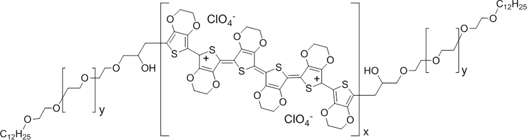
Chemical structure of bis[lauryl-terminated poly(ethylene glycol)-co-poly(3,4-ethylenedioxythiophene)] (c12-peg-pedot-peg-c12, aedotron™ c3, tda research, inc.). the central pedot chain is perchlorate-doped and serves as the primary source of conductivity in the soft electrodes.
Formulation and extrusion of Silicone/Aedotron™ C3 blends to form elastic conducting wires
Blends of MED6607 and Aedotron™ C3 at loadings from 4.5%-15% wt. (as weight of solid filler over total dry formula weight) were prepared by mixing Aedotron™ C3 gel with the naptha-silicone dispersion at the chosen ratio, calculating for the final dry blend compositions. The mixture was blended in a centrifugal mixer (Flacktek SpeedMixer DAC 600, Landrum, SC) and a fraction of the solvent was allowed to evaporate at ambient pressure until the mixture reached the optimal viscosity (as empirically evaluated by its flow through a syringe needle) for extrusion (typically 12–16h).
Flat specimens were prepared by knifing the viscous blend into a mold or by sandwiching it between two flat surfaces followed by curing under ambient conditions for ≥18 hours. Cured specimens were cut into rectangular strips or other monolithic shapes for mechanical testing. Alternatively, cylindrical specimens (wires) were made by extruding the viscous blend with a syringe through a trimmed and polished needle bore (22G–30G) and the extruded wire was allowed to cure completely before testing or further fabrication steps.
Subsets of fully cured wire samples were coated with an insulating layer of fluorosilicone (FS, unfilled Nusil MED6655) or Parylene C. FS coatings were applied by dip-coating the conducting wires in an uncured solution of MED6655. The MED6655 dip coating solution was prepared by diluting one part MED6655 in two parts n-butyl-acetate by weight. Three coats were used for the FS-coated wires (MED6655). Parylene C coatings were applied by vapor deposition at room temperature at Vertical Solutions, Inc. (Louisville, CO). Typical coating thickness was determined by imaging and found to be 5 ± 2 µm for FS and 3 µm for Parylene C. Coated wires were trimmed at both ends to expose the conducting core. For FS-coated wires, manual trimming was performed orthogonal to the wire axis using a razor blade. Parylene C-coated wires were first encased in a UV-curing optical adhesive (#68 Norland Optical Adhesive, Edmund Optics) to prevent pinching of the insulating shell during trimming; this adhesive embedding was later removed by soaking in a 4:1 (vol:vol) mixture of dichloromethane:1-methyl-2-pyrrolidinone.
A detailed description of the fabrication of the soft wires for in vivo studies can be found in the Supplementary Material.
Characterization of coated and uncoated wires
Images of both coated and uncoated wires were acquired using field-emission scanning electron microscopy (FE-SEM; JEOL model JSM-7000F FE-SEM) and with an optical microscope (Bausch & Lomb MicroZoom® II, with a Moticam 350 USB digital capture camera). The linear resistance of uncoated wires was measured at four random lengths (ranging from ca. 4–24 mm) and averaged for a given sample; silver paint was used to establish the linear resistance contacts (SPI, High Purity silver paint). The bulk conductivity of the uncoated wires was then calculated from the linear resistance as described in the Supplementary Material. The ability of the coating to provide a continuous insulating shell was probed in air using silver paint contacts and in phosphate buffered saline (PBS) by measuring the resistance between the cut wire ends and between random locations along the insulated wire and the end.
Mechanical properties were tested in tension with an Instron Mechanical tester equipped with a 20-pound load cell at room temperature following a modified ASTM D 412 procedure (Tensile Strength Properties of Rubber and Elastomers). Specimens used for testing were either rectangular prisms cut from the flat films or cylinders cut from the extruded wires. Rectangular prisms had dimensions in the following ranges: L = 13–25 mm, W = 0.5–1 mm, T = 0.2–0.6 mm. Cylinders had lengths of 25–113 mm and cross-sectional areas from 0.01–0.04 mm2. Specimens were mounted within the instrument grips with an established initial gauge length (12.7 or 25.4 mm) and elongated at a rate of 10.16 mm/min until failure. Elongation versus load was recorded. Curves of stress (load/cross sectional area) versus strain (% elongation) were plotted to calculate the Young’s Modulus (which is the slope of the tangent to the linear portion of the curve near zero elongation), elongation at break and the ultimate tensile strength. Results reported were averages of 2–5 measurements.
Modification via protein adsorption
A two-step approach described previously was used to coat wires with bioactive proteins known to promote neuronal adhesion (laminin or L1) [65, 66]. Briefly, soft wires were exposed to air or oxygen plasma (30 W) for 10 seconds (Harrick Plasma, PDC-001) and then incubated in protein solutions for 1 hour at 4°C. Untreated, plasma-treated and plasma-treated + protein adsorption groups for the soft wires were compared to untreated and plasma-treated stiff wires. Laminin (Sigma-Aldrich, St. Louis, MO) was used at a concentration of 40 µg/mL. L1 was prepared via affinity purification of murine brain tissue as described previously [66, 67] and used at a concentration of 50–100 µg/mL as determined by the BCA Protein Assay Kit (Thermo Fisher Scientific, Pittsburgh, PA).
Cell culture
Primary neuronal cultures were established from rat cortices from embryonic day 18 (E18) Sprague-Dawley rats. Cells were resuspended in neurobasal base media (Invitrogen, Carlsbad, CA) supplemented with B27 (Invitrogen), glutamine (Sigma-Aldrich) and glutamate (Sigma-Aldrich). Neurons were plated at a density of 500 cells/mm2 and maintained in culture for 2 days at 37°C and 5% CO2 prior to fixation.
Astrocyte-enriched cultures were prepared as described previously [68]. Briefly, rat cortices were digested with trypsin and the resulting cell suspension maintained in DMEM (Invitrogen) supplemented with 10% fetal bovine serum (FBS; Thermo Fisher Scientific) at 37°C and 5% CO2. For surface modification experiments, glial cells were passaged after 2 weeks in culture and plated at a density of 500 cells/mm2. Astrocytes were subsequently cultured for 7 days prior to fixation.
Highly Aggressively Proliferating Immortalized (HAPI) cells [69] were kindly provided by Dr. Xiaoming Hu, Department of Neurology, University of Pittsburgh and cultured as described previously [70]. Briefly, HAPI cells were maintained in DMEM/F12 lacking HEPES and Phenol Red (Invitrogen) supplemented with L-glutamine (Sigma-Aldrich) and 10% FBS (Thermo Fisher Scientific). After thawing, cells were passaged two-three times prior to plating at a density of 500 cells/mm2 and incubated for 72 hours at 37°C and 5% CO2 before fixation.
For all cell culture experiments, wires were fixed to the bottom of the cell culture plate on one end only with Kwik-Sil to mimic micromotion-induced forces. Once attached, cells were plated at the densities detailed above.
Immunofluorescence
At the designated time points, cells were fixed with 4% paraformaldehyde (PFA; Sigma-Aldrich) for 10 minutes. After blocking for 45 minutes with 10% goat serum in PBS, primary antibodies were added for 1 hour at room temperature. Monoclonal antibodies were used to detect neuronal class III β-tubulin (Invitrogen), glial fibrillary acidic protein (GFAP; DakoCytomation, Carpinteria, CA) and ED1 (AbD Serotec, Raleigh, NC). These antibodies were used at a dilution of 1:500 (β3-tubulin, GFAP) or 1:250 (ED1). After washing, the appropriate fluorescence-conjugated antibody used at a dilution of 1:500 was added for 1 hour. Cell nuclei were counterstained with Hoechst 33258 (2 µg/mL; Sigma-Aldrich) in PBS. Three samples for each condition were used for each experiment and experiments were repeated at least three times.
Digital images of the stained cells were taken using a fluorescence microscope (FluoView 1000, Olympus, Inc., Tokyo, Japan). Neuronal attachment was determined by counting the number of neurons that showed co-localization of neuronal class III β-tubulin and Hoescht. Astrocyte attachment was determined for cells that showed co-localization of GFAP and Hoescht. Microglia attachment was determined by the co-localization of ED1 and Hoescht. The entire probe was imaged and all cells on the surface of the probes were counted by a non-objective examiner. The cell number was reported by dividing the total number of cells by the projected surface area (2.54 cm2 for control wires, 1.76 cm2 for Parylene C soft wires, 1.52 cm2 for fluorosilicone soft wires). Each treatment group included three replicates and experiments were repeated at least three times.
Electrochemical characterization
Cyclic voltammetry (CV) was carried out on a Pine Instrument Company bipotentiostat model AFC BP1 (Grove City, PA) in a three-electrode cell using a platinum wire counter electrode, Ag/AgCl reference electrode (0.197 V vs. NHE), PBS electrolyte, and an immersed soft wire sample as the working electrode. The stable electrochemical potential window was found to be −0.5 to +1.0 V (vs. Ag/AgCl) and the CVs were recorded over this range at 50 mV/s and 1,000 mV/s. The cathodic, anodic, and total surface charge capacity was measured by integration of the CV current traces with time. The electrochemical impedance spectra (EIS) were measured on a G300 Gamry AC Impedance Analyzer (Gamry Instruments, Warminster, PA) using the same three-electrode cell described above.
In Vivo Functional Analysis
All surgical procedures were done in accordance with those outlined by the United States Department of Agriculture and approved by the Institutional Animal Care and Use Committee of the University of Pittsburgh. Animals were housed in the facilities of the University of Pittsburgh, Division of Laboratory Animal Resources and given free access to food and water.
Adult male Sprague-Dawley rats (Charles River Laboratories, Malvern, PA) weighing 300–350 g were prepared for cortical implants as described previously [71]. Animals were anesthetized with 5% isofluorane in oxygen at 1 L/min. After induction, isofluorane was reduced to 2% and then gradually reduced by 0.125% every 30–60 min. for the duration of the procedure. Anesthesia level was closely monitored by observing changes in respiratory rate, heart rate, body temperature (37.7°C) and absence of the pedal reflex. Animal temperature was maintained throughout the procedure using a warm water pad (HTP 1500, Adroit Medical Systems, Loudon, TN).
Rats were placed in a stereotaxic frame (SR-6R-HT, Narishige, Japan) and the hair over the incision site removed. The skin was disinfected with isopropyl alcohol and betadine and a sterile environment maintained throughout the procedure. The top surface of the skull was exposed and a 3 mm by 3 mm craniotomy made over the primary visual cortex using a manual hand drill. Saline was applied onto the skull continuously to dissipate heat from the high-speed drill. Extra care was taken to prevent damage to the dura by gently feeling the resistance of the skull when the dural blood vessels were visible through the thin skull. The dura was incised and resected. Sterile saline was used to keep the brain surface moist throughout the procedure.
A total of three bone screws were installed bilaterally over the primary motor cortex as well as over the contralateral visual cortex. The reference wire was connected to the bone screw over the contralateral visual cortex while the ground wire was connected to both bone screws over the motor cortex. The electrodes were placed over the visual cortex and lowered to the surface of the brain in a region where major arteries and veins were >>50 µm away as previously described [33]. The electrode was lowered 1.2 mm and allowed to bend. The soft wire electrode was gently advanced into the brain manually with Teflon-coated forceps until the slack on the soft wire was eliminated. Extra care was taken not to damage the insulation during manipulation.
Neural electrophysiology was recorded as previously described using the RX5 (Tucker-Davis Technologies, Alachua, FL) [72]. Spontaneous recording was conducted in a dark room. Visual stimuli were presented using the MATLAB-based Psychophysics Toolbox [73–75] on a 24 inch LCD (V243H, Acer, Xizhi, New Taipei City, Taiwan) monitor placed 20 cm from the eye contralateral to the implant, spanning a visual field of 60° wide by 60° high as previously described [29, 50]. Solid black and white bar gratings were presented drifting in a perpendicular direction and recorded at 24,414 Hz. Each 1 second of grating presentation (rotated in 45° increments) was separated by a 1 second dark screen period and the entire set was repeated 8 times/recording.
Electrophysiology and Spike Sorting
Neural recording segments were analyzed offline to determine the number of neurons recorded, noise levels, and signal amplitudes using custom automated MATLAB (Mathworks Inc., MA) software as described elsewhere [72, 76]. As an overview, the wide-band recordings were filtered in software to isolate the spike data (300–5000 Hz) from the local field potential (LFP) data (1–300 Hz). The LFP power spectral density plots were created using a Hamming window for smoothing with a 32768-point fast Fourier transform (FFT). Low frequency activity in the range typically observed for LFPs was presented. To identify single- and multi-units, the threshold for the high-frequency data was established using a window set at 3.5 standard deviations below the mean of the data. For each peak exceeding the threshold window, timestamps were recorded and plotted as a raster plot. The amplitude of the noise voltage for each recording site in each recorded segment was calculated after all candidate waveforms had been removed. A 3-msec waveform was extracted from the data stream at each threshold crossing. To group isolated waveforms into a single neuronal unit, principal component analysis was then completed, and the resultant components were separated into individual clusters by using Fuzzy C-means clustering. Units with sufficiently clustered principal components were plotted, and the signal-to-noise ratio (SNR) was calculated as the peak-to-peak amplitude of the mean waveform of the cluster divided by two times the standard deviation of the remaining data stream after all waveforms had been removed.
Statistical Analyses
Statistical analyses were performed using GraphPad Prism 5 (GraphPad Software, Inc., La Jolla, CA). Comparisons involving multiple groups were accomplished using two-way analysis of variance (ANOVA) followed by Bonferroni post-hoc analysis. A p value ≤ 0.05 was considered statistically significant.
Results and Discussion
The long-term function of electrodes designed for neural engineering applications is limited, in part, by the tissue reaction elicited by these stiff materials. By eliminating the mismatch in Young’s modulus and reducing micromotion-induced friction, this study aimed to minimize the foreign body response associated with implanted electrodes. Electrically conductive and insulating materials with mechanical properties similar to those of the CNS were developed and used to fabricate elastomeric electrodes. The conducting elastomer core of these soft electrodes provides a path for neuronal signals to reach the recording or stimulation unit. Non-conducting elastomers insulate the shaft of the electrodes. In this way, single or a few neurons can be accessed or recorded at the electrode tip. Characterization of these novel soft electrodes was performed and included testing in an in vitro cell culture system and acute implantation in a rodent model. The goal was to improve upon current implantable electrodes by balancing a number of ideal properties including functionality, non-toxicity, ease of handling, mechanical properties (low Young’s modulus, high elongation at break, high ultimate tensile strength), surface characteristics (neuronal attachment, amenable to modification via protein adsorption), and electrochemical properties (stable cyclic voltammetry, minimum impedance, maximum charge injection).
Rationale for the selection of materials, fabrication of wires and imaging procedures
Conducting core
Previously, block copolymers of conductive PEDOT and flexible polymer like poly(ethylene glycol) (PEG) or poly(dimethylsiloxane) (PDMS) [77] were used to produce copolymers of various architectures and containing various dopants to make blends with medical grade elastomers (unpublished results). In our preliminary studies, blends of Aedotron™ C3, a lauryl terminated PEDOT-PEG copolymer [64] (Figure 1) with the medical grade silicone MED6607 (Nusil) produced the material with the highest electrical conductivity, lowest Young’s modulus and lowest cell toxicity (Luebben and Cui, unpublished results). Based on these results and in this work, the formulation of conducting elastomers was optimized to maximize bulk conductivity and minimize Young’s modulus by varying the ratio of Aedotron™ C3 to MED6607. Therefore, minimizing toxicity and Young’s modulus was balanced with maximizing conductivity for the microwire core.
Insulating shroud
In this study, Parylene C and FS insulating shrouds were evaluated. Parylene C is used as an insulating material on commercially-available electrodes and was chosen because of its good dielectric properties and to use as a control for surface chemistry. FS was used because it has a low modulus, is biocompatible and has better barrier properties than PDMS; it is also well-known as a dielectric material in biological applications. Both the Parylene C and FS are approved for long-term implantation in humans and are used to insulate the shaft of the electrodes. Both surfaces are also amenable to protein adsorption, a factor considered specifically for the insulation material because of the opportunity to impact the cellular response to implanted microwires with biomolecule coatings.
Fabrication
The fabrication of soft conducting wires of various diameters was accomplished by extrusion of uncured Aedotron™ C3/MED6607/solvent blends though various syringe needles with bore diameters ranging from 144–442 µm. A 25–35% shrinkage was observed during the curing process due to solvent evaporation which resulted in cured wires 93–285 µm in diameter (Supplemental Table 1). The large variability of cured wired diameter extruded from the same needle size is due to the variable amount of solvent in the blend during extrusion because of slight variations in the time and temperature the solvent was allowed to evaporate prior to extrusion. In general, the conducting soft wires had good handling characteristics up to 29G. Smaller wires had poor reproducibility and were difficult to handle. In light of this result and to minimize trauma during implantation, 29G wires (roughly 130 µm wires) were chosen as the optimal size for the in vivo experiments. In order to achieve high-resolution single unit recording, the wires were lined with gold along the shaft and trimmed at the tip to obtain sufficiently small active area (Supplemental Figure 1). No gold was in direct contact with tissue.
FE-SEM Imaging
FE-SEM imaging was carried out to assess the phase homogeneity of the cured blends and to evaluate the possible presence of defects in the insulating shroud. SEM images of 29G uncoated soft wires made with 8.5% wt. Aedotron™ C3 and 91.5% MED6607 show that the cross-sectional surface of the tip (Figure 2, A and B) is homogeneous and no significant phase separation can be seen between the Aedotron™ C3 conducting domains and the PDMS non-conducting domains even at high magnification (white arrows in Figure 2B). In contrast, the side walls of the wires show areas of significant charging indicating that a small amount of PDMS phase-separates upon extrusion of the materials and migrates to the surface of the wire during curing (Figure 2, B, C and D). This is normal and expected since PDMS has a lower surface tension than Aedotron™ C3. Bright spots are due to charging and indicate that the specimen is electrically insulating in some regions. Overall these images confirm that our PDMS-Aedotron™ C3 blends cure to form a highly homogenous conducting elastomer and no significant (internal) phase separation occurs during curing.
Figure 2.
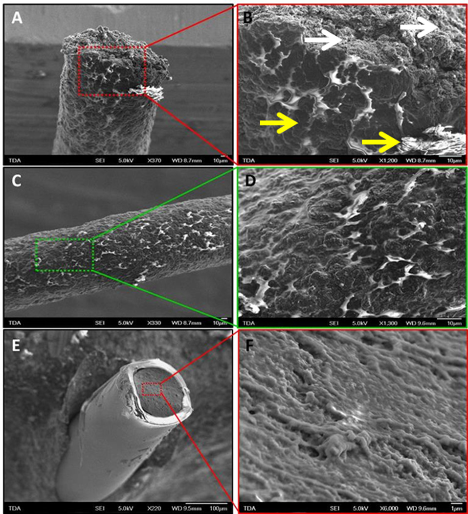
Fe-sem images of a 29g soft wire made with a blend of pdms (med6607 nusil technologies, 91.5% wt.) and c12-peg-pedot-pegc12 (aedotron™ c3, tda research, inc., 8.5% wt.). a, b, c and d are images of the as-extruded uncoated wire, while e and f are images of the fluorosilicone-coated wire. the section of the wire core (b and f) shows a relatively homogeneous distribution of the two materials in the blend and conducting and non-conducting domains cannot be distinguished even at 6000x resolution (f). in contrast, the sides of the extruded wire (c and d) shows lighter colored areas, which are due to electrically insulating domains that are charging in the electron beam. these domains are likely richer in pdms that preferentially phase separated at the wire surface during cure. the fluorosilicone coating (e) appears homogenous and defect-free. it is also bright because of charging in the electron beam. white arrows denote areas of homogeneity whereas yellow arrows indicate phase separation.
Figure 2E shows a FE-SEM image of a FS-coated wire that has been cut perpendicularly to the wire axis (i.e., not on a bias); the highly insulating FS shell also charges in the electron beam and appears bright. Importantly, the insulating shroud is uniform and defect free. The inner core of the wire (Figure 2F) appears darker because it is conducting and is electrically connected to the microscope sample stage. Again, the cross-sectional view of the core appears uniform without regional charging suggesting minimal phase separation. Overall these images confirm that the insulating coating is homogenous and free of defects.
Electrical properties of uncoated wires
The bulk conductivity of the soft wires as a function of the loading of conducting filler was calculated from linear resistance data (Figure 3 and Supplemental Table 2). As expected, the bulk conductivity increases with the amount of Aedotron™ C3 fill in the wires from 0.09 S/cm for the 4.5% loading to 6.3 S/cm for the 15% loading. The conductivity follows a typical percolation behavior (Figure 3); that is, in a mixture of dielectric and conductive components, conductivity changes over many orders of magnitude with small changes in concentration of the conducting component to approach the conductivity of the pure conducting component near the percolation threshold.
Figure 3.
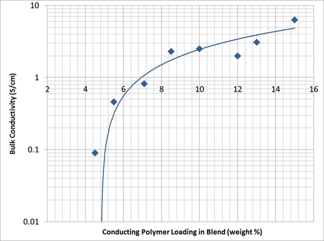
Bulk conductivity of 285 µm diameter wires (22g) versus the conducting polymer loading in pdms. a typical percolation behavior can be observed.
The linear resistance of these wires was measured as a function of wire diameter and Aedotron™ C3 loading; the linear resistance decreased as the amount of Aedotron™ C3 increased and as the wire’s diameter increased (data not shown). The lowest value was achieved with the 22G 15% filled wire (250 Ω/cm). However, as filler loading increased, the wires lost elasticity. Even at 10% loading, elastomers were too brittle to be handled (discussed in the next section). Therefore, the lowest range of linear resistance achieved with this class of materials was 650–700 Ohms/cm for the 8.5% filled 22G wires.
Mechanical properties of uncoated and insulated wires
The Young’s modulus (elastic modulus) was used as a representative physical quantity to compare the mechanical properties of the brain with those of the synthetic materials and was measured from the stress-strain curves of the elastomers’ specimens measured in tension (Table 1 for the unfilled elastomers and Table 2 for the conducting soft wires; typical stress-strain curves for unfilled PDMS and soft electrodes are provided in Supplemental Figure 2). Unfilled PDMS (MED6607) has a Young’s modulus of 42 kPa while unfilled FS (MED6655) is a softer material with Young’s modulus of 18.3 kPa (Table 1). The Young’s modulus of the PDMS/ Aedotron™ C3 blends increases with Aedotron™ C3 loading from 42 kPa of the unfilled material to 1.460 kPa of the 10% material (Table 2). The elongation at break simultaneously decreased from 650% for the unfilled PDMS to 5% for the 10% filled formula indicative of the material transition from a soft elastomer (with high elasticity) to a brittle compound (with very little elongation at break, Table 2). Notably, the change in ultimate strength is smaller, measured at 2.1 MPa for the unfilled material and 3.6 MPa for the 10% filled material. Both the Young’s modulus and elongation at break as a function of Aedotron™ C3 loading (%) undergo a transition in the range of 7–8% loading corresponding to the transition between a soft elastomer and a hard elastomer (Figure 4). Formulations with 8.5% Aedotron™ C3 loading provided the best combination of maximum conductivity (2.3 S/cm) and low modulus (800 kPa).
Table 1.
Mechanical properties of Nusil elastomers measured at room temperature with an Intron Mechanical Tester.
| Material | Young’s Modulus ± SD (kPa) |
Elongation at Break ± SD (%) |
Ultimate Tensile Strength ± SD (MPa) |
|---|---|---|---|
| PDMS (MED 6607) | 42 ± 8 | > 650 | 2.1 ± 0.4 |
| FS (MED 6655) | 18.3 ± 4.9 | 362 ± 100 | 7.3 ± 1.8 |
Table 2.
Mechanical properties of conducting elastomers measured on prismatic specimens or 22 G wires (285 µm in diameter) at room temperature with an Intron Mechanical Tester.
| Loading of Aedotron™ C3 in MED 6607 |
Young’s Modulus ± SD (kPa) |
Elongation at Break ± SD (%) |
Ultimate Tensile Strength ± SD (MPa) |
|---|---|---|---|
| 0% | 42 ± 8 | > 650 | 2.1 ± 0.4 |
| 4.5% | 109 ± 17 | > 350 | |
| 5.5% | 131 | 260 | |
| 7.1% | 210 ± 24 | 123 ± 17 | 2.3 ± 0.3 |
| 8.5% | 894 ± 34 | 24 ± 5 | 3.3 ± 0.2 |
| 10% | 1460 ± 250 | 5.5 ± 1 | 3.6 ± 0.3 |
Figure 4.
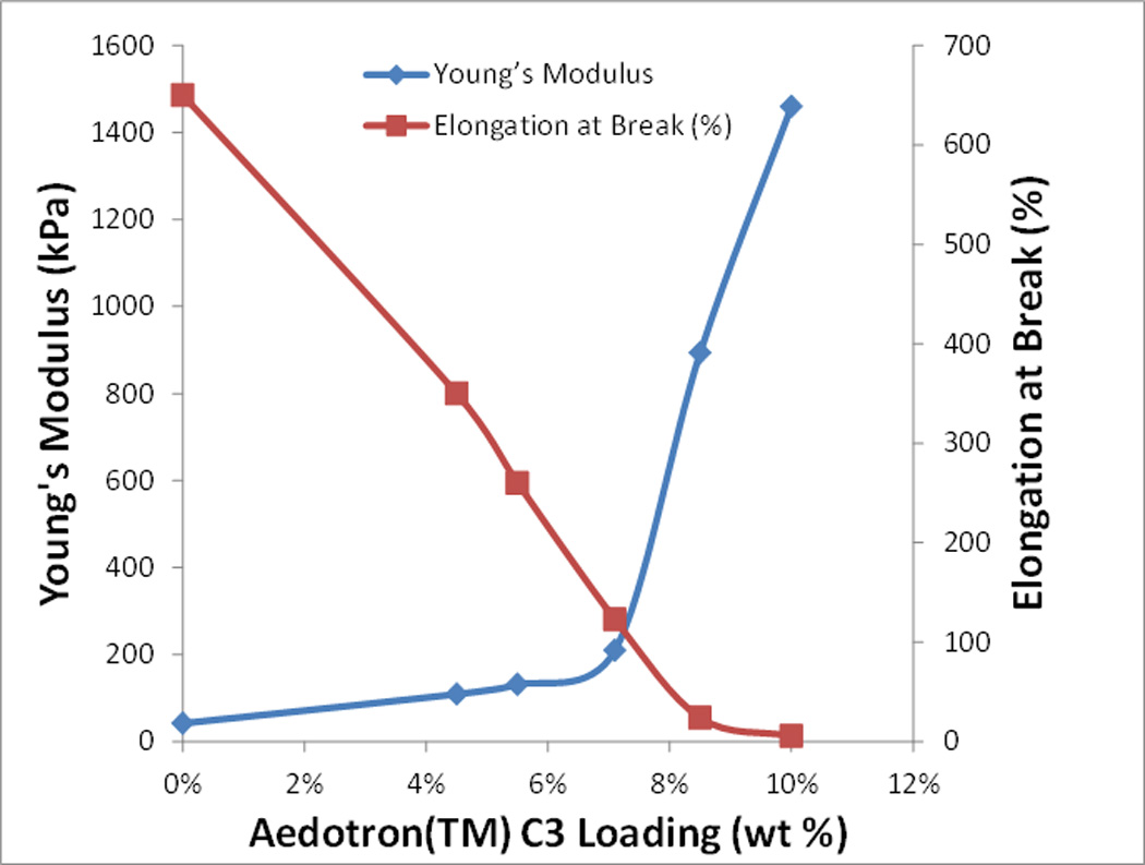
The young’s modulus (blue trace) and elongation at break (red trace) of conducting elastomers as a function of aedotron™ c3 loading.
We next evaluated the effect of adding an insulating coating to the mechanical properties of the wires while controlling the coating thickness to reduce the overall size of the electrode for in vivo use. Parylene C-coated wires had significantly different mechanical properties than the corresponding uncoated wires despite the thin coating (3 µm) (compare the first and third rows of data, Table 3); the Young’s modulus of the coated wire was an order of magnitude higher than that of the uncoated wire, and the elongation at break increased from 123% to 576%. In contrast, insulating shrouds made of FS did not significantly change the mechanical properties of the electrode when compared to the uncoated wire although a slight decrease in the Young’s modulus was observed (from 800 kPa to 638 kPa; Table 3, rows 3 and 4). Moreover, the addition of a lining along the length of the electrode did not significantly change the mechanical properties of the finished electrode (last two rows in Table 3). These changes factored into the decision to utilize the FS coating for in vivo studies since the FS-coated wires had a significantly lower modulus than the Parylene C-coated wires.
Table 3.
Comparison of mechanical properties of uncoated and coated soft wires.
| Wire diameter ± SD (µm) |
Young’s Modulus ± SD (kPa) |
Ultimate Tensile Strength ± SD (MPa) |
Elongation at Break ± SD (%) |
|
|---|---|---|---|---|
| Uncoated, 7% filled | 168 ± 9 | 190 ± 17 | 2.3 ± 0.3 | 123 ± 17 |
| Parylene C coated, 7% filled | 174 ± 10 | 1975±165 | 9.8 ± 0.8 | 576 ± 115 |
| Uncoated, 8.5% filled | 114 | 800 ± 82 | 2.6 ± 0.6 | 16 ± 5.0 |
| FS coated, 8.5% filled | 124 ± 9 | 638 ± 109 | 5.5 ± 0.5 | 38 ± 10 |
| FS coated, 8.5% filled, gold lined | 125 ± 3 | 974 ± 258 | 5.2 ± 0.9 | 27 ± 10 |
To evaluate the ability of our soft wires to handle repeated deformations, the resistance of a 25G, 8.5% filled, FS-coated electrode was plotted against the number of bending-unbending events (Figure 5). A "bend" was defined as one 180° bend around a radius of curvature of 5 mm, which corresponds to an approximately 3.6% elongation of the outer surface of the electrode compared to the inner surface. While the data is noisy due to the poor contact resistance between the wire tip and the copper, overall the electrode resistance changed less than 5% after 200 bending-unbending events. This is a promising result for the intended application. The initial drop in resistance observed within the first 50 cycles is likely due to a partial stretch-induced alignment of the conducting domains within the wire composite material. Importantly, this does not indicate a degradation in electrode performance as the conductivity of the electrode actually increases with the number of bending events.
Figure 5.
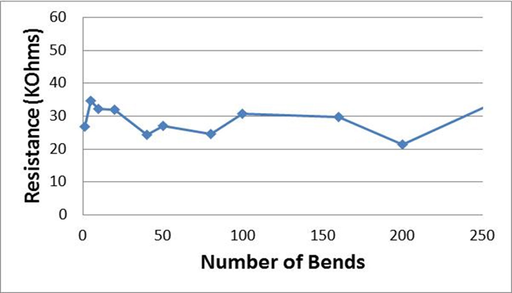
Electrical properties following repeated elastic deformation. the resistance of a 25g, 8.5% filled, fs-coated electrode as a function of the number of 180° bending-unbending events around a mandrel 0.5 cm in diameter.
Electrochemical characterization
Cyclic voltammetry (CV) was then used to characterize the electrochemical properties of the fabricated electrodes. From these studies, the electrochemical potential window from −0.5 to +1.0 V (vs. Ag/AgCl) was identified as a stable window in which to utilize the soft wires (Figure 6). Scanning outside of this range (either more negative or more positive) resulted in minor Faradaic current signals.
Figure 6.
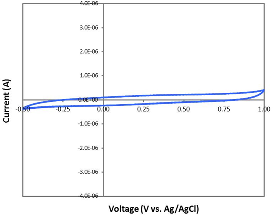
Cyclic voltammetry (cv) scans obtained at 50 mv/s for a 29g 8.5% filled, gold-lined, tip-trimmed, fs coated soft wire over its stable potential window. the electrodes show clean capacitive charging with no signs of redox processes in the window of potential from −0.5v to 1.0 v vs. ag/agcl.
The impedance magnitude at 1 kHz was obtained from Electrochemical Impedance Spectroscopy (EIS) run in PBS and compared with other known materials (Table 4, second column). Testing was performed on soft wires using three standard extrusion sizes. Some of the tested soft wires contained no metallic conductors (A, B and C in Table 4), while some electrodes were lined with a few angstrom-thick coating of gold (D, E and F in Table 4). The gold lining ended 2 mm from the tip of the electrode and therefore was not in direct contact with the solution (Supplemental Figure 1). For most of the tested soft electrodes the active areas was equal to the cross-section area of the wire. However, for the last specimen (G in Table 4), the surface active area of the electrode was reduced from roughly 22,000 m2 to 3,900 m2 by bias-cutting the tip (see Supplemental Figure 1). The impedances and charge densities were compared to those of stiff metallic electrodes including probes made of iridium metal, iridium oxide and PEDOT-PSS-coated iridium metal (H, I and L in Table 4) [78]. As expected, smaller electrodes tended to have the highest impedance values (for a given group of electrode types). The impedance of our soft electrodes was lower than that of iridium metal and iridium oxide electrodes and, more importantly, the values are in the middle-to-lower portion of the acceptable range of impedance values for central nervous system electrodes [79], and in some cases, even lower. This suggests that further reduction of the active area of the soft electrodes is possible even with the expected increase in impedance [34]. In addition, the ability to adjust the formulation filler loading to a higher or lower fill ratio provides a mean to tune the impedance value. Even without these alterations, the novel soft electrodes have impedance similar to PEDOT-PSS-coated metallic neural probes and lower than uncoated iridium probes. PEDOT-coated metallic electrodes tend to fail by delamination of the PEDOT coating from the metal [63]. In our electrodes, the PEDOT is not a coating but constitutes a fraction of the entire core of the wire. Therefore, our electrode design eliminates the delamination failure while taking advantage of the lower modulus material, a significant improvement for long-term applications.
Table 4.
Electrochemical properties of fabricated soft electrodes. All measurements taken in standard PBS solution with a Pt coil counter and Ag/AgCl reference electrodes, cycling between −0.5 V and +1.0 V. Comparative data (last 3 rows) taken from [78].
| Sample | Impendence @ 1kHz (kOhms) |
Charge Density Qcap @ 50 mV/s, cathodic (mC/cm2) |
|
|---|---|---|---|
| A | 22 G (diam. 285 µm), 7.1% filled wire, PDMS coated | 19.2 | 49.0 |
| B | 26 G (diam. 179 µm), 7.1% filled wire, PDMS coated | 45.8 | 24.0 |
| C | 29 G (diam. 168 µm), 7.1% filled wire, PDMS coated | 90.8 | 26.8 |
| D | 22 G (diam. 285 µm), 7.1% filled wire, Au-lined, PDMS-coated | 4.65 | 70.2 |
| E | 26 G (diam. 179 µm), 7.1% filled wires, Au-lined, PDMS-coated | 31.2 | 65.0 |
| F | 29 G (diam. 160 µm), 7.1% filled wires, Au-lined, PDMS-coated (active area 22,000 um2) | 54.2 | 93.8 |
| G | 29 G (diam. 160 µm), 8.5% filled wires, Au-lined, FS-coated, tip trimmed (Active area 3900 um2) | 124 | 138.0 |
| H | 23 µm diam. PEDOT-PSS electrodeposited on iridium | 23.3 | 76.0 |
| I | 23 µm diam. iridium oxide | 114 | 28.8 |
| J | 23 µm diam. iridium metal | 404 | <5 |
The surface charging capacity of the soft electrodes in PBS was calculated from CV scans obtained at the scan rate of 50 mV/s over the electrochemical stability window by integration of the current trace. At this scan rate, these values represent the near steady-state electrode performance (Table 4, last column). Generally, a larger charge capacity is associated with improved electrode material performance. In almost all cases, 29G soft electrodes had higher charge densities than electrodes made of standard materials, albeit at a larger size. This demonstrates that conducting polymers, even when blended at only 8.5% in silicone, exhibit the unique behavior of extremely high surface charge density. In addition, gold sputtered electrodes are generally associated with lower impedance and less variation in electronic properties.
In Vitro Cell Culture
For clinical use, the fabrication of soft wires (conducting core + insulating coating) must demonstrate good biocompatibility. Therefore, soft wires (114–130 µm in diameter and 638 or 974 kPa in modulus) were tested using an in vitro cell culture system and compared to 120 m diameter stiff microwires (control) made out of tungsten (Young’s Modulus = 400 GPa). Neurons, astrocytes and microglia were plated separately onto the surfaces of the control wires, Parylene C-coated soft wires and FS-coated soft wires. Each wire was fixed at one end to the bottom of a glass coverslip inserted into the well of a 24-well plate to mimic micromotion-induced forces in this in vitro setting. Prior to initiating these cell culture experiments, tests to assess sterilization methods were performed with eventual clinical applications in mind. No neuronal toxicity was observed with ethylene oxide (EtO) sterilization (data not shown), and the remaining studies were carried out with EtO-sterilized wires.
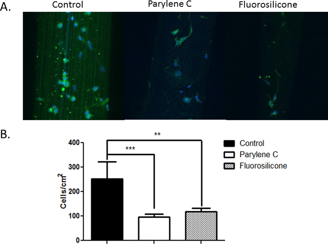
For neural recording and stimulation applications, neurons must remain in close proximity to implanted neural electrodes. Therefore, the degree of neuronal attachment achieved with the soft electrodes was tested. Compared to the stiff wire controls, increased neuronal attachment was observed for both the Parylene C and the FS coatings with statistically significant increases for the FS-coated soft wires compared to controls (Figure 7). These results indicate that the interaction between neurons and the fluorosilicone surfaces is favorable and sustainable in the presence of micromovement. However, variations in surface roughness (physical texture) rather than simply chemical composition may have an impact as well [34, 80]. Importantly, increases in neuronal attachment and density at the neural electrode-tissue interface could impact long-term functionality resulting in improved chronic recording with FS-coated soft wires compared to stiff wires.
Figure 7.
Primary neurons were cultured with control and soft wires. representative images reconstructed from z-stacked images depicting neurons (green, stained for β3-tubulin) attached to the surface of the wires (a). quantification of neuronal cell adhesion on the surfaces of the wires (b) showing significantly greater neuronal attachment with fs-coated soft wires compared to control stiff wires and parylene c-coated soft wires. ***p < 0.001.
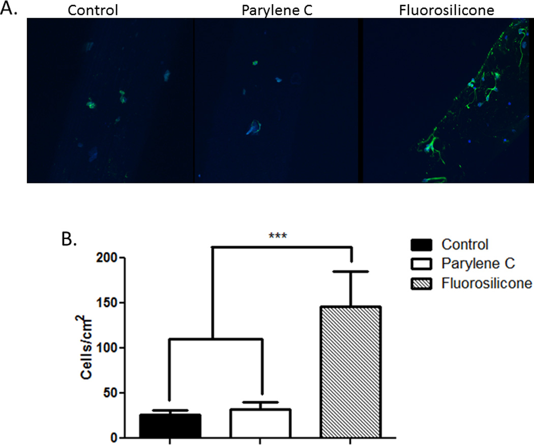
Attachment of two other cells of the CNS (microglia and astrocytes) highly involved in the brain tissue responses to implants was also evaluated. These cells play important roles in determining the fate of implanted devices. More specifically, macrophages and activated microglia migrate to the neural electrode-tissue interface almost immediately after electrode insertion [36], remaining there for as long as the implant remains in contact with brain tissue [14]. As a result of this proximity to the implanted device, these cells may be most directly impacted by micromotion-induced forces. For both soft wire types, significant decreases in microglia attachment were observed when compared to the stiff wires (Figure 8). This decrease in microglial attachment in combination with the decrease in mechanical strain could result in an improved electrode-tissue interface. Indeed, improved tissue responses have been observed with compliant [52–59] and mechanically-adaptive materials [60, 61], and ongoing studies will be used to evaluate our novel soft wires in vivo.
Figure 8.
Microglia were cultured with control and soft wires. representative images reconstructed from z-stacked images depicting hapi cells (green, stained for ed1) attached to the surface of the wires (a). quantification of microglia adhesion on the surface of the wires (b) showing significant decreases with both soft wires (fs-coated and parylene-c coated) as compared to control stiff wires. ***p < 0.001; **p < 0.01.
Protein Immobilization on Insulating Surfaces
Proteins were also immobilized on the insulating coating to improve the cellular response to these materials. Both laminin, a basement membrane protein important in neural development and axonal outgrowth, and L1, a neural adhesion molecule, were immobilized onto Parylene C and FS surfaces and the cellular attachment assessed. Both insulating surfaces were modifiable as demonstrated by increased neuronal attachment and neurite outgrowth in the presence of either laminin or L1 as compared to the unmodified control surfaces (data not shown). This is an important feature of these materials as it could further promote the biocompatibility and successful integration of implanted neural probes. To better understand the impact of combining the soft materials and the protein coating, laminin and L1 were immobilized on the surface of the soft wires and cellular attachment quantified. Significant increases in neuronal attachment were observed with the L1 coating on FS-coated soft wires while laminin-coated surfaces significantly increased the attachment of astrocytes consistent with previous results from our laboratory [67] (Figure 9). Interestingly, no significant differences in the attachment of microglia were observed although phenotypic changes in these cells could be affected. L1 is a protein known for its roles in cell-cell recognition [81, 82], neurite outgrowth [83, 84], neuronal connectivity [82] and synaptic plasticity [81, 85]. In particular, our laboratory has demonstrated reduced neuronal cell death, increased axonal density and decreased activation of microglia and astrocytes with L1-coated electrodes in vivo [66, 67]. Notably, these biomolecule coatings remained stable even after 5 days of soaking with no significant decrease in neuronal attachment observed (data not shown).
Figure 9.

Cellular attachment after surface modification of soft wires. protein coatings were applied to the surface of soft wires and primary neurons (a), astrocytes (b) or microglia (c) were plated onto the soft wires. quantification of cell adhesion on the surfaces of the wires indicates significantly different attachment with laminin and l1 coatings. ***p < 0.001; *p < 0.05.
In Vivo Functionality
Finally, to assess the electrophysiology functionality of the soft electrodes, a soft wire (125 m diameter, 974 kPa modulus, specimen G in Table 4) with a tapered tip was implanted in the rodent visual cortex (Figure 10). Drifting bar stimulation was utilized to drive neural activity in the visual cortex. The sorted single-unit was not activated during every stimulation sequence suggesting the activity was not an artifact of the stimulation set-up. An autocorrelogram was used to examine the inter-spike interval (ISI) as neurons are unable to fire a second action potential while in the refractory period (~1 ms). The ISI distribution pattern is consistent with an extracellular action potential recorded from a neuron, further support that the unit activity is of neural origin.
Figure 10.
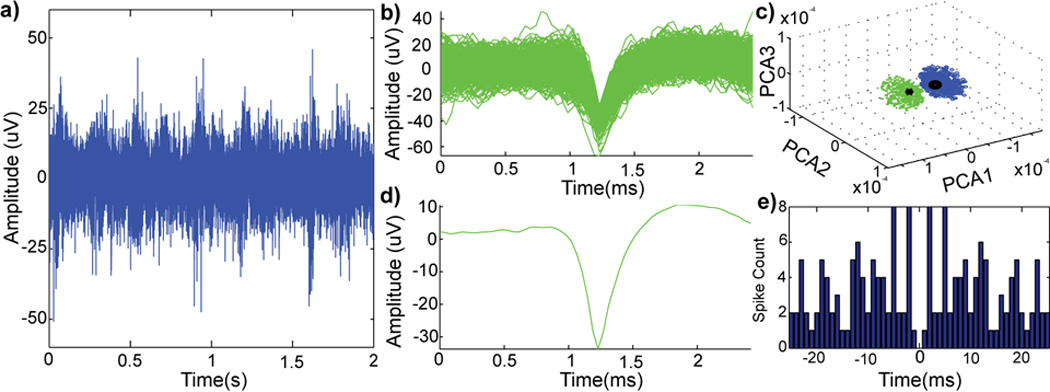
In vivo performance of implanted soft electrodes with visual cortex stimulation. a two-second example of raw spike stream (300–5,000 hz; noise floor = 15 µv) (a) from a neural recording with visual stimulation. pile-plot of isolated single-unit waveforms (b) from (a). principle component cluster (c) of single-units (green) and noise cluster (blue). mean waveform (d) of the sorted single-unit (snr 2.96) and autocorrelogram (e) of the sorted single-unit.
Detected single-units had low signal-to-noise ratio (SNR) and amplitude. This is likely due to the size of the recording site (~3,900 µm2), which is over three times larger than electrode sites of commercially available neural electrodes (i.e., NeuroNexus Technologies probes have electrode site sizes ranging from 177–1,250 µm2). Furthermore, the total volume of implanted probe in the tissue is relatively large; this can lead to an increase in acute tissue strain caused by tissue displacement and compression due to probe implantation [29]. Nevertheless, this result is encouraging as this is the first time a soft wire electrode made of novel elastomeric polymer blends showed ability to record single unit neural signals. Such positive result warrants further optimization studies and testing in chronic implantation. It is possible that recording performance may improve in the chronic phase as the tissue equilibrates after probe volume-induced strain and benefits from the reduced elastic modulus can be realized. In addition, reducing the dimensions of the soft wires may further enhance chronic recording capabilities. Future work will also evaluate this soft electrode technology in neural stimulation and peripheral applications [86].
Conclusions
In this study, novel soft electrodes including a conducting polymer blend core and an insulating biomimetic coating material were developed to improve the biocompatibility of neural probes and decrease the chronic inflammation and degeneration observed when a mechanical mismatch exists between neural probes and neural tissues. The mechanical and electrochemical properties of these novel elastomeric electrodes were characterized, and the surface morphology revealed a homogeneous distribution of conducting and non-conducting domains within the polymer core. By altering the ratio of elastomer to conducting polymer within the core, a formulation including MED6607 with 8.5% Aedotron™ C3 was identified as the optimal balance of low impendence, high charge injection. low Young’s modulus, and sufficient tensile strength. These soft electrodes have Young’s modulus more than three orders of magnitude lower than polyimide and five orders of magnitude lower than tungsten. They demonstrated capacitive charging similar to tungsten electrodes without undergoing reduction and oxidation processes. In addition, resistance remained constant even after hundreds of bending-unbending events indicating the durability of the electrodes. Parylene C and FS coatings were added to provide a layer of insulation around the conductive core. Both of these coatings were able to support the growth of neurons, astrocytes and microglia; coated surfaces were also amenable to protein modifications designed to improve neuronal attachment and neurite outgrowth. In fact, soft electrodes resulted in more than a two-fold reduction in microglia attachment in a cell culture environment that included electrode micromotion indicating that a reduced inflammatory host tissue response could be achieved in vivo. Finally, FS-coated soft electrodes were able to record neural action potentials in the visual cortex in response to stimulation. Taken together, this work suggests that low modulus, biocompatible, modifiable materials have enormous clinical potential with the capacity to improve electrode performance for neural interfacing applications.
Supplementary Material
Acknowledgments
This work was sponsored by the Defense Advanced Research Projects Agency (DARPA) Contracts No. W31P4Q-08-C-0460 and W31P4Q-11-C-0134 and NIH R01 (5R01NS062019). The authors also wish to thank the Center for Biologic Imaging at the University of Pittsburgh for microscope assistance.
Footnotes
Declaration of Competing Financial Interests
Dr. Silvia Luebben is affiliated with TDA Research, Inc., Golden, CO who manufactures and sells Aedotron™ C3.
References
- 1.Buzsaki G. Large-scale recording of neuronal ensembles. Nat Neurosci. 2004;7(5):446–451. doi: 10.1038/nn1233. [DOI] [PubMed] [Google Scholar]
- 2.Schwartz AB. Cortical neural prosthetics. Annu Rev Neurosci. 2004;27:487–507. doi: 10.1146/annurev.neuro.27.070203.144233. [DOI] [PubMed] [Google Scholar]
- 3.Collinger JL, et al. High-performance neuroprosthetic control by an individual with tetraplegia. Lancet. 2013;381(9866):557–564. doi: 10.1016/S0140-6736(12)61816-9. [DOI] [PMC free article] [PubMed] [Google Scholar]
- 4.Nicolelis MA, et al. Chronic, multisite, multielectrode recordings in macaque monkeys. Proc Natl Acad Sci U S A. 2003;100(19):11041–11046. doi: 10.1073/pnas.1934665100. [DOI] [PMC free article] [PubMed] [Google Scholar]
- 5.Chestek CA, et al. Long-term stability of neural prosthetic control signals from silicon cortical arrays in rhesus macaque motor cortex. J Neural Eng. 2011;8(4):045005. doi: 10.1088/1741-2560/8/4/045005. [DOI] [PMC free article] [PubMed] [Google Scholar]
- 6.Wise KD, et al. Wireless implantable microsystems: High-density electronic interfaces to the nervous system. Proceedings of the IEEE. 2004 [Google Scholar]
- 7.Vetter RJ, et al. Chronic neural recording using silicon-substrate microelectrode arrays implanted in cerebral cortex. IEEE Trans Biomed Eng. 2004;51(6):896–904. doi: 10.1109/TBME.2004.826680. [DOI] [PubMed] [Google Scholar]
- 8.Liu X, et al. Stability of the interface between neural tissue and chronically implanted intracortical microelectrodes. IEEE Transactions on Rehabilitation Engineering: A Publication of the IEEE Engineering in Medicine and Biology Society. 1999;7(3):315–326. doi: 10.1109/86.788468. [DOI] [PubMed] [Google Scholar]
- 9.Williams JC, Rennaker RL, Kipke DR. Long-term neural recording characteristics of wire microelectrode arrays implanted in cerebral cortex. Brain Res Brain Res Protoc. 1999;4(3):303–313. doi: 10.1016/s1385-299x(99)00034-3. [DOI] [PubMed] [Google Scholar]
- 10.Rousche PJ, Normann RA. Chronic recording capability of the Utah Intracortical Electrode Array in cat sensory cortex. J Neurosci Methods. 1998;82(1):1–15. doi: 10.1016/s0165-0270(98)00031-4. [DOI] [PubMed] [Google Scholar]
- 11.Stensaas SS, Stensaas LJ. The reaction of the cerebral cortex to chronically implanted plastic needles. Acta Neuropathol. 1976;35(3):187–203. [PubMed] [Google Scholar]
- 12.Ward MP, et al. Toward a comparison of microelectrodes for acute and chronic recordings. Brain Res. 2009;1282:183–200. doi: 10.1016/j.brainres.2009.05.052. [DOI] [PubMed] [Google Scholar]
- 13.Schwartz AB, et al. Brain-controlled interfaces: movement restoration with neural prosthetics. Neuron. 2006;52(1):205–220. doi: 10.1016/j.neuron.2006.09.019. [DOI] [PubMed] [Google Scholar]
- 14.Szarowski DH, et al. Brain responses to micro-machined silicon devices. Brain Res. 2003;983(1–2):23–35. doi: 10.1016/s0006-8993(03)03023-3. [DOI] [PubMed] [Google Scholar]
- 15.Polikov VS, Tresco PA, Reichert WM. Response of brain tissue to chronically implanted neural electrodes. J Neurosci Methods. 2005;148(1):1–18. doi: 10.1016/j.jneumeth.2005.08.015. [DOI] [PubMed] [Google Scholar]
- 16.Kozai TD, et al. Effects of caspase-1 knockout on chronic neural recording quality and longevity: insight into cellular and molecular mechanisms of the reactive tissue response. Biomaterials. 2014;35(36):9620–9634. doi: 10.1016/j.biomaterials.2014.08.006. [DOI] [PMC free article] [PubMed] [Google Scholar]
- 17.Kozai TD, et al. In vivo two-photon microscopy reveals immediate microglial reaction to implantation of microelectrode through extension of processes. J Neural Eng. 2012;9(6):066001. doi: 10.1088/1741-2560/9/6/066001. [DOI] [PMC free article] [PubMed] [Google Scholar]
- 18.Leach JB, Achyuta AK, Murthy SK. Bridging the Divide between Neuroprosthetic Design, Tissue Engineering and Neurobiology. Front Neuroeng. 2010;2:18. doi: 10.3389/neuro.16.018.2009. [DOI] [PMC free article] [PubMed] [Google Scholar]
- 19.McKeon RJ, et al. Reduction of neurite outgrowth in a model of glial scarring following CNS injury is correlated with the expression of inhibitory molecules on reactive astrocytes. J Neurosci. 1991;11(11):3398–3411. doi: 10.1523/JNEUROSCI.11-11-03398.1991. [DOI] [PMC free article] [PubMed] [Google Scholar]
- 20.Turner JN, et al. Cerebral astrocyte response to micromachined silicon implants. Experimental Neurology. 1999;156(1):33–49. doi: 10.1006/exnr.1998.6983. [DOI] [PubMed] [Google Scholar]
- 21.Silver J, Miller JH. Regeneration beyond the glial scar. Nat Rev Neurosci. 2004;5(2):146–156. doi: 10.1038/nrn1326. [DOI] [PubMed] [Google Scholar]
- 22.Pekny M, Nilsson M. Astrocyte activation and reactive gliosis. Glia. 2005;50(4):427–434. doi: 10.1002/glia.20207. [DOI] [PubMed] [Google Scholar]
- 23.Roitbak T, Sykova E. Diffusion barriers evoked in the rat cortex by reactive astrogliosis. Glia. 1999;28(1):40–48. doi: 10.1002/(sici)1098-1136(199910)28:1<40::aid-glia5>3.0.co;2-6. [DOI] [PubMed] [Google Scholar]
- 24.Reier P, Stensaas L, Guth L. Spinal Cord Reconstruction. New York: Raven Press; 1983. The astrocytic scar as an impediment to regeneration in the central nervous system. [Google Scholar]
- 25.Edell DJ, et al. Factors influencing the biocompatibility of insertable silicon microshafts in cerebral cortex. IEEE Trans Biomed Eng. 1992;39(6):635–643. doi: 10.1109/10.141202. [DOI] [PubMed] [Google Scholar]
- 26.He W, Bellamkonda RV. In: A Molecular Perspective on Understanding and Modulating the Performance of Chronic Central Nervous System (CNS) Recording Electrodes, in Indwelling Neural Implants: Strategies for Contending with the In Vivo Environment. Reichert WM, editor. Boca Raton (FL): 2008. [PubMed] [Google Scholar]
- 27.Kozai TDY, et al. Chronic tissue response to carboxymethyl cellulose based dissolvable insertion needle for ultra-small neural probes. Biomaterials. 2014;35:9255–9268. doi: 10.1016/j.biomaterials.2014.07.039. [DOI] [PubMed] [Google Scholar]
- 28.Biran R, Martin DC, Tresco PA. Neuronal cell loss accompanies the brain tissue response to chronically implanted silicon microelectrode arrays. Exp Neurol. 2005;195(1):115–126. doi: 10.1016/j.expneurol.2005.04.020. [DOI] [PubMed] [Google Scholar]
- 29.Kozai TDY, et al. Effects of caspase-1 knockout on chronic neural recording quality and longevity: Insight into cellular and molecular mechanisms of the reactive tissue response. Biomaterials. 2014 doi: 10.1016/j.biomaterials.2014.08.006. [DOI] [PMC free article] [PubMed] [Google Scholar]
- 30.McConnell GC, et al. Implanted neural electrodes cause chronic, local inflammation that is correlated with local neurodegeneration. J Neural Eng. 2009;6(5):056003. doi: 10.1088/1741-2560/6/5/056003. [DOI] [PubMed] [Google Scholar]
- 31.Karumbaiah L, et al. The upregulation of specific interleukin (IL) receptor antagonists and paradoxical enhancement of neuronal apoptosis due to electrode induced strain and brain micromotion. Biomaterials. 2012;33(26):5983–5996. doi: 10.1016/j.biomaterials.2012.05.021. [DOI] [PubMed] [Google Scholar]
- 32.Saxena T, et al. The impact of chronic blood-brain barrier breach on intracortical electrode function. Biomaterials. 2013;34(20):4703–4713. doi: 10.1016/j.biomaterials.2013.03.007. [DOI] [PubMed] [Google Scholar]
- 33.Kozai TDY, et al. Reduction of neurovascular damage resulting from microelectrode insertion into the cerebral cortex using in vivo two-photon mapping. J Neural Eng. 2010;7(4):046011. doi: 10.1088/1741-2560/7/4/046011. [DOI] [PMC free article] [PubMed] [Google Scholar]
- 34.Kozai T, et al. In: Nanostructured coatings for improved charge delivery to neurons, in Nanotechnology and neuroscience: nano-electronic, photonic and mechanical neuronal interfacing. Vittorio MD, Martiradonna L, Assad J, editors. New York: Springer New York, NY; 2014. pp. 71–134. [Google Scholar]
- 35.Kozai TDY, et al. Ultrasmall implantable composite microelectrodes with bioactive surfaces for chronic neural interfaces. Nature Materials. 2012;11(12):1065–1073. doi: 10.1038/nmat3468. [DOI] [PMC free article] [PubMed] [Google Scholar]
- 36.Kozai TDY, et al. In vivo two photon microscopy reveals immediate microglial reaction to implantation of microelectrode through extension of processes. J Neural Eng. 2012;9:066001. doi: 10.1088/1741-2560/9/6/066001. [DOI] [PMC free article] [PubMed] [Google Scholar]
- 37.Prasad A, et al. Abiotic-biotic characterization of Pt/Ir microelectrode arrays in chronic implants. Front Neuroeng. 2014;7:2. doi: 10.3389/fneng.2014.00002. [DOI] [PMC free article] [PubMed] [Google Scholar]
- 38.Seymour JP, Kipke DR. Neural probe design for reduced tissue encapsulation in CNS. Biomaterials. 2007;28(25):3594–3607. doi: 10.1016/j.biomaterials.2007.03.024. [DOI] [PubMed] [Google Scholar]
- 39.Biran R, Martin DC, Tresco PA. The brain tissue response to implanted silicon microelectrode arrays is increased when the device is tethered to the skull. J Biomed Mater Res A. 2007;82(1):169–178. doi: 10.1002/jbm.a.31138. [DOI] [PubMed] [Google Scholar]
- 40.Fallenstein GT, Hulce VD, Melvin JW. Dynamic mechanical properties of human brain tissue. J Biomech. 1969;2(3):217–226. doi: 10.1016/0021-9290(69)90079-7. [DOI] [PubMed] [Google Scholar]
- 41.Miller K, et al. Mechanical properties of brain tissue in-vivo: experiment and computer simulation. J Biomech. 2000;33(11):1369–1376. doi: 10.1016/s0021-9290(00)00120-2. [DOI] [PubMed] [Google Scholar]
- 42.Lu YB, et al. Viscoelastic properties of individual glial cells and neurons in the CNS. Proc Natl Acad Sci U S A. 2006;103(47):17759–17764. doi: 10.1073/pnas.0606150103. [DOI] [PMC free article] [PubMed] [Google Scholar]
- 43.Georges PC, et al. Matrices with compliance comparable to that of brain tissue select neuronal over glial growth in mixed cortical cultures. Biophys J. 2006;90(8):3012–3018. doi: 10.1529/biophysj.105.073114. [DOI] [PMC free article] [PubMed] [Google Scholar]
- 44.Moshayedi P, et al. The relationship between glial cell mechanosensitivity and foreign body reactions in the central nervous system. Biomaterials. 2014;35(13):3919–3925. doi: 10.1016/j.biomaterials.2014.01.038. [DOI] [PubMed] [Google Scholar]
- 45.Subbaroyan J, Martin DC, Kipke DR. A finite-element model of the mechanical effects of implantable microelectrodes in the cerebral cortex. J Neural Eng. 2005;2(4):103–113. doi: 10.1088/1741-2560/2/4/006. [DOI] [PubMed] [Google Scholar]
- 46.Neary JT, et al. Activation of extracellular signal-regulated kinase by stretch-induced injury in astrocytes involves extracellular ATP and P2 purinergic receptors. J Neurosci. 2003;23(6):2348–2356. doi: 10.1523/JNEUROSCI.23-06-02348.2003. [DOI] [PMC free article] [PubMed] [Google Scholar]
- 47.LaPlaca MC, et al. High rate shear strain of three-dimensional neural cell cultures: a new in vitro traumatic brain injury model. J Biomech. 2005;38(5):1093–1105. doi: 10.1016/j.jbiomech.2004.05.032. [DOI] [PubMed] [Google Scholar]
- 48.Tew GN, et al. New properties from PLA-PEO-PLA hydrogels. Soft Matter. 2005;1(4):253–258. doi: 10.1039/b509800a. [DOI] [PubMed] [Google Scholar]
- 49.Williams JC, et al. Complex impedance spectroscopy for monitoring tissue responses to inserted neural implants. J Neural Eng. 2007;4(4):410–423. doi: 10.1088/1741-2560/4/4/007. [DOI] [PubMed] [Google Scholar]
- 50.Kozai TDY, et al. Mechanical failure modes of chronically implanted planar silicon-based neural probes for laminar recording. Biomaterials. doi: 10.1016/j.biomaterials.2014.10.040. (in press). [DOI] [PMC free article] [PubMed] [Google Scholar]
- 51.Lee H, et al. Biomechanical analysis of silicon microelectrode-induced strain in the brain. J Neural Eng. 2005;2(4):81–89. doi: 10.1088/1741-2560/2/4/003. [DOI] [PubMed] [Google Scholar]
- 52.Wester BA, Lee RH, LaPlaca MC. Development and characterization of in vivo flexible electrodes compatible with large tissue displacements. J Neural Eng. 2009;6(2):024002. doi: 10.1088/1741-2560/6/2/024002. [DOI] [PMC free article] [PubMed] [Google Scholar]
- 53.Takeuchi S, et al. Parylene flexible neural probes integrated with microfluidic channels. Lab Chip. 2005;5(5):519–523. doi: 10.1039/b417497f. [DOI] [PubMed] [Google Scholar]
- 54.Rousche PJ, et al. Flexible polyimide-based intracortical electrode arrays with bioactive capability. IEEE Trans Biomed Eng. 2001;48(3):361–371. doi: 10.1109/10.914800. [DOI] [PubMed] [Google Scholar]
- 55.Lu Y, et al. Poly(vinyl alcohol)/poly(acrylic acid) hydrogel coatings for improving electrode-neural tissue interface. Biomaterials. 2009;30(25):4143–4151. doi: 10.1016/j.biomaterials.2009.04.030. [DOI] [PubMed] [Google Scholar]
- 56.Subbaroyan J, Kipke DR. The role of flexible polymer interconnects in chronic tissue response induced by intracortical microelectrodes--a modeling and an in vivo study. Conf Proc IEEE Eng Med Biol Soc. 2006;1:3588–3591. doi: 10.1109/IEMBS.2006.260517. [DOI] [PubMed] [Google Scholar]
- 57.Mercanzini A, et al. In vivo electrical impedance spectroscopy of tissue reaction to microelectrode arrays. IEEE Trans Biomed Eng. 2009;56(7):1909–1918. doi: 10.1109/TBME.2009.2018457. [DOI] [PubMed] [Google Scholar]
- 58.Kozai TDY, Kipke DR. Insertion shuttle with carboxyl terminated self-assembled monolayer coatings for implanting flexible polymer neural probes in the brain. J Neurosci Methods. 2009;184(2):199–205. doi: 10.1016/j.jneumeth.2009.08.002. [DOI] [PMC free article] [PubMed] [Google Scholar]
- 59.Gilgunn PJ, et al. An ultra-compliant, scalable neural probes with molded biodissolvable delivery vehicle. Micro Electro Mechanical Systems (MEMS), 2012 IEEE 25th International Conference on. 2012;2012:56–59. [Google Scholar]
- 60.Harris JP, et al. In vivo deployment of mechanically adaptive nanocomposites for intracortical microelectrodes. J Neural Eng. 2011;8(4):046010. doi: 10.1088/1741-2560/8/4/046010. [DOI] [PMC free article] [PubMed] [Google Scholar]
- 61.Ware T, et al. Thiol-click chemistries for responsive neural interfaces. Macromol Biosci. 2013;13(12):1640–1647. doi: 10.1002/mabi.201300272. [DOI] [PMC free article] [PubMed] [Google Scholar]
- 62.Richardson-Burns SM, Hendricks JL, Martin DC. Electrochemical polymerization of conducting polymers in living neural tissue. J Neural Eng. 2007;4(2):L6–L13. doi: 10.1088/1741-2560/4/2/L02. [DOI] [PubMed] [Google Scholar]
- 63.Cui XT, Zhou DD. Poly (3,4-ethylenedioxythiophene) for chronic neural stimulation. IEEE Trans Neural Syst Rehabil Eng. 2007;15(4):502–508. doi: 10.1109/TNSRE.2007.909811. [DOI] [PubMed] [Google Scholar]
- 64.Silvia D, Luebben SAS. United States of America: TDA Research, Inc.; 2010. Methods of production, purification, and processing of poly(heteroaromatic) block copolymers with improved solubility or dispersability. [Google Scholar]
- 65.Musallam S, et al. A floating metal microelectrode array for chronic implantation. J Neurosci Methods. 2007;160(1):122–127. doi: 10.1016/j.jneumeth.2006.09.005. [DOI] [PubMed] [Google Scholar]
- 66.Kolarcik CL, et al. In vivo effects of L1 coating on inflammation and neuronal health at the electrode-tissue interface in rat spinal cord and dorsal root ganglion. Acta Biomater. 2012;8(10):3561–3575. doi: 10.1016/j.actbio.2012.06.034. [DOI] [PMC free article] [PubMed] [Google Scholar]
- 67.Azemi E, Lagenaur CF, Cui XT. The surface immobilization of the neural adhesion molecule L1 on neural probes and its effect on neuronal density and gliosis at the probe/tissue interface. Biomaterials. 2011;32(3):681–692. doi: 10.1016/j.biomaterials.2010.09.033. [DOI] [PMC free article] [PubMed] [Google Scholar]
- 68.Azemi E, et al. Surface immobilization of neural adhesion molecule L1 for improving the biocompatibility of chronic neural probes: In vitro characterization. Acta Biomater. 2008;4(5):1208–1217. doi: 10.1016/j.actbio.2008.02.028. [DOI] [PubMed] [Google Scholar]
- 69.Cheepsunthorn P, et al. Characterization of a novel brain-derived microglial cell line isolated from neonatal rat brain. Glia. 2001;35(1):53–62. doi: 10.1002/glia.1070. [DOI] [PubMed] [Google Scholar]
- 70.Luo X, et al. Carbon nanotube nanoreservior for controlled release of anti-inflammatory dexamethasone. Biomaterials. 2011;32(26):6316–6323. doi: 10.1016/j.biomaterials.2011.05.020. [DOI] [PMC free article] [PubMed] [Google Scholar]
- 71.Kozai TD, Kipke DR. Insertion shuttle with carboxyl terminated self-assembled monolayer coatings for implanting flexible polymer neural probes in the brain. J Neurosci Methods. 2009;184(2):199–205. doi: 10.1016/j.jneumeth.2009.08.002. [DOI] [PMC free article] [PubMed] [Google Scholar]
- 72.Kozai TD, et al. Ultrasmall implantable composite microelectrodes with bioactive surfaces for chronic neural interfaces. Nat Mater. 2012;11(12):1065–1073. doi: 10.1038/nmat3468. [DOI] [PMC free article] [PubMed] [Google Scholar]
- 73.Brainard DH. The Psychophysics Toolbox. Spat Vis. 1997;10(4):433–436. [PubMed] [Google Scholar]
- 74.Pelli DG. The VideoToolbox software for visual psychophysics: transforming numbers into movies. Spat Vis. 1997;10(4):437–442. [PubMed] [Google Scholar]
- 75.Kleiner M, B D, Pelli D. What's new in Psychtoolbox-3? Perception. 2007;36 (ECVP Abstract Supplement). [Google Scholar]
- 76.Ludwig KA, et al. Chronic neural recordings using silicon microelectrode arrays electrochemically deposited with a poly(3,4-ethylenedioxythiophene) (PEDOT) film. J Neural Eng. 2006;3(1):59–70. doi: 10.1088/1741-2560/3/1/007. [DOI] [PubMed] [Google Scholar]
- 77.Luebben S, Elliott B, Wilson C. Poly(heteroaromatic) Block Copolymers with Electrical Conductivity. United States of America: 2007. [Google Scholar]
- 78.Wilks SJ, et al. Poly(3,4-ethylenedioxythiophene) as a Micro-Neural Interface Material for Electrostimulation. Front Neuroeng. 2009;2:7. doi: 10.3389/neuro.16.007.2009. [DOI] [PMC free article] [PubMed] [Google Scholar]
- 79.Cogan SF. Neural stimulation and recording electrodes. Annu Rev Biomed Eng. 2008;10:275–309. doi: 10.1146/annurev.bioeng.10.061807.160518. [DOI] [PubMed] [Google Scholar]
- 80.Lewandowska-Szumiel M, et al. Experimental model for observation of micromotion in cell culture. J Biomed Mater Res B Appl Biomater. 2005;72(2):379–387. doi: 10.1002/jbm.b.30172. [DOI] [PubMed] [Google Scholar]
- 81.Maness PF, Schachner M. Neural recognition molecules of the immunoglobulin superfamily: signaling transducers of axon guidance and neuronal migration. Nat Neurosci. 2007;10(1):19–26. doi: 10.1038/nn1827. [DOI] [PubMed] [Google Scholar]
- 82.Figge C, et al. Neurite outgrowth triggered by the cell adhesion molecule L1 requires activation and inactivation of the cytoskeletal protein cofilin. Mol Cell Neurosci. 2011 doi: 10.1016/j.mcn.2011.10.002. [DOI] [PubMed] [Google Scholar]
- 83.Lemmon V, Farr KL, Lagenaur C. L1-mediated axon outgrowth occurs via a homophilic binding mechanism. Neuron. 1989;2(6):1597–1603. doi: 10.1016/0896-6273(89)90048-2. [DOI] [PubMed] [Google Scholar]
- 84.Lagenaur C, Lemmon V. An L1-like molecule, the 8D9 antigen, is a potent substrate for neurite extension. Proc Natl Acad Sci U S A. 1987;84(21):7753–7757. doi: 10.1073/pnas.84.21.7753. [DOI] [PMC free article] [PubMed] [Google Scholar]
- 85.Kenwrick S, Watkins A, De Angelis E. Neural cell recognition molecule L1: relating biological complexity to human disease mutations. Hum Mol Genet. 2000;9(6):879–886. doi: 10.1093/hmg/9.6.879. [DOI] [PubMed] [Google Scholar]
- 86.Kolarcik CL, et al. Evaluation of poly(3,4-ethylenedioxythiophene)/carbon nanotube neural electrode coatings for stimulation in the dorsal root ganglion. Journal of Neural Engineering. 2014 doi: 10.1088/1741-2560/12/1/016008. [DOI] [PMC free article] [PubMed] [Google Scholar]
Associated Data
This section collects any data citations, data availability statements, or supplementary materials included in this article.