

Abstract
As tendons are loaded, they reduce in volume and exude fluid to the surrounding medium. Experimental studies have shown that tendon stretching results in a Poisson’s ratio greater than 0.5, with a maximum value at small strains followed by a nonlinear decay. Here we present a computational model that attributes this macroscopic observation to the microscopic mechanism of the load transfer between fibrils under stretch. We develop a finite element model based on the mechanical role of the interfibrillar-linking elements, such as thin fibrils that are bridging between the aligned fibrils or macromolecules such as glycosaminoglycans (GAGs) in the interfibrillar sliding and verify it with a theoretical shear-lag model. We showed the existence of a previously unappreciated structure-function mechanism whereby the Poisson’s ratio in tendon is affected by the strain applied and interfibrillar-linker properties, and together these features predict tendon volume shrinkage under tensile loading. During loading, the interfibrillar-linkers pulled fibrils towards each other and squeezed the matrix, leading to the Poisson’s ratio larger than 0.5 and fluid expulsion. In addition, the rotation of the interfibrillar-linkers with respect to the fibrils at large strains caused a reduction in the volume shrinkage and eventual nonlinear decay in Poisson’s ratio at large strains. Our model also predicts a fluid flow that has a radial pattern toward the surrounding medium, with the larger fluid velocities in proportion to the interfibrillar sliding.
Keywords: Finite element modeling, Poroelasticity, Poisson’s ratio, Tendon, Extracellular matrix
Graphical abstract
1. Introduction
Tendons function as mechanical, load-bearing structures that allow motion by transmitting forces from muscle to bone. The composition and organizational structure of tendon are optimized to allow its mechanical response for a range of stresses and strains. Under tensile loading, tendon exhibits shrinkage of volume [1] and fluid exudation to the surrounding medium [2,3]. By defining the Poisson’s ratio as (νeff = 1−ΔV/(εV0))/2), where (ΔV/V0 < 0) is the negative relative volume change at a tensile strain (ε), the Poisson’s ratio for tendon is expected to be larger than 0.5. Indeed, reported Poisson’s ratio for tendon are 1.65±0.35 for human hip joint ligament [4], 2.98±2.59 for sheep flexor tendon [5], and 0.7±0.52 for rat tail tendon fascicles [6]. Yet, mechanical models replicating this experimental behavior have been limited. Understanding the micromechanical response of tendon is therefore important to fully describe its material behavior from the macro to microstructural levels.
Tendons are composed of a dense extracellular matrix consisting primarily of collagenous and noncollagenous components. Modeling tendon as a distribution of fibrils embedded in a poroelastic matrix where the matrix adopts a Poisson’s ratio within the range of the homogenous isotropic materials (i.e. 0–0.5), predicts that tendons swell during tensile loading by absorbing fluid from the surrounding medium. This behavior is in contrast to the above experimental results [1–3] and to overcome this contradiction in previous poroelastic studies, the measured macroscopic Poisson’s ratio for the whole tendon (2.5 for sheep flexor [7] and 1.7 for rat tail [8]) was input as the microscopic Poisson’s ratio for the extracellular matrix (ECM). These large Poisson’s ratios for the ECM lead to the shrinkage of the matrix under tensile loading, and as a result, such models are capable of explaining the fluid exudation, although a concrete justification to equate the tendon and ECM Poisson’s ratios has not been presented. In addition these models are unable to predict the nonlinear variation of the Poisson’s ratio with strain; experiments have shown that tendons exhibit a large Poisson’s ratio (~6) at low strains that decays at high strains [9].
The biphasic behavior of tendon components implies that both collagen fibrils and the non-collagenous matrix play a role in stress transfer during uniaxial loading [10–17]. For example, proteoglycans (PGs) interact with and bind to type I collagen fibrils [18,19] at discrete sites with their protein cores, and their associated glycosaminoglycans (GAGs) extend into the interfibrillar matrix [19–22]. Evidence for binding of the GAG chains to certain domains on like molecules or to each other [23–26] suggests that GAGs may act as interfibrillar-links that contribute to fibril-fibril communication. Although recent models [27] have suggested that the contributions of PG-associated GAGs are greatest in the context of short, discrete fibrils likely during tendon development and healing, experimental studies in mature uninjured tendons have shown that, enzymatic digestion of GAGs does not induce changes in mechanical stiffness [15,16,28–30]. Still, the potential interfibrillar-linking role of secondary collagen fibers such as type VI and XII or other molecules such as elastin[31,32] must be considered.
In addition to the macromolecules, variation in the morphology of the fibrils is a potential alternative mechanism that influences the pathway of the load transfer between the fibrils. Collagen fibrils are predominantly aligned in parallel along the direction of loading, in the form of the well-organized bundles[33,34]. Among all the fibrils, electron microscopy has identified smaller diameter fibrils that traverse and bifurcate with larger diameter fibrils [17,35,36]. Experimental studies have shown that under tensile loading, there is discrepancy between the strains measured in the fibrils and applied to the tissue and this strain is compensated by interfibrillar sliding[37–39]. These thin fibrils bridging between aligned fibrils may regulate the interfibrillar sliding and contribute to the force transmission mechanism between fibrils [17]. Here we present a computational model to show that the potential interfibrillar-linking contribution of the bridging fibrils or macromolecules such as GAGs in combination with the existing interfibrillar sliding, remarkably leads to the fluid exudation and the Poisson’s ratio larger than 0.5 under tensile loading.
Therefore, the objective of this study is to develop a micromechanical poroelastic model to (1) explain the experimental observation of large Poisson’s ratios and its variation with strain and (2) quantify fluid flow directionality and velocity along fibrils. Our model is based on the force transmission between the fibrils through interfibrillar-linking elements which are modeled as elastic springs. These interfibrillar-linkers can represent thin fibrils that are bridging between the aligned fibrils or GAGs and other potential interfibrillar-linking elements such as collagen type VI and XII. Given the uncertainty in the current literature about the frequency and stiffness of the bridging fibrils, we perform a parametric study on the elastic stiffness and density of these interfibrillar-linkers. To produce the interfibrillar sliding, fibrils in our model are modeled as discontinuous elements embedded in the ECM. In this setting, under tensile loading, the relative displacement between the adjacent fibrils can represent the interfibrillar strain as observed in the experimental results. The importance of the current model is in part to show that while the Poisson’s ratio of the tendon constituents such as collagen fibril and matrix can be within the range of the homogenous isotropic materials (i.e. 0–0.5), yet the macroscopic Poisson’s ratio is larger than 0.5. We used a two-prong approach, incorporating both a three-dimensional finite element model to predict the tendon Poisson’s ratio and the fluid flow direction and velocity, as well as a simple shear lag model to explain the micromechanical mechanism behind the observed Poisson’s ratio variation with strain.
2. Methods and Materials
Our finite element method (FEM) tendon model is comprised of (i) a staggered distribution of collagen fibrils, (ii) interfibrillar-linking elements between the fibrils which can represent bridging fibrils or GAGs, and (iii) the ECM that envelopes all of the components (Fig.1). In this model, fibrils are assumed to be 1-D elastic elements (with Young’s modulus, Ef and Poisson ratio, νf) with length (L), radius (Rf) and center–to–center distance of (df). The interfibrillar-linkers are also modeled as elastic springs with stiffness (K) and spacing (d) along the length of the fibrils (Table 1).
Fig. 1.
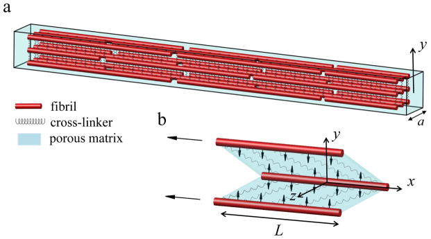
(a) The finite element model consists of staggered fibrils (red rods) interconnected with interfibrillar-linkers (springs) placed in a porous medium (cyan). The coordinate system is placed at the center of the model with x-axis directed along the fibril orientation, and y-axis perpendicular to it. (b) Under tensile loading, interfibrillar-linkers exert a compressive force to the biphasic medium (vertical arrows) and cause the fluid to flow radially outward from the encapsulated matrix. The aspect ratio in the figure is not in scale.
Table 1.
Definitions and values for symbols used in the model.
| Symbol | Definition | Value | Reference |
|---|---|---|---|
| L | fibril length | 100 μm | [25] |
| Ef | fibril Young’s modulus | 1.5 GPa | [25,42] |
| νf, νm | fibril and matrix Poisson’s ratio | 0.3 | [42] |
| Gm | matrix shear modulus | 0.1 MPa | [5,8,40,41] |
| df | fibril center–to–center spacing | 300 nm | [25] |
| Rf | fibril radius | 100 nm | [25] |
| k | matrix permeability | 3.08e-14 m4/Ns | [8] |
| n | matrix porosity | 2/3 | [8,43] |
The third component, the ECM, is modeled as a biphasic porous material that is saturated with fluid and is coherently bonded to the fibrils. By applying mechanical loading to the ECM, a fluid pressure gradient is created resulting in movement of the fluid. Darcy’s Law was applied to connect the fluid flow velocity to the pressure gradient in the ECM:
| (1) |
In equation 1, V⃗ is the fluid velocity field (m/sec), P is the fluid pressure (Pa), k is the ECM permeability (m4/Ns), and n is the matrix porosity, defined as the volume fraction of the pores in the matrix.
The fluid flow is related to the deformation of the material through the continuity equation
| (2) |
where εvol is the volumetric strain of the matrix.
In addition, the mechanical equilibrium equation should also be solved for the matrix
| (3) |
where is the effective stress and is defined by
| (4) |
σij follows the Neo-Hookean constitutive law that allows the large distortions of the ECM in our model. The mechanical properties of the ECM, such as the shear modulus (Gm) and the Poisson ratio (νm) have not been measured experimentally at this microstructural level, although by experimental fittings the matrix Young’s modulus (Em) is estimated to be 0.25 MPa [40] and 0.16 MPa [5], which for an isotropic behavior where Gm= Em/2(1−νm), results in Gm = 0.18 and 0.12MPa, respectively. Also in the previous biphasic modeling studies the estimated values of 0.1 MPa [8] and 0.385 MPa [41] are used for Gm. In this study, we assumed the shear modulus to be 0.1 MPa, which is within the range of reported values. For any initial and boundary conditions, Eqs. (2–4) can be evaluated to obtain the generated fluid pressure (P) and the fluid velocity field (Eq. 1) in the ECM.
The stiffness (K) and spacing (d) of the interfibrillar-linkers are entered in our model as a single variable (K/d) herein called the interfibrillar-linker elastic modulus. By considering the proteoglycan GAGs as the interfibrillar-linkers, following molecular simulation results [25], we use K = 0.033 N/m and d = 68 nm (with elastic modulus K/d = 0.48 MPa). For other mechanisms of the interfibrillar-linking, such as fibril bridging, we performed a parametric study and vary K/d from 0.1 to 2.4 MPa to cover all the potential strengths and densities of the interfibrillar-linking elements.
The model consists of 3-by-3 arrangement of fibrils with 100 nm gaps between the fibril ends (Fig. 1). The width of the model is a = 600 nm and the overall length is ~250 μm. The x – axis of the coordinate system is placed at the center of each fibril oriented along the fibril direction (−L/2 < x < L/2) and the y-axis origin is placed at the center of the model (−a/2 < y < a/2).
3. Finite element model results
3.1 Tendon Poisson’s ratio under tensile loading
A tensile strain of ε = 3% at the strain rate of ε̇ = 0.01sec−1 is applied (Abaqus (v. 6.13), Dassault Systemes, Providence, RI) to the ends of the model and the simulations are repeated for the interfibrillar-linking elastic moduli ranging from 0.1 to 2.4 MPa. After each increment of the tensile stretch, the volume change of the model (ΔV/V0) and the effective Poisson’s ratio (νeff which is the average of three Poisson’s ratios νyz,νxy and νxz in Fig. 1) is calculated (Fig. 2).
Fig. 2.

Predicted Poisson’s ratio for varying interfibrillar-linker elastic moduli.
| (5) |
The tensile strain applied to the ends of the tendon is transferred between the fibrils through the extension of the interfibrillar-linkers and the shearing of the matrix, due to relative sliding of the fibrils. Meanwhile the force generated in the interfibrillar-linkers pulls the neighboring fibrils relative to each other, and squeezes the encapsulated matrix leading to the volume shrinkage and fluid exudation from the tendon (Fig. 1, b). The outcome of this volume shrinkage can be observed in the evaluated Poisson’s ratio (Fig. 2). The FEM model predicts that the Poisson’s ratio is bigger than 0.5, which is indicative of a decrease in the volume (with νeff > 0.5, the volume change is negative (ΔV < 0) in Eq. 5) and fluid exudation as will be discussed in sec. 3.2. The Poisson’s ratio has a nonlinear variation with strain with large values at small strains (1–1.5%), followed by a drop for larger strains. As we will show in the theoretical modeling section (sec 4), this nonlinear behavior is the direct outcome of interconnecting role of interfibrillar-linkers in the tendon and is attributed to the relative rotation of the interfibrillar-linkers with respect to the fibrils with increasing strain.
The pressure generated in the tendon at this tensile strain is positive (Fig 3,a) and is the driving force for the fluid exudation from the core of the tendon to the surrounding medium. In our previous work [27], we found that the extension of the interfibrillar-linkers is stronger at the end of the fibrils where the relative fibril sliding is the predominant mechanism for the load transfer. In proportion to the interfibrillar-linker extension, the generated positive pressure is maximum at the fibril ends (x = 0, L/2) where fibrils are sliding (Fig. 3, a, b), and is minimum in the interior point (x = L/4) where the extension of the interfibrillar-linkers is small. This fact will result in a higher fluid velocity at the fibril ends, which is discussed in the next section.
Fig. 3.

(a) The deformed shape of a longitudinal cross-section (at y = 0, Ref to Fig. 1) at 3% strain and K/d = 0.48 MPa. The contour colors show the generated pressure in the tendon. The tendon width at two points x = 0, L/2 and x = L/4, is denoted by d1 and d2, respectively. The pressure profile along the centerline of the cross-section (b) is positive, with larger values at fibrils ends where the forces in the cross-linkers are larger. (c) The contraction in tendon width is larger at fibril ends (d1/a) than the interior point (d2/a).
In all points along the model, the width of the tendon is reduced from the initial value of (a), indicating that the interfibrillar-linkers are pulling the fibrils relative to each other and are contracting the tendon (Fig. 3, a, c). In consistency with the shear lag model [27] where the interfibrillar-linker force is larger at the fibril ends (in this case point x = L/2), the tendon shrinkage is also larger where the fibrils ends are located (d1/a which is at point x = L/2) and smaller at the other points (d2/a which is at point x = L/4).
3.2 Fluid movement
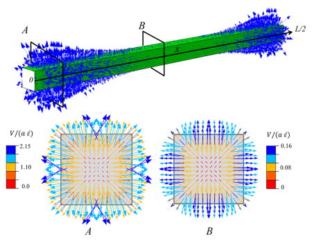
In response to the generated positive pressure and the assumption that the tendon medium maintains a zero pressure, a pressure gradient between the tendon core and the surrounding medium is generated. This pressure gradient causes the fluid to exude from the tendon and enter the medium (Fig 4). The fluid movement is directed radially from the tendon core to the outside, with the larger velocities at the outer edge of the tendon. In agreement with the pressure distribution (Fig. 3,b), the fluid flow velocity is largest on the cross-section (A) located near the fibrils ends. In this cross-section, the interfibrillar sliding is larger and creats a larger pressure in the tendon.
Fig. 4.

Fluid movement pattern at a tensile strain of 3%, with a interfibrillar-linker elastic modulus K/d = 0.48 MPa. The arrows indicate the fluid velocity field vector. Two transverse cross-sections (A) and (B) at the fibril ends (x = 0, L/2) and interior (x = L/4) points illustrate the fibril location specific fluid velocity magnitudes. The velocity magnitude is larger at cross-section (A), which is located near the fibril ends.
Next, we performed a parametric study to determine the fluid velocity exiting the tendon for varying values of interfibrillar-linker elastic moduli (Fig. 5), where the positive velocity indicates fluid exudation. As expected, fluid exudes faster for stiff interfibrillar-linkers than soft ones, and this exudation is fastest at the fibril ends.
Fig. 5.

Fluid velocity at the surface of the tendon at a tensile strain of 3%, with varying interfibrillar-linker elastic moduli. The positive values indicate fluid exudation.
The stiffness (K) and spacing (d) of the interfibrillar-linkers enter in our FEM model as a single parameter (K/d) representing the elastic modulus of the interfibrillar-linker. In the case of the GAG interfibrillar-linkers, the stiffness (K = 0.033 N/m calculated in [25]) and spacing (d = 68 nm for fibril D-period) result in K/d = 0.48 MPa which is tested in our FEM model. For the other mechanisms of the interfibrillar-linking such as the fibril bridging, the stiffness (K) depends on the radius of the fibril bridge:
| (6) |
Where R is the radius of the bridging fibril. It should be noted that, here the Young’s modulus of the bridging fibril (Ef = 1.5 GPA) is same as the aligned collagen fibrils. In this case for each elastic modulus (K/d), the radius of the bridging fibrils can be calculated based on their spacing. In Fig 6, we present radius versus spacing of the interfibrillar-linking bridges for four values of K/d = 2.40,0.48, 0.24 and 0.10 MPa tested in our model. Fig. 6 shows that in order to maintain the same K/d, by increasing the spacing between the bridging fibrils, the radius of the bridging fibrils needs to be increased correspondingly.
Fig 6.
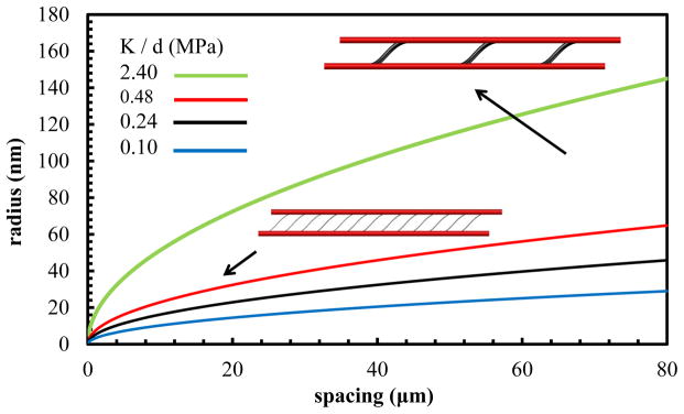
Radius versus spacing of the fibril interfibrillar-linkers for the fixed value of the interfibrillar-linker elastic modulus (K/d).
The finite element simulation incorporated fibrils interconnected by interfibrillar-linkers was able to predict the tendon volume shrinkage accompanied by fluid exudation. The Poisson’s ratio calculated by FEM was also larger than 0.5 and has a nonlinear rise and drop with the applied tensile strain, in agreement with the experimental studies. Although the FEM approach predicts the tendon behavior successfully, the micromechanical mechanism behind the variation of the Poisson’s ratio with strain can be understood more explicitly. To this end, we next considered a simple analytical model for a tendon where the matrix is a monophasic elastic matrix. With this framework, we derived the forces acting on the matrix with the theoretical shear lag model (SLM) [44]. In order to investigate the sliding between the fibrils under tensile loading, the SLM has been incorporated in the recent modeling studies [27,45–47]. We utilized the SLM to derive the forces that interfibrillar-linkers are exerting on the matrix and to see how these forces result in matrix volume changes.
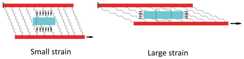
4. Theoretical 2D elastic model
Due to the periodic arrangement of fibrils in tendon (Fig. 1), two neighboring fibrils, their interconnecting interfibrillar-linkers, and an elastic monophasic matrix enclosed between the fibrils (Fig. 7) can be considered as the unit cell for the SLM. For an applied tensile stretch of ε, the displacement in each fibril is denoted by u1(x) and u2(x), and their spacing is reduced from the initial value of df to h.
Fig. 7.
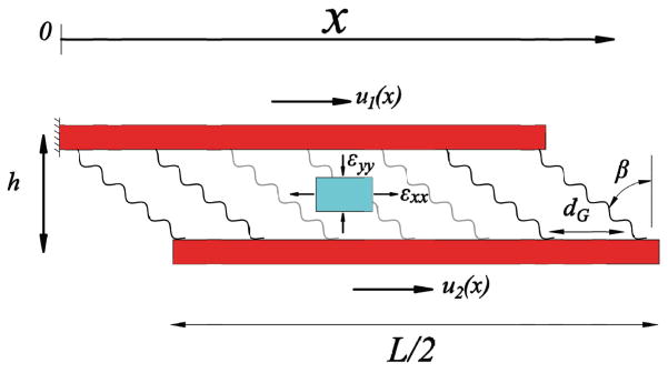
The unit cell consists of two neighboring fibrils whose interfibrillar-linkers are spaced by distance, d, and aligned at an angle β to the fibrils. For an element of the matrix (cyan), axial and transverse strains, εxx (tensile) and εyy (compressive), act on the element.
The mechanical equilibrium in each fibril is derived from the force balance of fibril elements as
| (7) |
where σ1(x) and σ2(x) are the tensile stresses in each fibril. τ(x) is the shear stress acting on fibrils and is composed of the force generated from the extension of the interfibrillar-linkers and the shear stress due to the shearing of the encapsulated matrix
| (8) |
β(x) is the rotated angle of the interfibrillar-linkers and is calculated by
| (9) |
Combining Eqs. (7,8) results in the governing equation for the system,
| (10) |
with length scales
| (11) |
Each element of the matrix experiences axial and transverse strains (Fig. 7) that are perpendicular to each other. The transverse strain εyy is a compressive strain that is caused by the transverse component of the interfibrillar-linker forces. It has a negative value and due to the periodic boundary condition is constant along the x –direction,
| (12) |
where
| (13) |
The reduced fibril spacing is related to the transverse strain by h = df(1+εyy),
| (14) |
The fibril displacements, u1(x), u2(x), interfibrillar-linker angle, β(x) and fibril spacing, h are four unknowns of the model, and correspondingly Eqs. (9, 10 and 14) give the four governing equations.
The boundary conditions to find these unknowns are,
| (15) |
In addition a periodic boundary condition (dh/dx = 0) is applied to prevent fibril rotation.
The axial strain εxx(x)is the average of the axial tensile strains in the two fibrils
| (16) |
The volume change of the matrix element and resultant Poisson’s ratio from the SLM, for the two components of the strain are defined as
| (17) |
Where V0 and ΔV are the unit cell initial volume and the volume change, respectively. The effective Poisson’s ratio is defined by equating the model to the 2D simple tensile test:
| (18) |
Therefore, the Poisson’s ratio of the SLM can be derived as
| (19) |
After solving Eqs. (9,10 and 14) with the boundary conditions of Eq. (15) using the mathematics module of Comsol Multiphysics (v. 4.4), the compressive (from Eq. (12)) and tensile strains (Eq. (16)), as well as the Poisson’s ratio (Eqs. (17–19)) for strain up to 25% were evaluated (Fig. 8). The interfibrillar-linkers elastic modulus was set to 0.48 MPa.
Fig. 8.
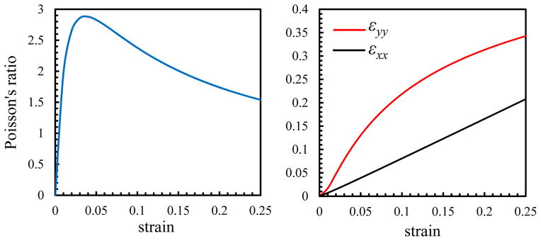
With increasing the applied strain, the tensile (εxx) and compressive (−εyy) strains increase and the Poisson’s ratio (νeff) increases rapidly at low strains prior to decreasing at higher strains.
The Poisson’s ratio depends on the trace of the strain tensor (εxx + εyy) (Eqs. (17)), and consequently, the variation of the Poisson’s ratio with strain depends on the variation of εxx and εyy independently. For small tensile strains (ε < 0.05in Fig. 8), interfibrillar-linkers are nearly perpendicular to the fibrils (β ≈ 0 in Fig. 7) and thus can exert large compressive strains (εyy) on the matrix (Eq. 12). This fact can be inferred from the faster increase in (εyy) compared to (εxx) in this region. Conversely for the large strains (ε > 0.05), the tensile strain of the matrix (εxx) has a monotonic linear increase with the applied strain, and can negate the effect of the compressive strain (εyy). The outcome of these variations can be seen in the nonlinear variation of the Poisson’s ratio with strain. Initially, as the volume shrinkage is large, the Poisson’s ratio has a rapid rise with a peak value for small strains, followed by a decrease in the volume shrinkage and a nonlinear decrease for the larger strains (Fig. 9).
Fig. 9.
For the small tensile strain, interfibrillar-linkers exert a large compressive force to the ECM and cause a significant decrease in the volume and fluid exudation, while for the large strains, the force in the interfibrillar-linkers have decreased and the ECM element is under a tensile stretch and volume expansion.
As can be observed the SLM result (Fig. 8) verifies the FEM result (Fig. 2) for the variation of the Poisson’s ratio with strain, and in addition provides a micromechanical explanation for the observed behavior. Alternatively, FEM incorporates biphasic porous matrix with realistic geometric nonlinearity such as the distortion of matrix and out of plane displacements which were ignored in the theoretical SLM.
5. Discussion
This study developed a comprehensive microstructural model to explain the experimentally observed Poisson’s ratios in tendon. A model incorporating large Poisson’s ratios and fluid movement is important to provide further mechanistic understanding of how tendon responds to load from the macro- to micro-structural levels. We showed the existence of a previously unappreciated structure-function mechanism whereby the Poisson’s ratio in tendon is affected by the strain applied and matrix properties, and together these features predict tendon volume shrinkage under tensile loading. Our FEM simulation, verified by the theoretical SLM, is capable of making the following key predictions: (1) Under tensile strain, interfibrillar-linkers pull the fibrils closer to each other generating a compressive force exerted on the encapsulated matrix, leading to the volume shrinkage and fluid exudation; (2) The Poisson’s ratio evaluated for the tendon is greater than 0.5 and has a nonlinear variation with the strain applied, in agreement with experimental observation [9]. For small strains, when the interfibrillar-linkers are still nearly perpendicular to the fibril, the Poisson’s ratio has a rapid rise to a maximum value. Conversely for the large strains, the rotation of the interfibrillar-linkers causes a decrease in the compressive force exerted to the matrix, leading to a decline in the Poisson’s ratio; (3) Under tensile force, lateral fibril contraction generates a positive fluid pressure along the length of the tendon. This contraction and positive fluid pressure plays the largest role at the points where the ends of the fibrils are located and is lowest in the interior regions; (4) The compressive force exerted by the interfibrillar-linkers to the ECM causes the enclosed fluid to exude from the tendon. The fluid flow is directed radially outward toward the surrounding medium, and has a maximum value near the ends of the fibrils.
In recent modeling works of biopolymer random networks, it has been shown that the interfibrillar-linkers interconnecting the fibers cause stress stiffening[48,49], large Poisson’s ratio [50] and water exudation [51] under stretch. While the focus of these studies is to relate the fiber realignment to the observed physical phenomena, the importance of the current work is to obtain the same behavior for the aligned fibrils in consistent with the tendon morphology. In addition, in order to explain the large Poisson’s ratio for tendon and ligaments, Reese et al., [42] proposed a microstructural model where the large Poisson’s ratio was attributed to uncrimping of the fibers under tensile loading. Our current model presents an alternative mechanism, where the initial crimped morphology of the fibrils is not required, and the contraction of the ECM and the large Poisson’s ratio is attributed to the compressive forces generated by the interfibrillar-linking elements between the fibrils. Our FEM model predicts that the Poisson’s ratio of tendon is larger than 0.5, which is indicative of volume shrinkage and has a nonlinear variation with strain with large values at small strains (1–1.5%), followed by a decrease for larger strains. Our FEM simulation shows that this nonlinear behavior, which was already verified by tensile experiment results [9], is attributed to the rotation of the interfibrillar-linkers with strain. Previous work has shown that a ~3% tensile strain results in a positive fluid pressure in the center of the tendon [52]. In agreement with our model, the pressure generated in the tendon at this tensile strain was also positive. This positive pressure was the driving force for the fluid exudation from the core of the tendon to the surrounding medium.
A potential limitation of our model is the representation of the interfibrillar sliding with uniform arrangement of the similar fibrils in the ECM. While in the current literature, the ends of the fibrils in mature tendons are not explicitly identified [33], the observed interfibrillar sliding in experimental studies [37–39] is a key mechanism that causes the fluid exudation and the large Poisson’s ratio in our model. While some studies have investigated the effect of the non-uniform staggering on the mechanical response of the elastic fiber–matrix composites [53], the poroelastic behavior still remains unexplored. Our FEM results show that fluid flow is faster near the fibril ends, in proportion to the interfibrillar sliding. For a random staggering pattern, fibril ends are located in random points along the tendon and as a result, a more uniform fluid flow with a smaller velocity can be anticipated at these points. In addition, the variation of the fibril diameter along the length [54,55] or uneven distribution of the interfibrillar linkage such as the prevalence of GAGs near the boundaries of a tendon can cause extra changes in the Poisson’s ratio and the fluid flow field. The points with larger diameters along the fibrils have bigger shear lag characteristic length (Lc in Eq. 11) and impose larger extension in the interfibrillar-linkers. Consequently, interfibrillar-linkers in those regions would exert larger compressive force to the matrix and cause faster flow of fluid compared to the other points in the model. For the purpose of this study, we assumed that in the range of the applied tensile strain (0–3%), the progressive rupture of the fibrils [47] or the detachment and attachment of the protein interfibrillar-linkers from the fibrils [26,56], have negligible effects on the mechanical response of the model and can be ignored. For the large strains (as an example, 15% for the extensor digitorum longus tendon (EDLT) [26]) the evolution of the microstructural fibrillar damage may contribute to the ultimate stress followed by a drop in the tendon stiffness, while in our FEM model, the applied tensile strain is kept between 0–3% to avoid the inevitable micromechanical failures observed in the larger strains [57]. Finally, our model incorporates a steady-state poroelastic behavior where the dynamic effects caused by the viscoelasticity of the fibrils [58,59] or the matrix [56,60] are neglected. In the viscoelastic model, faster strain rates cause larger elongation in the fibrils followed by a gradual fluid exudation and stress relaxation [61].
Future work will investigate these mechanisms, as well as the effect of the ionic exchange [62], viscoelasticity [7,60,61], collagen fiber crimp and re-alignment [10–13,42,63] and disorganization of collagen fibers [64] as they are all important factors that contribute to the overall tendon mechanical response. In addition, future studies can use this model to study the altered mechanical response in damaged, diseased and injured tendon [65–71]. In addition, future work will investigate whether the fluid flow predicted has ramifications for shear stresses that tendon cells may experience and respond to during loading [7,8,72,73]. For example fluid flow has been shown to induce changes in expression for genes involved with degradation [74], collagen remodeling [72], antifibrosis [75], ecto-ATPase activity [76] nitrous oxide (NO) production[77] and calcium signaling [73] in tendon.
In conclusion, we present a novel approach to understand tendon poroelasticity with a two-prong modeling approach incorporating both 3D finite element and analytical shear-lag models. Our study used the unique microstructure of tendon to accurately predict interfacial shear stress and fluid flow behavior for full tendon. Moreover, this model is capable of measuring and predicting the direction and velocity of fluid flow from the tissue under tensile loading and gives physical meaning to the experimental determination of non-linear Poisson’s ratios. This work not only presents a new microstructural understanding of tendon behavior to the field, but may also serve as a guide for future models and experimental approaches in biomaterial design and tissue engineering for tendon.
Acknowledgments
This study was supported by the National Institute of Biomedical Imaging and Bioengineering of the National Institutes of Health under Award Number R01EB017753 and the US National Science Foundation Grant CMMI-1312392. (to V.B.S.), by the National Institutes of Health Grant T32 AR556680, and the US National Science Foundation GRFP (to L.J.S).
Footnotes
Publisher's Disclaimer: This is a PDF file of an unedited manuscript that has been accepted for publication. As a service to our customers we are providing this early version of the manuscript. The manuscript will undergo copyediting, typesetting, and review of the resulting proof before it is published in its final citable form. Please note that during the production process errors may be discovered which could affect the content, and all legal disclaimers that apply to the journal pertain.
References
- 1.Thielke RJ, Vanderby R, Jr, Grood ES. Volumetric changes in ligaments under tension. Am Soc Mech Eng Bioeng Div Publ BED. 1995;29:197–8. [Google Scholar]
- 2.Hannafin JA, Arnoczky SP. Effect of cyclic and static tensile loading on water content and solute diffusion in canine flexor tendons: An in Vitro study. J Orthop Res. 1994;12:350–6. doi: 10.1002/jor.1100120307. [DOI] [PubMed] [Google Scholar]
- 3.Han S, Gemmell SJ, Helmer KG, Grigg P, Wellen JW, Hoffman AH, et al. Changes in ADC Caused by Tensile Loading of Rabbit Achilles Tendon: Evidence for Water Transport. J Magn Reson. 2000;144:217–27. doi: 10.1006/jmre.2000.2075. [DOI] [PubMed] [Google Scholar]
- 4.Hewitt J, Guilak F, Glisson R, Vail TP. Regional material properties of the human hip joint capsule ligaments. J Orthop Res. 2001;19:359–64. doi: 10.1016/S0736-0266(00)00035-8. [DOI] [PubMed] [Google Scholar]
- 5.Lynch HA, Johannessen W, Wu JP, Jawa A, Elliott DM. Effect of Fiber Orientation and Strain Rate on the Nonlinear Uniaxial Tensile Material Properties of Tendon. J Biomech Eng. 2003;125:726–31. doi: 10.1115/1.1614819. [DOI] [PubMed] [Google Scholar]
- 6.Reese SP, Weiss JA. Tendon Fascicles Exhibit a Linear Correlation Between Poisson’s Ratio and Force During Uniaxial Stress Relaxation. J Biomech Eng. 2013;135:034501–034501. doi: 10.1115/1.4023134. [DOI] [PMC free article] [PubMed] [Google Scholar]
- 7.Yin L, Elliott DM. A biphasic and transversely isotropic mechanical model for tendon:: application to mouse tail fascicles in uniaxial tension. J Biomech. 2004;37:907–16. doi: 10.1016/j.jbiomech.2003.10.007. [DOI] [PubMed] [Google Scholar]
- 8.Lavagnino M, Arnoczky SP, Kepich E, Caballero O, Haut RC. A finite element model predicts the mechanotransduction response of tendon cells to cyclic tensile loading. Biomech Model Mechanobiol. 2008;7:405–16. doi: 10.1007/s10237-007-0104-z. [DOI] [PubMed] [Google Scholar]
- 9.Swedberg AM, Reese SP, Maas SA, Ellis BJ, Weiss JA. Continuum description of the Poisson’s ratio of ligament and tendon under finite deformation. J Biomech. n.d doi: 10.1016/j.jbiomech.2014.05.011. [DOI] [PMC free article] [PubMed] [Google Scholar]
- 10.Miller KS, Connizzo BK, Soslowsky LJ. Collagen Fiber Re-Alignment in a Neonatal Developmental Mouse Supraspinatus Tendon Model. Ann Biomed Eng. 2012;40:1102–10. doi: 10.1007/s10439-011-0490-3. [DOI] [PMC free article] [PubMed] [Google Scholar]
- 11.Miller KS, Connizzo BK, Feeney E, Soslowsky LJ. Characterizing local collagen fiber re-alignment and crimp behavior throughout mechanical testing in a mature mouse supraspinatus tendon model. J Biomech. 2012;45:2061–5. doi: 10.1016/j.jbiomech.2012.06.006. [DOI] [PMC free article] [PubMed] [Google Scholar]
- 12.Connizzo BK, Sarver JJ, Iozzo RV, Birk DE, Soslowsky LJ. Effect of Age and Proteoglycan Deficiency on Collagen Fiber Re-Alignment and Mechanical Properties in Mouse Supraspinatus Tendon. J Biomech Eng. 2013;135:021019–021019. doi: 10.1115/1.4023234. [DOI] [PMC free article] [PubMed] [Google Scholar]
- 13.Miller KS, Connizzo BK, Feeney E, Tucker JJ, Soslowsky LJ. Examining Differences in Local Collagen Fiber Crimp Frequency Throughout Mechanical Testing in a Developmental Mouse Supraspinatus Tendon Model. J Biomech Eng. 2012;134:041004–041004. doi: 10.1115/1.4006538. [DOI] [PMC free article] [PubMed] [Google Scholar]
- 14.Ansorge HL, Adams S, Jawad AF, Birk DE, Soslowsky LJ. Mechanical property changes during neonatal development and healing using a multiple regression model. J Biomech. 2012;45:1288–92. doi: 10.1016/j.jbiomech.2012.01.030. [DOI] [PMC free article] [PubMed] [Google Scholar]
- 15.Lujan TJ, Underwood CJ, Henninger HB, Thompson BM, Weiss JA. Effect of dermatan sulfate glycosaminoglycans on the quasi-static material properties of the human medial collateral ligament. J Orthop Res. 2007;25:894–903. doi: 10.1002/jor.20351. [DOI] [PubMed] [Google Scholar]
- 16.Fessel G, Snedeker JG. Evidence against proteoglycan mediated collagen fibril load transmission and dynamic viscoelasticity in tendon. Matrix Biol. 2009;28:503–10. doi: 10.1016/j.matbio.2009.08.002. [DOI] [PubMed] [Google Scholar]
- 17.Provenzano PP, Vanderby R., Jr Collagen fibril morphology and organization: Implications for force transmission in ligament and tendon. Matrix Biol. 2006;25:71–84. doi: 10.1016/j.matbio.2005.09.005. [DOI] [PubMed] [Google Scholar]
- 18.Cribb AM, Scott JE. Tendon response to tensile stress: an ultrastructural investigation of collagen:proteoglycan interactions in stressed tendon. J Anat. 1995;187:423–8. [PMC free article] [PubMed] [Google Scholar]
- 19.ESJ, ROC, WHE Proteoglycan-collagen arrangements in developing rat tail tendon. [accessed September 17, 2014];An electron microscopical and biochemical investigation. 1981 doi: 10.1042/bj1950573. http://www.biochemj.org/bj/195/bj1950573.htm. [DOI] [PMC free article] [PubMed]
- 20.Scott JE, Hughes EW. Proteoglycan-Collagen Relationships in Developing Chick and Bovine Tendons. Influence of the Physiological Environment Connect Tissue Res. 1986;14:267–78. doi: 10.3109/03008208609017470. [DOI] [PubMed] [Google Scholar]
- 21.Vogel KG, Trotter JA. The Effect of Proteoglycans on the Morphology of Collagen Fibrils Formed In Vitro. Coll Relat Res. 1987;7:105–14. doi: 10.1016/S0174-173X(87)80002-X. [DOI] [PubMed] [Google Scholar]
- 22.Svensson L, Narlid I, Oldberg A. Fibromodulin and lumican bind to the same region on collagen type I fibrils. FEBS Lett. 2000;470:178–82. doi: 10.1016/S0014-5793(00)01314-4. [DOI] [PubMed] [Google Scholar]
- 23.Fransson LA. Interaction between dermatan sulphate chains I. Affinity chromatography of copolymeric galactos-aminoglycans on dermatan sulphate-substituted agarose. Biochim Biophys Acta BBA - Gen Subj. 1976;437:106–15. doi: 10.1016/0304-4165(76)90351-2. [DOI] [PubMed] [Google Scholar]
- 24.Fransson L-Å, Cöster L. Interaction between dermatan sulphate chains II. Structural studies on aggregating glycan chains and oligosaccharides with affinity for dermatan sulphate-substituted agarose. Biochim Biophys Acta BBA - Gen Subj. 1979;582:132–44. doi: 10.1016/0304-4165(79)90296-4. [DOI] [PubMed] [Google Scholar]
- 25.Redaelli A, Vesentini S, Soncini M, Vena P, Mantero S, Montevecchi FM. Possible role of decorin glycosaminoglycans in fibril to fibril force transfer in relative mature tendons—a computational study from molecular to microstructural level. J Biomech. 2003;36:1555–69. doi: 10.1016/S0021-9290(03)00133-7. [DOI] [PubMed] [Google Scholar]
- 26.Ciarletta P, Amar MB. A finite dissipative theory of temporary interfibrillar bridges in the extracellular matrix of ligaments and tendons. J R Soc Interface. 2009;6:909–24. doi: 10.1098/rsif.2008.0487. [DOI] [PMC free article] [PubMed] [Google Scholar]
- 27.Ahmadzadeh H, Connizzo BK, Freedman BR, Soslowsky LJ, Shenoy VB. Determining the contribution of glycosaminoglycans to tendon mechanical properties with a modified shear-lag model. J Biomech. 2013;46:2497–503. doi: 10.1016/j.jbiomech.2013.07.008. [DOI] [PMC free article] [PubMed] [Google Scholar]
- 28.Fessel G, Snedeker JG. Equivalent stiffness after glycosaminoglycan depletion in tendon — an ultra-structural finite element model and corresponding experiments. J Theor Biol. 2011;268:77–83. doi: 10.1016/j.jtbi.2010.10.007. [DOI] [PubMed] [Google Scholar]
- 29.Lujan TJ, Underwood CJ, Jacobs NT, Weiss JA. Contribution of glycosaminoglycans to viscoelastic tensile behavior of human ligament. J Appl Physiol. 2009;106:423–31. doi: 10.1152/japplphysiol.90748.2008. [DOI] [PMC free article] [PubMed] [Google Scholar]
- 30.Screen HRC, Shelton JC, Chhaya VH, Kayser MV, Bader DL, Lee DA. The Influence of Noncollagenous Matrix Components on the Micromechanical Environment of Tendon Fascicles. Ann Biomed Eng. 2005;33:1090–9. doi: 10.1007/s10439-005-5777-9. [DOI] [PubMed] [Google Scholar]
- 31.Palombo F, Winlove CP, Edginton RS, Green E, Stone N, Caponi S, et al. Biomechanics of fibrous proteins of the extracellular matrix studied by Brillouin scattering. J R Soc Interface. 2014;11:20140739. doi: 10.1098/rsif.2014.0739. [DOI] [PMC free article] [PubMed] [Google Scholar]
- 32.Henninger HB, Underwood CJ, Romney SJ, Davis GL, Weiss JA. Effect of elastin digestion on the quasi-static tensile response of medial collateral ligament. J Orthop Res. 2013;31:1226–33. doi: 10.1002/jor.22352. [DOI] [PMC free article] [PubMed] [Google Scholar]
- 33.Starborg T, Kalson NS, Lu Y, Mironov A, Cootes TF, Holmes DF, et al. Using transmission electron microscopy and 3View to determine collagen fibril size and three-dimensional organization. Nat Protoc. 2013;8:1433–48. doi: 10.1038/nprot.2013.086. [DOI] [PMC free article] [PubMed] [Google Scholar]
- 34.Berenguer F, Bean RJ, Bozec L, Vila-Comamala J, Zhang F, Kewish CM, et al. Coherent X-Ray Imaging of Collagen Fibril Distributions within Intact Tendons. Biophys J. 2014;106:459–66. doi: 10.1016/j.bpj.2013.12.016. [DOI] [PMC free article] [PubMed] [Google Scholar]
- 35.Starborg T, Lu Y, Huffman A, Holmes DF, Kadler KE. Electron microscope 3D reconstruction of branched collagen fibrils in vivo. Scand J Med Sci Sports. 2009;19:547–52. doi: 10.1111/j.1600-0838.2009.00907.x. [DOI] [PubMed] [Google Scholar]
- 36.Watanabe T, Imamura Y, Hosaka Y, Ueda H, Takehana K. Graded Arrangement of Collagen Fibrils in the Equine Superficial Digital Flexor Tendon. Connect Tissue Res. 2007;48:332–7. doi: 10.1080/03008200701692800. [DOI] [PubMed] [Google Scholar]
- 37.Rigozzi S, Stemmer A, Muller R, Snedeker JG. Mechanical response of individual collagen fibrils in loaded tendon as measured by atomic force microscopy. J Struct Biol. 2011;176:9–15. doi: 10.1016/j.jsb.2011.07.002. [DOI] [PubMed] [Google Scholar]
- 38.Screen HRC, Bader DL, Lee DA, Shelton JC. Local Strain Measurement within Tendon. Strain. 2004;40:157–63. doi: 10.1111/j.1475-1305.2004.00164.x. [DOI] [Google Scholar]
- 39.Szczesny SE, Elliott DM. Interfibrillar shear stress is the loading mechanism of collagen fibrils in tendon. Acta Biomater. n.d doi: 10.1016/j.actbio.2014.01.032. [DOI] [PMC free article] [PubMed] [Google Scholar]
- 40.Ault HK, Hoffman AH. A Composite Micromechanical Model for Connective Tissues: Part II— Application to Rat Tail Tendon and Joint Capsule. J Biomech Eng. 1992;114:142–6. doi: 10.1115/1.2895438. [DOI] [PubMed] [Google Scholar]
- 41.Adeeb S, Ali A, Shrive N, Frank C, Smith D. Modelling the Behaviour of Ligaments: A Technical Note. Comput Methods Biomech Biomed Engin. 2004;7:33–42. doi: 10.1080/10255840310001637266. [DOI] [PubMed] [Google Scholar]
- 42.Reese SP, Maas SA, Weiss JA. Micromechanical models of helical superstructures in ligament and tendon fibers predict large Poisson’s ratios. J Biomech. 2010;43:1394–400. doi: 10.1016/j.jbiomech.2010.01.004. [DOI] [PMC free article] [PubMed] [Google Scholar]
- 43.MBR Tendons and ligaments--an overview. Histol Histopathol. 1997;12:1135–44. [PubMed] [Google Scholar]
- 44.Cox HL. The elasticity and strength of paper and other fibrous materials. Br J Appl Phys. 1952;3:72. doi: 10.1088/0508-3443/3/3/302. [DOI] [Google Scholar]
- 45.Szczesny SE, Elliott DM. Interfibrillar shear stress is the loading mechanism of collagen fibrils in tendon. Acta Biomater. 2014;10:2582–90. doi: 10.1016/j.actbio.2014.01.032. [DOI] [PMC free article] [PubMed] [Google Scholar]
- 46.Szczesny SE, Elliott DM. Incorporating plasticity of the interfibrillar matrix in shear lag models is necessary to replicate the multiscale mechanics of tendon fascicles. J Mech Behav Biomed Mater. 2014;40:325–38. doi: 10.1016/j.jmbbm.2014.09.005. [DOI] [PMC free article] [PubMed] [Google Scholar]
- 47.Pensalfini M, Duenwald-Kuehl S, Kondratko-Mittnacht J, Lakes R, Vanderby R. Evaluation of global load sharing and shear-lag models to describe mechanical behavior in partially lacerated tendons. J Biomech Eng. 2014;136:091006. doi: 10.1115/1.4027714. [DOI] [PMC free article] [PubMed] [Google Scholar]
- 48.Stein AM, Vader DA, Weitz DA, Sander LM. The micromechanics of three-dimensional collagen-I gels. Complexity. 2011;16:22–8. doi: 10.1002/cplx.20332. [DOI] [Google Scholar]
- 49.Huisman EM, van Dillen T, Onck PR, Van der Giessen E. Three-Dimensional Cross-Linked F-Actin Networks: Relation between Network Architecture and Mechanical Behavior. Phys Rev Lett. 2007;99:208103. doi: 10.1103/PhysRevLett.99.208103. [DOI] [PubMed] [Google Scholar]
- 50.Stylianopoulos T, Barocas VH. Volume-averaging theory for the study of the mechanics of collagen networks. Comput Methods Appl Mech Eng. 2007;196:2981–90. doi: 10.1016/j.cma.2006.06.019. [DOI] [Google Scholar]
- 51.Brown AEX, Litvinov RI, Discher DE, Purohit PK, Weisel JW. Multiscale Mechanics of Fibrin Polymer: Gel Stretching with Protein Unfolding and Loss of Water. Science. 2009;325:741–4. doi: 10.1126/science.1172484. [DOI] [PMC free article] [PubMed] [Google Scholar]
- 52.Chen C, McCabe RP, Vanderby R. Two electrokinetic phenomena in rabbit patellar tendon: Pressure and voltage. ASME-Publ-BED. 1995;29:31–31. [Google Scholar]
- 53.Zhang ZQ, Liu B, Huang Y, Hwang KC, Gao H. Mechanical properties of unidirectional nanocomposites with non-uniformly or randomly staggered platelet distribution. J Mech Phys Solids. 2010;58:1646–60. doi: 10.1016/j.jmps.2010.07.004. [DOI] [Google Scholar]
- 54.Trotter JA, Kadler KE, Holmes DF. Echinoderm collagen fibrils grow by surface-nucleation-andpropagation from both centers and ends. J Mol Biol. 2000;300:531–40. doi: 10.1006/jmbi.2000.3879. [DOI] [PubMed] [Google Scholar]
- 55.Parkinson J, Kadler KE, Brass A. Simple physical model of collagen fibrillogenesis based on diffusion limited aggregation. J Mol Biol. 1995;247:823–31. doi: 10.1016/S0022-2836(05)80157-3. [DOI] [PubMed] [Google Scholar]
- 56.Ciarletta P, Micera S, Accoto D, Dario P. A novel microstructural approach in tendon viscoelastic modelling at the fibrillar level. J Biomech. 2006;39:2034–42. doi: 10.1016/j.jbiomech.2005.06.025. [DOI] [PubMed] [Google Scholar]
- 57.Provenzano PP, Heisey D, Hayashi K, Lakes R, Ray Vanderby J. Subfailure damage in ligament: a structural and cellular evaluation. J Appl Physiol. 2002;92:362–71. doi: 10.1152/jappl.2002.92.1.362. [DOI] [PubMed] [Google Scholar]
- 58.Gautieri A, Vesentini S, Redaelli A, Buehler MJ. Viscoelastic properties of model segments of collagen molecules. Matrix Biol. 2012;31:141–9. doi: 10.1016/j.matbio.2011.11.005. [DOI] [PubMed] [Google Scholar]
- 59.Shen ZL, Kahn H, Ballarini R, Eppell SJ. Viscoelastic Properties of Isolated Collagen Fibrils. Biophys J. 2011;100:3008–15. doi: 10.1016/j.bpj.2011.04.052. [DOI] [PMC free article] [PubMed] [Google Scholar]
- 60.Puxkandl R, Zizak I, Paris O, Keckes J, Tesch W, Bernstorff S, et al. Viscoelastic properties of collagen: synchrotron radiation investigations and structural model. Philos Trans R Soc Lond B Biol Sci. 2002;357:191–7. doi: 10.1098/rstb.2001.1033. [DOI] [PMC free article] [PubMed] [Google Scholar]
- 61.Clemmer J, Liao J, Davis D, Horstemeyer MF, Williams LN. A mechanistic study for strain rate sensitivity of rabbit patellar tendon. J Biomech. 2010;43:2785–91. doi: 10.1016/j.jbiomech.2010.06.009. [DOI] [PMC free article] [PubMed] [Google Scholar]
- 62.Buckley MR, Sarver JJ, Freedman BR, Soslowsky LJ. The dynamics of collagen uncrimping and lateral contraction in tendon and the effect of ionic concentration. J Biomech. 2013;46:2242–9. doi: 10.1016/j.jbiomech.2013.06.029. [DOI] [PMC free article] [PubMed] [Google Scholar]
- 63.Lake SP, Miller KS, Elliott DM, Soslowsky LJ. Effect of fiber distribution and realignment on the nonlinear and inhomogeneous mechanical properties of human supraspinatus tendon under longitudinal tensile loading. J Orthop Res. 2009;27:1596–602. doi: 10.1002/jor.20938. [DOI] [PMC free article] [PubMed] [Google Scholar]
- 64.Thomopoulos S, Genin GM, Galatz LM. The development and morphogenesis of the tendon-to-bone insertion What development can teach us about healing. J Musculoskelet Neuronal Interact. 2010;10:35–45. [PMC free article] [PubMed] [Google Scholar]
- 65.Freedman BR, Sarver JJ, Buckley MR, Voleti PB, Soslowsky LJ. Biomechanical and structural response of healing Achilles tendon to fatigue loading following acute injury. J Biomech. 2014;47:2028–34. doi: 10.1016/j.jbiomech.2013.10.054. [DOI] [PMC free article] [PubMed] [Google Scholar]
- 66.Connizzo BK, Bhatt PR, Liechty KW, Soslowsky LJ. Diabetes alters mechanical properties and collagen fiber re-alignment in multiple mouse tendons. Ann Biomed Eng. 2014;42:1880–8. doi: 10.1007/s10439-014-1031-7. [DOI] [PMC free article] [PubMed] [Google Scholar]
- 67.Jepsen KJ, Wu F, Peragallo JH, Paul J, Roberts L, Ezura Y, et al. A syndrome of joint laxity and impaired tendon integrity in lumican- and fibromodulin-deficient mice. J Biol Chem. 2002;277:35532–40. doi: 10.1074/jbc.M205398200. [DOI] [PubMed] [Google Scholar]
- 68.Beynnon BD, Proffer D, Drez DJ, Stankewich CJ, Johnson RJ. Biomechanical assessment of the healing response of the rabbit patellar tendon after removal of its central third. Am J Sports Med. 1995;23:452–7. doi: 10.1177/036354659502300414. [DOI] [PubMed] [Google Scholar]
- 69.Arya S, Kulig K. Tendinopathy alters mechanical and material properties of the Achilles tendon. J Appl Physiol Bethesda Md 1985. 2010;108:670–5. doi: 10.1152/japplphysiol.00259.2009. [DOI] [PubMed] [Google Scholar]
- 70.Abboud JA, Beason DP, Soslowsky LJ. Emerging ideas: the effect of hypercholesterolemia on tendons. Clin Orthop. 2012;470:317–20. doi: 10.1007/s11999-010-1709-6. [DOI] [PMC free article] [PubMed] [Google Scholar]
- 71.Thorpe CT, Riley GP, Birch HL, Clegg PD, Screen HRC. Effect of fatigue loading on structure and functional behaviour of fascicles from energy-storing tendons. Acta Biomater. 2014;10:3217–24. doi: 10.1016/j.actbio.2014.04.008. [DOI] [PubMed] [Google Scholar]
- 72.Maeda T, Sakabe T, Sunaga A, Sakai K, Rivera AL, Keene DR, et al. Conversion of Mechanical Force into TGF-β-Mediated Biochemical Signals. Curr Biol. 2011;21:933–41. doi: 10.1016/j.cub.2011.04.007. [DOI] [PMC free article] [PubMed] [Google Scholar]
- 73.Maeda E, Hagiwara Y, Wang JH-C, Ohashi T. A new experimental system for simultaneous application of cyclic tensile strain and fluid shear stress to tenocytes in vitro. Biomed Microdevices. 2013;15:1067–75. doi: 10.1007/s10544-013-9798-0. [DOI] [PubMed] [Google Scholar]
- 74.Archambault JM, Elfervig-Wall MK, Tsuzaki M, Herzog W, Banes AJ. Rabbit tendon cells produce MMP-3 in response to fluid flow without significant calcium transients. J Biomech. 2002;35:303–9. doi: 10.1016/s0021-9290(01)00217-2. [DOI] [PubMed] [Google Scholar]
- 75.Fong KD, Trindade MC, Wang Z, Nacamuli RP, Pham H, Fang TD, et al. Microarray Analysis of Mechanical Shear Effects on Flexor Tendon Cells. Plast Reconstr Surg. 2005;116:1393–404. doi: 10.1097/01.prs.0000182345.86453.4f. [DOI] [PubMed] [Google Scholar]
- 76.Tsuzaki M, Bynum D, Almekinders L, Faber J, Banes Aj. Mechanical loading stimulates ecto-ATPase activity in human tendon cells. J Cell Biochem. 2005;96:117–25. doi: 10.1002/jcb.20491. [DOI] [PubMed] [Google Scholar]
- 77.Van Griensven M, Zeichen J, Skutek M, Barkhausen T, Krettek C, Bosch U. Cyclic mechanical strain induces NO production in human patellar tendon fibroblasts – a possible role for remodelling and pathological transformation. Exp Toxicol Pathol. 2003;54:335–8. doi: 10.1078/0940-2993-00268. [DOI] [PubMed] [Google Scholar]