

Abstract
When Segré and Silberberg in 1961 witnessed particles in a laminar pipe flow congregating at an annulus in the pipe, scientists were perplexed and spent decades learning why such behavior occurred, finally understanding that it was caused by previously unknown forces on particles in an inertial flow. The advent of microfluidics opened a new realm of possibilities for inertial focusing in the processing of biological fluids and cellular suspensions and created a field that is now rapidly expanding. Over the past five years, inertial focusing has enabled high-throughput, simple, and precise manipulation of bodily fluids for a myriad of applications in point-of-care and clinical diagnostics. This review describes the theoretical developments that have made the field of inertial focusing what it is today and presents the key applications that will make inertial focusing a mainstream technology in the future.
Keywords: high throughput, particle separation, label-free cell separation, biofluid processing, hydrodynamic lift, applied physics
INTRODUCTION
The ability to precisely control the motion of cells on the microscale is essential for the utility of microfluidics in biological research and health care. Over the past 20 years, microfluidic technology development has focused primarily on techniques to achieve this control, including, for example, dielectrophoresis, hydrophoresis, magnetophoresis, and inertial focusing (1, 2). Among these promising technologies, inertial focusing has gained significant attention since its first use in microfluidics in 2007, as it offers precise control of particles through the use of purely hydrodynamic interactions at high speeds at which traditional microfluidic principles no longer apply (3).
Microfluidic technologies, with micrometer-scale channel dimensions comparable in length scale to the target cells, emerged two decades ago as a potential solution for processing various bodily fluids. There are a myriad of passive and active microfluidic technologies already available for separating cells. Passive techniques are used to manipulate and separate cells on the microscale without an externally applied force or field. These passive techniques include hydrophoresis (4), deterministic lateral displacement (5), and gravitational methods (6). Both hydrophoresis and deterministic lateral displacement utilize low-Reynolds-number behaviors, based upon the fluid and particles interacting with structures along a channel, to cause the separation of particles by size.
Hydrophoresis begins with the generation of transverse pressure gradients in a microchannel with slanted obstacles. This pressure gradient then sets up a secondary flow, which can be used to guide and separate particles. Hydrophoresis can also be used in conjunction with Weir-type filters that allow only particles below a certain size range to pass (7–9). Deterministic lateral displacement works on a similar particle–structure interaction principle. In the absence of structures, a particle flowing through a straight channel at low Reynolds number will follow the streamline at which its center of mass is located. When the particle interacts with an obstacle, the way in which it moves around the obstacle is dependent on this same center-of-mass streamline. As the particle passes the obstacle, its center of mass crosses streamlines as it rolls along the surface of the obstacle. A larger particle will, therefore, cross more streamlines, as its center of mass will end up farther from the obstacle owing to steric effects. If obstacles are arrayed at a small angle to the direction of the flow, some particles will always pass in the same direction around each obstacle, whereas others will alternatively pass in either direction depending on their initial positions. This creates a critical diameter above which particles will move along the angled array of obstacles and below which particles will essentially pass straight through the array. This critical particle diameter can be calculated and adjusted based upon the design parameters of the array (10, 11).
Gravitational separation works on the basic principle that particles of different sizes will have different terminal velocities in a gravitational field because Stokes’ drag and buoyancy forces scale with diameter and volume, respectively. Although gravitational separation uses an external field and operates much like the other field-flow-fractionation (FFF) techniques, it is considered passive because there is no actively applied or modulated field.
Some of the active microfluidic techniques that have been developed include dielectrophoresis (12–14), acoustophoresis (15), and magnetophoresis (16). These techniques are all considered FFF techniques—that is, techniques in which particles within a flow are moving at relatively uniform velocities, and then a field (electrical, magnetic, or acoustic) is applied, causing the separation of particles by size or other properties. Dielectrophoretic forces are dependent not only on the size of the objects but also on their electrical properties and the electrical properties of the surrounding fluid as well as the properties of the electrical field (14, 17). Acoustophoresis uses standing sonic waves to generate, on a body suspended in a fluid, a pressure force proportional to the particle size. Magnetophoresis relies on the use of magnetic beads, which can be attached to cells of interest through antibody–antigen interactions. The advantage of using magnetophoresis over the other FFF techniques is that biological samples have minimal naturally occurring magnetic properties, leading to excellent separation sensitivity. Several reviews comparing these different separation modalities are available in the literature (2, 18, 19). In general, these techniques rely on the low-Reynolds-number nature of a fluid flow to allow the separation technique to occur in an ordered and predictable fashion. Although all of these concepts have proven successful for a variety of biological applications, their typically low throughput has been a principal impediment to their widespread use and application to rare-cell isolation.
Being able to process real world–sized samples efficiently has been a major challenge since the beginning of the field of microfluidics (20). Is it possible to take advantage of microfluidic sensitivity without the limitation on throughput? The solution to this problem may well lie in a regime of inertial fluid dynamics on the microscale in which suspended particles migrate across streamlines to predictable equilibrium positions within a flow. Reliance on the inertia of the fluid in the system rather than on limiting its effects, as is normally done in microfluidics, results in a significantly higher throughput.
In this review, we discuss the fundamental theory behind the phenomenon of inertial focusing and its applications in the biomedical sciences. The ability to separate cells based upon size is examined for the different microfluidic architectures that have been developed for taking advantage of inertial focusing. We distinguish particles (rigid bodies) from cells in terms of their dynamics and equilibrium behaviors. As the field of inertial focusing is expanding rapidly and still developing, the reader should be aware that this review presents only the current state of knowledge. Areas of incomplete knowledge are highlighted in order to engage further discovery and theoretical development.
ORIGINS
The earliest description of the phenomenon known as inertial focusing was by Segré & Silberberg (21) in 1961. Their experiments using a cylindrical pipe (~1-cm diameter) found that particles (~1-mm diameter) migrated to an annulus, with a mean radius of ~0.6 times the pipe radius, between the centerline of the pipe and the pipe wall. This phenomenon is known as the tubular pinch effect. An analysis of the fluid dynamics equations of motion, or the Navier–Stokes equations, determined that the cross-streamline motion of particles was due to inertia-based effects because the Stokes’ equation (low-Reynolds-number flows) was always symmetric and therefore particles were unable to cross streamlines in such a flow lacking inertial effects. Here, channel Reynolds number, ReC, is defined as the ratio of inertial to viscous effects in a channel flow,
| (1) |
where ρ is the fluid density, μ is the fluid viscosity, UMax is the maximum velocity of the fluid, and Dh is the hydraulic diameter of the channel, defined as Dh = 2hw/(h + w), where h and w are the height and width, respectively, of the channel cross section. The key to the theoretical development around inertial focusing was understanding that correctly describing the behavior requires the inclusion of the inertial terms of the Navier–Stokes equations because without inertia, lateral migration across streamlines would not be possible. This important fact is what enables the control of particle positions within a channel using inertial microfluidics.
The discovery of the tubular pinch effect motivated attempts by numerous theorists to explain this motion, as the theories of that time for lateral motion of particles could not explain the experimental results. One of these theories, proposed by Rubinow & Keller (22) in 1961, had recently provided a theoretical explanation for the Magnus force, which is lift on a rotating object in a uniform flow, but it could not explain the Segré and Silberberg equilibrium position because the Magnus force was always directed toward the center of the pipe in the context of the Segré and Silberberg experiments.
In 2004, Matas et al. (23) provided a comprehensive historical summary of the development of the modern understanding of inertial focusing. Their report was based on Feng and colleagues’ (24) work and is briefly summarized here: Two major advancements since the initial attempts to explain the Segré and Silberberg results have contributed to the development of the current understanding of inertial lift. First, in 1965, Saffman (25) proposed a theoretical force independent of particle rotation and due solely to the difference in fluid velocity on either side of a particle in a linear shear flow. This force was also found to be dependent on the difference in velocity between the particle and the undisturbed velocity profile at the same position within the flow (sometimes referred to as lag or slip velocity). At the time, this finding helped justify some of the experimental results for sedimenting particles in flows (26, 27), but it could not account for the equilibrium positions of the neutrally buoyant particles of Segré and Silberberg.
The second major contribution to the study of inertial focusing occurred in the mid-1970s when Ho & Leal (28) and Vasseur & Cox (29) applied similar analytical techniques to quadratic flows and found a force directed toward the walls of a channel proportional to the variation in shear rate. This shear gradient lift force coupled with a wall interaction–induced repulsive force accurately predicted the Segré and Silberberg equilibrium position. These studies determined that the shear gradient lift force is only one of three contributing effects but that it is by far the most dominant: It is a single order of magnitude greater than the Saffman lift force described above and three orders of magnitude greater than a rotation-induced lift force (28). At that point in the history of inertial focusing, this discovery was merely a scientific curiosity, but that changed with the advent of microfluidics (see below).
In common inertial focusing applications, it is generally accepted that the Saffman and rotational forces can be ignored; however, these forces must be included in nonneutrally buoyant cases, especially in vertical flows (aligned with gravity), and may have implications for the dynamics of inertial focusing behavior (30). In this review, as cells are near the density of normal media (or buffer solutions) and microfluidic devices are most commonly run perpendicular to gravity, we assume that the dominant effects are those of the shear gradient lift force and the wall interaction force, which are most often summed and called inertial lift.
Perhaps the most significant advancement of inertial focusing was sparked by the development of microfluidics. The intriguing results developed by historical fluid mechanics were now applicable to the control of cells as they flowed through microchannels. The first experimental results in a microfluidic architecture with a rectilinear channel were generated in 2007 by Di Carlo et al. (3) and are depicted in Figure 1 with other early observations of inertial focusing in microfluidics.
Figure 1.

Early observations of inertial focusing in different microfluidic geometries. (a, top left) Schematic and image of inertial focusing in an asymmetrically curved microchannel. (bottom left) Longitudinal ordering in straight channels with the spacing measured to be multiples of 3.6 times the particle diameter at the same cross-sectional equilibrium positions. ACF is an autocorrelation function used to measure the spacing or lag between particles in an image (3). (right) Particle Reynolds number (ReP) effects in both straight and asymmetrically curved microchannels, visualized using confocal microscopy, with the reduction in the number of equilibrium positions from four to one in the curved channels. (b, top) Dean flow fractionation of two differently sized particles (purple, 1.9-μm diameter; green, 7.32-μm diameter). (Reproduced from 46 with permission from The Royal Society of Chemistry.) (bottom) Early spiral results showing focusing to half of the channel cross section in an extremely long (~2-m) spiral. (Reprinted with permission from 54. Copyright 2011, AIP Publishing LLC.) (c) Early use of expansion/contraction devices for focusing particles, showing the behavior at three positions along the device at increasing channel Reynolds number, ReC. (Panel reprinted with permission from 68. Copyright 2008, American Chemical Society.)
The major results from these early experiments were extensions of the Segré and Silberberg analysis to rectangular cross sections, concluding that for such behaviors to occur, either the inertia of the fluid must be significant on the scale of the particles or the particle Reynolds number, ReP, must be approximately equal to or greater than one:
| (2) |
where a is the particle diameter. With the new ability to study inertial focusing flows in more complex geometries within microfluidics, another major advancement involved the coupling of inertial focusing and secondary flows—that is, flows set up perpendicular to the main axial flow direction. An important accomplishment of this coupling was to overcome the symmetry of the forces within rectilinear channel designs. The most common manner of generating secondary flows is through the addition of curvature to a microchannel path. Whereas at low Reynolds number, curvature simply increases the length of the channel, in a nonzero-Reynolds-number regime, curvature allows for the addition of a secondary flow known as Dean flow (31–34). Initially described by William Dean (31) in 1928, Dean flow is formed as a result of the inherent velocity differences in a channel cross section, such as in parabolic flow where the fluid in the center of a channel moves faster than fluid near the walls. The additional momentum carried by the faster-moving fluid in the center of a channel carries it toward the outer wall of the channel curvature as it enters a curve. Owing to conservation laws, this generates a recirculation of fluid toward the center of the channel curvature along the top and bottom surfaces of the channel, as depicted by the black vectors in Figure 2b in which the flow is into the page. The strength of the secondary flow in a curved channel, characterized by the nondimensional Dean number (De), is dependent on the shape of the cross section, the Reynolds number of the channel flow, and the radius of the channel curvature, R (31, 32, 35):
| (3) |
Figure 2.
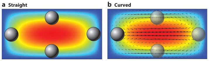
Velocity profile surface plot (red, high velocity; blue, zero velocity) (a) in a straight channel with the equilibrium positions highlighted and (b) in a slightly curved channel with vectors representing the Dean flow caused by the curvature of the channel. The opaque particles show the stable equilibrium positions, and the transparent particles are indicative of the stable positions in a straight channel made unstable under the correct conditions in a curved channel. Axial flow is into the page.
Here, we will use the terms Dean flow and secondary flow interchangeably; however, there are other secondary flows, all of which look very similar to classical Dean flow. Both alternating curves and spirals have been investigated for the generation of Dean flow in conjunction with inertial focusing of particles (3, 36). Under sufficient Dean flow, the equilibrium positions found at the center of the top and bottom surfaces of a straight rectangular channel cross section become unstable, as does the position at the outer wall owing to the impingement of the secondary flow on particles. This can leave a single lateral equilibrium position at the inside wall of the curve, as seen in Figure 2b.
All inertial focusing devices can be classified using these three nondimensional parameters and their associated force balances. We hope that the reader now has an understanding of both how the field of inertial focusing originated and its key parameters. We next describe the key forces in greater detail, taking into consideration how these forces vary in the various microfluidic architectures utilized for inertial focusing.
ESSENTIAL FORCES
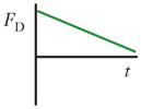
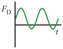
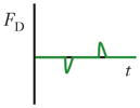
There are three forces that must be considered in inertial focusing flows: a wall interaction force, a shear gradient lift force, and a secondary-flow drag force, each depicted in Figure 3. In some channel geometries, as shown in Table 1, these forces can be ignored and sometimes can vary with position along a channel (time variation with respect to the particle). In many cases, these forces vary in three dimensions even within steady flow in a straight channel, but the force balance that determines the inertial focusing behavior remains the same.
Figure 3.

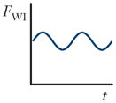
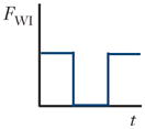
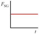
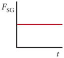
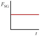
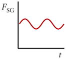
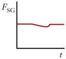
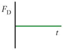
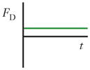
Schematics and equations describing the dominant forces in inertial focusing systems. (a) Wall interaction force: A particle moving near a wall will cause a pressure buildup on the wall side of the particle owing to the constricted flow on that side that imparts a force directed away from the wall. (b) Shear gradient lift force: A particle in a parabolic velocity field will experience a larger relative velocity on the side of the particle away from the inflection point (maximum of the parabola). This difference in velocity causes a pressure difference that imparts a force directed toward the higher-relative-velocity side of the particle. (c) Secondary-flow drag force: A particle in a uniform flow at low Reynolds number experiences a force relative to the difference between the particle velocity and the fluid velocity, also known as Stokes’ drag. Abbreviations: μ, fluid viscosity; ρ, fluid density; a, particle diameter; CSG, lift coefficient for the shear gradient lift force; CWI, lift coefficient for the wall interaction force; Dh, hydraulic diameter of the channel; FD, secondary-flow drag force; FSG, shear gradient lift force; FWI, wall interaction force; UMax, maximum velocity of the fluid; USF, secondary-flow velocity.
Table 1.
Channel geometries and force variation
| Straight |
Curved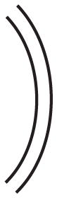
|
Spiral
|
Asymmetric curves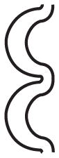
|
Contraction/expansion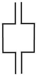
|
|
|---|---|---|---|---|---|
| Wall interaction force (FWI) |
|
|
|
|
|
| Shear gradient lift force (FSG) |
|
|
|
|
|
| Secondary-flow drag force (FD) |
|
|
|
|
|
| Equilibrium positions | 2–4 | 1–4 | 1–4 | 1–4 | 1–4 |
| Theoretical separation scaling | >a | a2 | a2 | a2 | ≥a3 |
Abbreviations: a, particle diameter; t, time.
Wall Interaction Force
Unless a particle is incredibly small (acts like a fluid molecule) or the walls are incredibly far away from the particle (unbounded flow), a particle flowing through a pipe or channel will interact with the walls of the channel. This interaction tends to cause two effects: (a) The particle will move slightly slower than the fluid, and (b) pressure will build in the constriction between the wall and the particle, causing a force directed away from the walls of a channel. This force increases inversely with the normalized distance of the particle from the wall (37). A sample streamline schematic is shown in Figure 3a. As the streamlines are diverted toward the side of the particle away from the wall, the fluid accelerates, causing low pressure on the top and higher pressure on the wall side of the particle, which generates the force (24). The equation in Figure 3a gives the scaling for the wall interaction force, where CWI is a lift coefficient that changes with Reynolds number and position (38).
Shear Gradient Lift Force
A particle in a flow will also experience a force due to the curvature of the velocity profile. A typical microfluidic velocity profile is parabolic and, thus, curved. A particle at a position in such a flow will experience velocities of different magnitudes on either side, as shown in Figure 3b, in which the velocities are relative to the velocity of the particle. The fluid flow around the particle must compensate for this difference and induces a force on the particle directed toward the side of the particle with a higher relative velocity (normally toward the walls of a microfluidic channel or areas of increasing shear). Although it may seem counterintuitive, the particle moves toward regions where the difference in velocity on either side of the particle is minimized. An important note is that this definition of the shear gradient lift force is independent of the rotation of the particle (24, 28, 38) but highly dependent on the Reynolds number and position, which are part of the lift coefficient CSG in the equation in Figure 3b (38).
The Reynolds-number dependence of the combination of shear gradient lift and wall interaction forces has been investigated both numerically (39) and empirically (30, 38, 40, 41). Although the inertial forces increase in magnitude as Reynolds number increases, the lift coefficient drops (αReC−0.5). By investigating the dynamics of the migration of particles to the centers of the faces of different-aspect-ratio rectangular channels, Zhou & Papautsky (30) also determined a second, separate lift coefficient dependent upon the rotation of the particles. Their findings are reiterated in Figure 4a, which shows the values the authors discovered for both lift coefficients using channels with different aspect ratios. A dependence of the motion toward the walls of a2 and across the walls to the center of each face of a1 allows for the separation of particles by size through first focusing the particles in a channel with one aspect ratio and then changing the width, thereby altering the force field in a manner that allows the larger particles to migrate to the new equilibrium position faster than smaller particles (42).
Figure 4.

Results from highlighted empirical studies. (a) The negative (shear gradient lift and wall interaction forces) lift coefficient and positive (slower motion to the center of rectangular faces) lift coefficient. (Panel reproduced from 30 with permission from The Royal Society of Chemistry.) (b) Sample results from a study of focusing in curved channels, decoupling Reynolds and Dean numbers. Plots show the equilibrium behavior at each flow condition for particles of different diameter (red, 15 μm; green, 9.9 μm; blue, 4.4 μm). δ = (Dh/(2ReC))1/2 and is the Reynolds number–independent part of the Dean number (59). (c) Vortex formation in an expansion/ contraction device as well as the high-ReC behaviors of trapping large (10-μm) particles while allowing smaller (5-μm) particles to pass. (Panel reprinted with permission from 66. Copyright 2011, AIP Publishing LLC.) Abbreviations: a, particle diameter; FSG, shear gradient lift force; FWI, wall interaction force; FΩ, rotation-induced lift force; ReC, channel Reynolds number; UP, particle velocity.
Higher Reynolds numbers (>100) have proven even more complex and are an active area of investigation. Whereas theoretical results have shown the equilibrium position moving toward the walls of a channel at increasing ReC (39, 43, 44), a recent paper has shown that particles may move back toward the center above a given Reynolds number (ReC ~ 300) (45). This result deserves more in-depth investigation.
Secondary-Flow Drag Force
As described above, secondary flows are useful for controlling and limiting the number of equilibrium positions within a given channel cross section. These secondary flows impart a drag force on the particles scaling linearly with the particle size and the velocity of the secondary flow. In traditional Dean flow, the secondary-flow velocities scale inversely with the radius of curvature of the channel and increase with ReC1.8–2 (36, 46–57). The additional force imparted by this flow is normally assumed to follow the Stokes’ drag relationship defined in Figure 3c, where the fluid is moving past the particle at a speed USF and imparting a drag force FD. This assumption is usually made when ReP < 1 (ReP is the Reynolds number for the particle), but it also applies in most inertial focusing flows because the secondary-flow velocities are only a fraction of the axial flow, which was used to define the particle Reynolds number in Equation 2.
Although the dynamics of inertial focusing have been proven to depend significantly on size, the eventual equilibria in a straight channel are usually colocated or in very close proximity. Dean flow offers an opportunity to provide separation based upon size owing to (a) the dependence of the drag force on particle diameter a and (b) the balance of this drag force with the shear gradient lift that scales with a3 (38). This type of separation is possible on the side of the channel cross section closer to the center of curvature where the Dean flow and lift are opposing forces. This type of separation therefore scales with ~a2 and is the one of the most utilized applications of inertial focusing to date (53, 54, 58). Another interesting application of this size dependence of Dean flow in conjunction with inertial forces is that it can separate particles that do not focus from those that are large enough to experience a significant inertial effect. This type of separation has been entitled Dean flow fractionation (46).
Experimental systems that utilize asymmetrical curves as well as spiral systems are all cases in which the forces change as the geometry changes along the length of the channel. Time-varying curvature can allow for the optimal Dean flow depending on the particle distribution. Although Dean flow enables focusing across much wider curved channels, as compared with straight channels, it actually can be detrimental in terms of the final focused streak quality (51). These varying geometry systems are quite complex but can be simplified by using a bulk shear rate. A ratio of forces value was proposed as shown in Equation 7 (3, 36, 58), and later a value of approximately 0.04 was found to be the limit above which focusing is possible (47):
| (7) |
where Rf is the ratio of shear gradient lift force, FSG, and Dean drag force, FD. Updated versions of this force balance have been presented using more accurate Dean flow velocity approximations, but they are conceptually equivalent (51, 58). It should be noted that the inertial focusing behaviors in curved channels are too complex to be predicted by a single simple value. Although a ratio of forces value of 0.04 from Equation 7 works as a guideline for achieving focusing, it does not incorporate the transient nature of the secondary flows or the cross-sectional variation of the forces that are necessary for the complete prediction of equilibrium positions.
More recently, the range of focusing behaviors within these complex secondary flows in spirals and nearly constant curvature channels has been characterized (48, 51, 56, 57). In general, the behavior of particles’ equilibrium positions have been shown to move toward the center of curvature and then away at higher flow rates. Martel & Toner (59) decoupled the effects of Reynolds and Dean numbers in such systems and presented results indicating that a more complex scaling than a simple ratio of forces is required to explain the range of inertial focusing behaviors. Some of these results are shown in Figure 4b, and they can be used to interpolate the values of curvature and ReC required for single-point focusing based on the size of the particle being focused. These results imply that the range of behaviors seen in curved and spiral inertial focusing devices necessitates that the equilibrium position moves in three dimensions. The working theory is that the redistribution of the velocity profile, a consequence of Dean flow, causes a vertical shift of the equilibrium position, which moves away from the center of curvature as the particle experiences Dean flow in that direction (33, 34, 59). This three-dimensional (3D) motion has been studied in cylindrical curved channels (55) as well as in spiral geometry (48) and is still an area of active research.
CHANNEL LENGTH
The channel length required to achieve equilibrium positions in inertial focusing is based upon the magnitudes of the above-described forces and how they vary along a particular channel. An extremely important design parameter, this length must be estimated properly. For a straight channel, Di Carlo (60) estimated this length, Lf, based on lateral migration velocity, which was calculated using the balance of shear gradient lift force and an opposing Stokes’ drag force:
| (8) |
A version of Equation 8 taking into account the two separate lift coefficients for focusing across both the axes of a rectangular cross-sectional channel is available elsewhere (30). The adjustment for curved channels is less clear owing to the complex variation in behavior, but in general the length required is shorter, so a channel length estimated using the straight channel approximation above should be sufficient. For more complicated force variations, especially along the channel, it is necessary to make further adjustments to estimate the channel length, but in general these estimates should also be similar to the straight channel result.
We hope the force balances described will be helpful in the design of inertial focusing devices, but they do not do justice to the complexity of the variation of these forces and the associated dynamics, which have been studied extensively. Although these balances give an indication of which devices will work, they will not be able to predict the actual location of the equilibrium positions or the amount of separation without a greater understanding of the 3D variation of the forces. Numerous empirical studies, which have each presented new manners of using inertial focusing or introduced new intriguing aspects of the phenomenon, deserve mention and are outlined below.
CROSS-SECTIONAL SHAPE
Two main cross-sectional shapes—rectangular and circular—have been studied in inertial focusing devices, although more recently trapezoidal cross-sectional channels have been created (61). The balance of shear gradient lift and wall interaction forces causes an annulus of equilibrium positions in a cylindrical pipe and four equilibrium positions, one centered upon each face of the cross section, in a rectilinear channel. In rectangular cross-sectional channels, the relative strengths of the four equilibrium positions vary with particle size and Reynolds number. The most important variation to note for different cross sections is that the inertial forces across a longer dimension are weaker and, thus, the dynamics of focusing will occur first across the shorter dimensions (45, 51, 62). This diminishing lateral force, due to the blunting of the velocity profile (less curved), is one of the reasons secondary flows have been used. Conveniently, the secondary flows are normally dominant in the areas of weak lateral inertial forces, thus improving the ability to focus particles across larger dimensions to more stable equilibrium positions (51). Trapezoidal channels have been studied only in terms of curved channels but have shown the ability to significantly increase the separation distance between the equilibrium positions of particles of different sizes. This enhancement derives from the trapezoidal cross section’s influence on the Dean flow in such a channel. Essentially, the change in height from low (toward the center of curvature) to high (away from the center of curvature) gives rise to a gradient in Dean flow velocities across the width of the channel. This causes a sharp transition, dependent on particle size, in the equilibrium position of a particle as the flow rate is increased (48). In curved channels, this shape allows for a different Dean flow field, essentially a gradient in drag force across the channel, which improves size-based separation (48, 61, 63).
CROSS-SECTIONAL VARIATION WITH DISTANCE ALONG CHANNEL (TIME VARYING)
One type of channel in which the cross section varies along the channel length is commonly referred to as an expansion/contraction device. In such devices, the alternation of the presence and absence of the wall interaction force was investigated to isolate the shear gradient force as the sole effect in the expanded sections of the channel. This behavior results from vortices that form in the expanded side sections, as shown in Figure 4c (64–66). Despite larger particles being equilibrated farther from the wall, the disappearance of the wall interaction force allows for much greater migration distances compared with those of smaller particles, enabling separation (65, 67, 68). In some device designs, this interaction can actually trap the larger particles within the expanded-section vortices (69). Essentially, when inertially focused particles enter a section of channel where the sidewalls are moved away sharply, at sufficient Reynolds number and depending on the size of the side chambers, separation of the flow will occur, causing vortices to form in the side chambers. When this happens, the velocity gradient in the center stream of the channel barely changes, allowing the shear gradient lift force to act on particles in the absence of the wall interaction force. Based on the initial focused positions of the particles and the strength of the shear gradient lift, larger particles migrate into the vortex regions and become trapped, whereas smaller particles do not migrate as far owing to the size scaling of the shear gradient lift force (~a3). These smaller particles stay trapped until the flow rate is decreased to a point at which the vortices are no longer stable.
Prior to flow separation and less so after flow separation, secondary flows are witnessed in the regions where the cross section expands or contracts. The secondary flows in these geometries will adjust the equilibrium positions in a manner similar to what occurs in curved channels; however, the flow and, thus, the equilibrium positions will vary along the device. The focusing of particles using expansion/contraction-generated secondary flows is normally accomplished in an asymmetric manner (expanding and contracting on one side of the channel) that has been shown to produce a single equilibrium position in different geometries (67, 70, 71).
OTHER EFFECTS
Particle Properties: Density, Shape, and Deformability
Although particle density can be assumed to be equal to that of the fluid for many cell-based applications, industrial applications and water filtration may involve particles with significantly greater density than the fluid. In such systems, the centrifugal force on the particles in curved channels must also be taken into account (54, 72, 73).
Inertial focusing is also dependent on other particle properties such as shape and deformability. The shape of a particle has a minimal effect on particle migration, although the equilibrium position of a particle is proportional to its largest effective diameter (74). Nonspherical particles rotate at frequencies that depend on their largest diameters (74, 75). Nonrigid or deformable particles have also been investigated because cells are deformable objects. Initial testing with viscous droplets in microfluidics found that the equilibrium position generally moved farther away from the walls of a channel with decreasing internal viscosity (76), which matches previous theoretical results (77–79). In general, increasing size, aspect ratio, or deformability causes the equilibrium position to shift away from the walls of a channel, as highlighted in Figure 5.
Figure 5.

Summarized effects of particle size, shape, and deformability on inertial focusing equilibrium behaviors. (a) Images of particles of different sizes equilibrating at different distances from a wall, with plots of these positions and associated rotation rates of spherical particles (38). (b, left) Photolithographic images of particles of different shapes focusing in a straight channel. (Reprinted with permission from Reference 74. Copyright 2011, AIP Publishing LLC.) (right) Oblong particles—made by melting and stretching spherical particles—focusing in a straight channel (75). (c) Droplets of different ratios of internal to surrounding fluid viscosity demonstrating the effect of deformability on inertial focusing in a straight channel. (Panel reproduced from 76 with permission from The Royal Society of Chemistry.) Abbreviations: FSG, shear gradient lift force; FWI, wall interaction force; ω, angular velocity; UP, particle velocity.
Rotation
Another intriguing aspect of inertial focusing systems is the high rotation rates of inertially focused particles. Despite being shown theoretically not to have a significant effect on the overall migration of particles, the rotation rates in a microfluidic system have been measured to be in the kilohertz range (38). This rotation changed with increasing particle aspect ratio for nonspherical particles, which followed Jeffery orbits with a period proportional to the particle aspect ratio (75). Furthermore, this rotation induced a secondary flow found to cause mixing across the channel that increased as the particle fraction was increased in the channel (80).
Interparticle Spacing
One of the most difficult to study but perhaps most intriguing effects of inertial focusing is that not only do particles migrate to equilibrium positions within a cross section, but they also become ordered or evenly spaced in the flow direction as well (3). This behavior is a result of the hydrodynamic interaction between particles. Although in many cases these effects are ignored (dilute samples), they are important in many real-world biological samples and can be dominant forces over short distances (~four particle diameters). These forces have been implicated as a cause of the loss of focusing in diverging channels and have shown intriguing properties, such as the ability to create trains of particles with hydrodynamic coupling alone (81–83). The mechanism is discussed in detail elsewhere (81, 84).
Fluid Properties
Other investigators have begun looking at the effect of non-Newtonian fluid properties on inertial focusing behaviors (85). One property of particular interest in this area is the apparent upper limit on particle volume fraction (~1–3%), after which inertial focusing behaviors break down seemingly owing to the increase in interparticle interactions. Although it is understandable that focusing behaviors will diminish with increasing particle concentration, other more unique effects, such as changes in the equilibrium locations at higher particle fractions, have been seen. These results indicate that the equilibrium positions in a straight channel with a rectangular cross section change from being centered on the long faces of the rectangle to the short faces in whole blood (45% v/v) as compared with diluted blood (<15% v/v) (86).
Another unique set of focusing behaviors occurs with the addition of polymers to a fluid, causing a slightly viscoelastic response of the fluid. In such fluids, particles will equilibrate at the centerline of the channel under the combined effects of a viscoelasticity-induced force and inertial forces (87–89). This is a simplified means of generating a single equilibrium position within a straight channel provided that the addition of a polymer to a solution is acceptable. This concept has also recently been studied in curved channels, and researchers have demonstrated the ability to separate particles by size using the balance of Dean drag and elasto-inertial effects (90).
The effectiveness of inertial focusing systems for different biomedical applications is extremely geometry dependent and increasingly complex. In fact, the theoretical size scalings for separation given in Table 1 are rarely realized experimentally. For instance, expansion/contraction channels may have an edge for separation, but these systems rely on extremely short timescales and dynamic behaviors. Interestingly, there is one example in which particles are positioned near a wall and then separated using the wall interaction force. Although this type of separation should scale with ~a6, it is almost linear with respect to particle diameter owing to the strong dependence of the wall interaction force on distance from the wall (91). This discrepancy between theory and application highlights the need for improved understanding of the spatial variations of these forces to better predict and optimize behaviors.
APPLICATIONS
Each of the additions to our understanding of inertial focusing has led to new applications of the phenomenon to biomedical problems. New applications of inertial focusing are being continuously developed and can be categorized into four main groups with wide applicability: sheathless alignment, particle separation, volume reduction, and fluid exchange. A few technologies that have been enabled by the high-speed nature of inertial focusing will also be highlighted in this section. All of the applications of inertial focusing developed to date are summarized in Table 2.
Table 2.
Applications of inertial focusing
| Application area | Application | Channel style | Sample | ReC | De | a/Dh | References |
|---|---|---|---|---|---|---|---|
| Sheathless alignment | Flow cytometry | Straight | Dilute blood (1–5% v/v) | ~7 | NA | 0.45 | 92 |
| Curved/spiral | Neuroblastoma cells (0.05% v/v) | ~100 | ~12 | 0.08 | 93 | ||
| Asymmetric curves and straight | Particles (≤ 0.1% v/v) and dilute blood (<0.2% v/v) | ~110 | ~60 | 0.15 | 52, 95 | ||
| Separation/fractionation | Rare cell isolation | Straight | Neuroblastoma cells spiked in blood (≤1% v/v) | ~130 | NA | 0.17 | 100 |
| Breast cancer cells spiked in blood (≤10% v/v) | ~38 | NA | 0.13 | 101 | |||
| Curved/spiral | Cancer cells spiked in blood then RBC lysis (<2% v/v) | ~141 | <15 | 0.08 | 63 | ||
| Cancer cells spiked in blood (<2% v/v) | ~60 | ~6 | 0.18 | 102 | |||
| Cancer cells spiked in blood (<2% v/v) | ~76 | ~13 | 0.06 | 103 | |||
| Asymmetric curves | Cancer cells in isolated leukocytes (<0.4% v/v) | ~50 | <25 | 0.20 | 96 | ||
| Expansion/contraction | Cancer cells (0.05% v/v) | ~240 | NA | 0.26 | 66, 69 | ||
| Cancer cells spiked in blood (<2% v/v) | ~100 | NA | 0.60 | 104 | |||
| Cancer cells spiked in blood (≤20% v/v) | ~312 | NA | 0.19 | 105 | |||
| Cell separation by size | Curved/spiral | Neuroblastoma and glioma cells (<1% v/v) | ~200 | ~12 | 0.08 | 58 | |
| Dilute blood (<2% v/v) | ~46 | ~4 | 0.07 | 61 | |||
| Dilute blood (<1% v/v) | ~150 | <30 | 0.06 | 106 | |||
| Cell cycle synchronization | Straight | Saccharomyces cerevisiae (<1% v/v) | ~40 | NA | 0.14 | 75 | |
| Curved/spiral | Human mesenchymal stem cells (<0.1% v/v) | ~200 | <20 | 0.07 | 107 | ||
| Platelet separation | Asymmetric curves | Dilute blood (<1% v/v) | ~112 | <43 | 0.11 | 36 | |
| Bacteria isolation/filtration | Straight | Escherichia coli spiked in dilute blood (<1% v/v) | ~125 | NA | 0.33 | 97 | |
| Plasma extraction | Expansion/contraction | Dilute blood (<3% v/v) | ~100 | NA | 0.27 | 99 | |
| Curved/spiral | Dilute blood (<0.5% v/v) | ~150 | <30 | 0.06 | 106 | ||
| Separation by deformability | Straight | Cancer cells (0.05% v/v) | ~21 | NA | 0.27 | 76 | |
| Fluid exchange and mixing | Cell staining platform | Expansion/contraction | Cancer cells spiked in blood (<1% v/v) | ~183 | NA | 0.26 | 69 |
| Cancer cells (0.05% v/v) | ~200 | NA | 0.31 | 116 | |||
| Solution exchange | Straight | RBC lysed blood (<0.05% v/v) | ~50 | NA | 0.23 | 110 | |
| Expansion/contraction | Cancer cells spiked in blood (<1% v/v) | ~183 | NA | 0.26 | 69 | ||
| Fluid mixing | Straight | Dilute blood (1–5% v/v) | <60 | NA | 0.17 | 80 | |
| Volume reduction | Concentrating bioparticles | Curved/spiral | S. cerevisiae (<1% v/v) | ~50 | <12 | 0.05 | 56 |
| Water filtration | Curved/spiral | Particles | ~20 | <2 | 0.07 | 54 | |
| Particle classification | Curved/spiral | Particles | <600 | <40 | 0.05 | 72 | |
| Particles | <462 | <30 | 0.12 | 73 | |||
| Enabled technologies | Deformability measurements | Straight | Cancer cells (0.05% v/v) | ~21 | NA | 0.27 | 76 |
| Asymmetric curves | Cancer cells, stem cells, and leukocytes (<0.1% v/v) | ~75 | <30 | 0.24 | 108, 112 | ||
| Single cell encapsulation | Straight | Leukemic cells (HL60) | ~8 | NA | 0.34 | 50, 115 | |
| Curved/spiral | Leukemic cells (HL60 and K652) | ~8 | <1 | 0.33 | 114 | ||
| Electroporation and DNA delivery | Curved/spiral | Chinese hamster ovary cells (<0.05% v/v) | ~68 | <19 | 0.31 | 65 | |
| Expansion/contraction | Cancer cells (0.05% v/v) | ~200 | NA | 0.31 | 116 |
Abbreviations: a, particle diameter; De, Dean number (strength of the curvature-generated secondary flows); Dh, hydraulic diameter of a channel [Dh = 2hw/(h + w), where h and w are the height and width, respectively, of the microchannel]; NA, not applicable; ReC, channel Reynolds number.
Sheathless Alignment
For many biological measurements, including those made in cytometry, the precise positioning of the cells near a detector and spacing between the particles are paramount to achieving accurate and reproducible results. Current technologies utilize sheath flows that surround the sample flow in order to space cells out evenly for more accurate counting. By taking advantage of inertial focusing, new technologies can align and order particles without sheath flows and the associated reduction in sample flow rate (52, 92–95). This concept has also been utilized for the magnetic isolation of labeled and unlabeled cell populations for rare-cell detection in blood (96), as shown in Figure 6a.
Figure 6.

Highlighted applications of inertial focusing. (a) Sheathless alignment of cells in asymmetric curves for enhanced separation efficiency in magnetophoresis (96), showing cells (i) prior to focusing, (ii) after focusing, (iii) during magnetophoresis, and (iv) after complete separation. (b) Isolation of CTCs from blood cells by size in a spiral device. (Panel reprinted by permission from Macmillan Publishers Ltd: Scientific Reports from 103, copyright 2013.) (c) Bacteria filtration from blood using a straight inertial focusing channel (97). (Panel reprinted with permission; copyright 2010 Wiley Periodicals, Inc.) (d) Extraction of plasma from diluted blood in a spiral device. (Panel reprinted with permission from 106; copyright 2013, AIP Publishing LLC.) (e) Volume reduction of a sample of bioparticles using a spiral inertial focusing device. (Panel reprinted with permission from 57; copyright 2013, AIP Publishing LLC.) (f) Solution exchange in which a bead moves from one fluid to another in a straight channel of changing aspect ratio (110). (Panel reprinted with permission; copyright 2012, Wiley-VCH Verlag GmbH & Co. KGaA, Weinheim.) Abbreviations: CTC, circulating tumor cell; De, Dean number.
Particle Separation
The most utilized application of inertial focusing is separation of particles based upon a range of mechanical properties such as size, shape, and deformability. Different means of separating particles rely on one of two simple principles: (a) focus one particle and remove the rest, such as in Dean flow fractionation (46), or (b) focus all particles separately using an intrinsic hydrodynamic difference.
The first type of separation is usually accomplished between cells or targets of significantly different sizes using the difference in ReP in order to achieve separation. This concept has been used for filtering bacteria from dilute blood (97) as shown in Figure 6c, sampling blood plasma as shown in Figure 6d (98, 99), and isolating platelets (36). The second type of separation is more common and has been used for the isolation of circulating tumor cells from blood based upon some cancer cell populations being larger than all other naturally occurring blood cells (see Figure 6b) (63, 66, 96, 100–105). This type of separation has been applied more generically to other types of cellular suspensions in which a size difference is apparent, including human mesenchymal stem cells, whose size varies significantly with stage in the cell cycle (48, 58, 106, 107). Fungal cell samples (e.g., Saccharomyces cerevisiae) can also be separated based upon their shape and size, both of which depend on growth-cycle stage (75). Different cancer cell lines have been separated by their differences in deformability as well (76). In this study (76), modified breast cancer cells, known to be more metastatic, equilibrated farther from the wall than unmodified cells; in other words, the modified cells were more deformable (modMCF7 versus MCF7). Deformability is now being utilized as a mechanical biomarker for the detection of cancer, sepsis, and other diseases (108).
Volume Reduction
Although many of the separation techniques discussed above accomplish enrichment in addition to separation, it is also possible to use inertial focusing to reduce the size of a sample by focusing all of the cells and then collecting the cell-rich and cell-free streams separately in curved channels (see Figure 6e) (57, 109). This technique has been applied to water filtration as well (54, 55). Inertial focusing has shown promise for continuous concentration of cells, replacing the need for large-scale centrifugation, but faces several challenges, including but not limited to the dependence of equilibrium positions upon particle size, the breakdown of the behaviors at high volume fractions, and the difficulty of dealing with extremely low flow rates at the outlets of the devices.
Solution Exchange
A few investigators have developed new means of using inertial focusing for the transfer of cells between fluids with minimal mixing at high speeds. In a straight channel, this is accomplished by a change in the channel aspect ratio: After joining with another flow, the cells initially focused to the center of a channel will migrate into the coflowing fluid as the center of the channel changes positions (110). An example of this is shown in Figure 6f, which provides successive images of a particle migrating from one fluid into the other without mixing of the two streams. The other manner in which this is accomplished is through using expansion/contraction channels and trapping cells within the vortices formed in the expanded sections at higher ReC. This technique has been used for automated cell staining and washing by changing the fluids being pushed through the channel without altering the overall flow rates, leaving the cells trapped in the vortices and changing the fluid surrounding the cells (69).
Enabled Technologies
New technologies that increase the flow rate and speeds in microfluidics while retaining the ability to control the particle positions are available. One of these enabled applications is the ability to measure the deformability of cells at much higher rates using extensional flows. This type of measurement, depicted schematically in Figure 7a, has shown promise for detecting cancers and identifying the states of stem cells (108, 111, 112), and the realm of possibilities for this technique is still expanding. The high speed of particles in inertial focusing flows is also tailor-made for single-cell encapsulation technologies, which are reviewed elsewhere (113). By matching the frequency of cell ordering in the longitudinal direction and the production of droplets, these technologies drastically improve the encapsulation efficiency of single cells (50, 114, 115). Examples of these technologies are highlighted in Figure 7b, in which the production of droplets (>1,000 droplets per second) containing either single cells (left) or pairs of cells is imaged using a high-speed camera. Finally, using the cell-trapping concept in expansion/contraction channels, as shown in Figure 7c, enables more uniform electroporation of cells, owing to the combination of cell rotation and fluid motion, thereby notably increasing the viability of cells after the vector delivery process (116).
Figure 7.

Technologies enabled by inertial focusing behaviors. (a) Measurement of individual cell deformability characteristics for disease detection at a rate of thousands of cells per second (108). (b) Coupling of inertial ordering of cells and droplet encapsulation, which drastically improves the number of droplets created that hold a single cell and allows controlled encapsulation of particle pairs (114, 115). (c) Improved viability during electroporation by taking advantage of the spinning and vortexing of cells trapped in expansion/contraction devices. (Panel reproduced from 116 with permission from The Royal Society of Chemistry.)
SUMMARY AND OUTLOOK
Inertial focusing is an effective means of controlling particle positions at high speeds in microfluidic channels. That being said, it is also extremely complex from a theoretical perspective. Although it is feasible to design a channel and increase the flow rate until some type of focusing behavior is achieved, the ability to predict the outcomes of an experiment still eludes researchers. This is one challenge posed to future inertial focusing researchers: Can we predict and optimize the behaviors for different biomedical applications based upon first principles?
Another of the many intriguing areas for future research on inertial focusing is the ability to deal with concentrated cellular samples. Currently, it seems that most inertial focusing devices begin to have diminished performance at around 1–3% v/v. The mechanism here may be due to the non-Newtonian nature of suspensions or, perhaps, the interparticle forces that become more frequent. In either case, a more detailed understanding is required. Along similar lines, understanding the nature of particle train development, especially in a curved channel, will allow for the optimization of inertial flows for improving the aforementioned concentration limit. The theory behind these technologies is in need of simplified design principles, but as of yet the forces and their variation are too complex for simple models to encompass. We do not yet know how simple a model can be and still capture the essential components of predicting the equilibrium position locations, especially in curved channels. Finally, although the dependence of the forces on particle size is important for separation applications, it can also pose challenges to cytometry and volume reduction applications, as differently sized particles have different equilibrium positions. Tailoring the variation of the forces should allow size-independent single equilibrium position particle focusing, which would be ideal for these applications.
Inertial focusing has been incredibly successful in the years since the original application of its basic principles to microfluidics. The field not only has grown significantly in terms of the number of active researchers but also has demonstrated numerous exciting possibilities, with more opportunities on the horizon. Behind these seemingly unlimited applications in biomedical engineering are the unique physics that cause the behaviors, which are also of theoretical interest. For these reasons, it is easy to believe that inertial focusing and related enabled technologies will be a highly active field for years to come.
Footnotes
DISCLOSURE STATEMENT
The authors are not aware of any affiliations, memberships, funding, or financial holdings that might be perceived as affecting the objectivity of this review.
LITERATURE CITED
- 1.Pamme N. Continuous flow separations in microfluidic devices. Lab Chip. 2007;7:1644–59. doi: 10.1039/b712784g. [DOI] [PubMed] [Google Scholar]
- 2.Gossett DR, Weaver WM, Mach AJ, Hur SC, Tse HTK, et al. Label-free cell separation and sorting in microfluidic systems. Anal Bioanal Chem. 2010;397:3249–67. doi: 10.1007/s00216-010-3721-9. [DOI] [PMC free article] [PubMed] [Google Scholar]
- 3.Di Carlo D, Irimia D, Tompkins R, Toner M. Continuous inertial focusing, ordering, and separation of particles in microchannels. Proc Natl Acad Sci USA. 2007;104:18892–97. doi: 10.1073/pnas.0704958104. [DOI] [PMC free article] [PubMed] [Google Scholar]
- 4.Choi S, Song S, Choi C, Park JK. Hydrophoretic sorting of micrometer and submicrometer particles using anisotropic microfluidic obstacles. Anal Chem. 2008;81:50–55. doi: 10.1021/ac801720x. [DOI] [PubMed] [Google Scholar]
- 5.Loutherback K, Chou KS, Newman J, Puchalla J, Austin RH, Sturm JC. Improved performance of deterministic lateral displacement arrays with triangular posts. Microfluid Nanofluid. 2010;9:1143–49. [Google Scholar]
- 6.Huh D, Bahng J, Ling Y, Wei H, Kripfgans O, et al. A gravity-driven microfluidic particle sorting device with hydrodynamic separation amplification. Anal Chem. 2007;79:1369–76. doi: 10.1021/ac061542n. [DOI] [PMC free article] [PubMed] [Google Scholar]
- 7.Morton K, Loutherback K, Inglis D, Tsui O, Sturm J, et al. Hydrodynamic metamaterials: microfabricated arrays to steer, refract, and focus streams of biomaterials. Proc Natl Acad Sci USA. 2008;105:7434–38. doi: 10.1073/pnas.0712398105. [DOI] [PMC free article] [PubMed] [Google Scholar]
- 8.Choi S, Ku T, Song S, Choi C, Park J-K. Hydrophoretic high-throughput selection of platelets in physiological shear-stress range. Lab Chip. 2011;11:413–18. doi: 10.1039/c0lc00148a. [DOI] [PubMed] [Google Scholar]
- 9.Choi S, Song S, Choi C, Park J. Continuous blood cell separation by hydrophoretic filtration. Lab Chip. 2007;7:1532–38. doi: 10.1039/b705203k. [DOI] [PubMed] [Google Scholar]
- 10.Huang LR, Cox EC, Austin RH, Sturm JC. Continuous particle separation through deterministic lateral displacement. Science. 2004;304:987–90. doi: 10.1126/science.1094567. [DOI] [PubMed] [Google Scholar]
- 11.Inglis DW, Davis JA, Austin RH, Sturm JC. Critical particle size for fractionation by deterministic lateral displacement. Lab Chip. 2006;6:655–58. doi: 10.1039/b515371a. [DOI] [PubMed] [Google Scholar]
- 12.Kralj J, Lis M, Schmidt M, Jensen K. Continuous dielectrophoretic size-based particle sorting. Anal Chem. 2006;78:5019–25. doi: 10.1021/ac0601314. [DOI] [PubMed] [Google Scholar]
- 13.Zhu J, Tzeng T-RJ, Xuan X. Continuous dielectrophoretic separation of particles in a spiral microchannel. Electrophoresis. 2010;31:1382–88. doi: 10.1002/elps.200900736. [DOI] [PubMed] [Google Scholar]
- 14.Voldman J. Electrical forces for microscale cell manipulation. Annu Rev Biomed Eng. 2006;8:425–54. doi: 10.1146/annurev.bioeng.8.061505.095739. [DOI] [PubMed] [Google Scholar]
- 15.Petersson F, Åberg L, Swärd-Nilsson AM, Laurell T. Free flow acoustophoresis: microfluidic-based mode of particle and cell separation. Anal Chem. 2007;79:5117–23. doi: 10.1021/ac070444e. [DOI] [PubMed] [Google Scholar]
- 16.Miltenyi S, Müller W, Weichel W, Radbruch A. High gradient magnetic cell separation with MACS. Cytometry. 1990;11:231–38. doi: 10.1002/cyto.990110203. [DOI] [PubMed] [Google Scholar]
- 17.Toner M, Irimia D. Blood-on-a-chip. Annu Rev Biomed Eng. 2005;7:77–103. doi: 10.1146/annurev.bioeng.7.011205.135108. [DOI] [PMC free article] [PubMed] [Google Scholar]
- 18.Lenshof A, Laurell T. Continuous separation of cells and particles in microfluidic systems. Chem Soc Rev. 2010;39:1203–17. doi: 10.1039/b915999c. [DOI] [PubMed] [Google Scholar]
- 19.Tsutsui H, Ho C-M. Cell separation by non-inertial force fields in microfluidic systems. Mech Res Commun. 2009;36:92–103. doi: 10.1016/j.mechrescom.2008.08.006. [DOI] [PMC free article] [PubMed] [Google Scholar]
- 20.Whitesides G. The origins and the future of microfluidics. Nature. 2006;442:368–73. doi: 10.1038/nature05058. [DOI] [PubMed] [Google Scholar]
- 21.Segré G, Silberberg A. Radial particle displacements in Poiseuille flow of suspensions. Nature. 1961;189:209–10. [Google Scholar]
- 22.Rubinow S, Keller JB. The transverse force on a spinning sphere moving in a viscous fluid. J Fluid Mech. 1961;11:447–59. [Google Scholar]
- 23.Matas J, Morris J, Guazzelli É. Lateral forces on a sphere. Oil Gas Sci Technol. 2004;59:59–70. [Google Scholar]
- 24.Feng J, Hu H, Joseph D. Direct simulation of initial value problems for the motion of solid bodies in a Newtonian fluid. Part 2: Couette and Poiseuille flows. J Fluid Mech. 1994;277:271–301. [Google Scholar]
- 25.Saffman PG. The lift on a small sphere in a slow shear flow. J Fluid Mech. 1965;22:385–400. [Google Scholar]
- 26.Repetti R, Leonard E. Segré-Silberberg annulus formation: a possible explanation. Nature. 1964;203:1346–48. [Google Scholar]
- 27.Jeffrey R, Pearson J. Particle motion in laminar vertical tube flow. J Fluid Mech. 2006;22:721–35. [Google Scholar]
- 28.Ho B, Leal L. Inertial migration of rigid spheres in two-dimensional unidirectional flows. J Fluid Mech. 1974;65:365–400. [Google Scholar]
- 29.Vasseur P, Cox R. The lateral migration of a spherical particle in two-dimensional shear flows. J Fluid Mech. 1976;78:385–413. [Google Scholar]
- 30.Zhou J, Papautsky I. Fundamentals of inertial focusing in microchannels. Lab Chip. 2013;13:1121–32. doi: 10.1039/c2lc41248a. [DOI] [PubMed] [Google Scholar]
- 31.Dean WR. Fluid motion in a curved channel. Proc R Soc A Math Phys Eng Sci. 1928;121:402–20. [Google Scholar]
- 32.Berger S, Talbot L, Yao L. Flow in curved pipes. Annu Rev Fluid Mech. 1983;15:461–512. [Google Scholar]
- 33.Vriend HJD. Velocity redistribution in curved rectangular channels. J Fluid Mech. 1981;107:423–39. [Google Scholar]
- 34.Norouzi M, Biglari N. An analytical solution for Dean flow in curved ducts with rectangular cross section. Phys Fluids. 2013;25:053602. [Google Scholar]
- 35.Cheng K, Akiyama M. Laminar forced convection heat transfer in curved rectangular channels. Int J Heat Mass Transf. 1970;13:471–90. [Google Scholar]
- 36.Di Carlo D, Edd J, Irimia D, Tompkins R, Toner M. Equilibrium separation and filtration of particles using differential inertial focusing. Anal Chem. 2008;80:2204–11. doi: 10.1021/ac702283m. [DOI] [PubMed] [Google Scholar]
- 37.Zeng L, Najjar F, Balachandar S, Fischer P. Forces on a finite-sized particle located close to a wall in a linear shear flow. Phys Fluids. 2009;21:033302. [Google Scholar]
- 38.Di Carlo D, Edd J, Humphry K, Stone H, Toner M. Particle segregation and dynamics in confined flows. Phys Rev Lett. 2009;102:094503. doi: 10.1103/PhysRevLett.102.094503. [DOI] [PMC free article] [PubMed] [Google Scholar]
- 39.Asmolov E. The inertial lift on a spherical particle in a plane Poiseuille flow at large channel Reynolds number. J Fluid Mech. 1999;381:63–87. [Google Scholar]
- 40.Choi Y-S, Seo K-W, Lee S-J. Lateral and cross-lateral focusing of spherical particles in a square microchannel. Lab Chip. 2011;11:460–65. doi: 10.1039/c0lc00212g. [DOI] [PubMed] [Google Scholar]
- 41.Choi Y-S, Lee S-J. Holographic analysis of three-dimensional inertial migration of spherical particles in micro-scale pipe flow. Microfluid Nanofluid. 2010;9:819–29. [Google Scholar]
- 42.Zhou J, Giridhar PV, Kasper S, Papautsky I. Modulation of aspect ratio for complete separation in an inertial microfluidic channel. Lab Chip. 2013;13:1919–29. doi: 10.1039/c3lc50101a. [DOI] [PubMed] [Google Scholar]
- 43.Matas J-P, Morris JF, Guazzelli É. Inertial migration of rigid spherical particles in Poiseuille flow. J Fluid Mech. 2004;515:171–95. [Google Scholar]
- 44.Matas J-P, Morris J, Guazzelli É. Lateral force on a rigid sphere in large-inertia laminar pipe flow. J Fluid Mech. 2009;621:59–67. [Google Scholar]
- 45.Ciftlik A, Ettori M, Gijs M. High throughput-per-footprint inertial focusing. Small. 2013;9:2764–73. doi: 10.1002/smll.201201770. [DOI] [PubMed] [Google Scholar]
- 46.Bhagat A, Kuntaegowdanahalli S, Papautsky I. Continuous particle separation in spiral microchannels using Dean flows and differential migration. Lab Chip. 2008;8:1906–14. doi: 10.1039/b807107a. [DOI] [PubMed] [Google Scholar]
- 47.Gossett DR, Carlo DD. Particle focusing mechanisms in curving confined flows. Anal Chem. 2009;81:8459–65. doi: 10.1021/ac901306y. [DOI] [PubMed] [Google Scholar]
- 48.Guan G, Wu L, Bhagat AA, Li Z, Chen PCY, et al. Spiral microchannel with rectangular and trapezoidal cross-sections for size based particle separation. Sci Rep. 2013;3:1495. doi: 10.1038/srep01475. [DOI] [PMC free article] [PubMed] [Google Scholar]
- 49.Hasni A, Göbbels K, Thiebes A, Bräunig P, Mokwa W, Schnakenberg U. Focusing and sorting of particles in spiral microfluidic channels. Procedia Eng. 2011;25:1197–200. [Google Scholar]
- 50.Kemna E, Schoeman R, Wolbers F, Vermes I, Weitz DA, Van Den Berg A. High-yield cell ordering and deterministic cell-in-droplet encapsulation using Dean flow in a curved microchannel. Lab Chip. 2012;12:2881–87. doi: 10.1039/c2lc00013j. [DOI] [PubMed] [Google Scholar]
- 51.Martel J, Toner M. Inertial focusing dynamics in spiral microchannels. Phys Fluids. 2012;24:032001. doi: 10.1063/1.3681228. [DOI] [PMC free article] [PubMed] [Google Scholar]
- 52.Oakey J, Applegate R, Jr, Arellano E, Di Carlo D. Particle focusing in staged inertial microfluidic devices for flow cytometry. Anal Chem. 2010;82:3862–67. doi: 10.1021/ac100387b. [DOI] [PMC free article] [PubMed] [Google Scholar]
- 53.Russom A, Gupta A, Nagrath S, Carlo D, Edd J, Toner M. Differential inertial focusing of particles in curved low-aspect-ratio microchannels. New J Phys. 2009;11:075025. doi: 10.1088/1367-2630/11/7/075025. [DOI] [PMC free article] [PubMed] [Google Scholar]
- 54.Seo J, Lean M, Kole A. Membrane-free microfiltration by asymmetric inertial migration. Appl Phys Lett. 2007;91:033901. [Google Scholar]
- 55.Seo KW, Choi YS, Lee SJ. Dean-coupled inertial migration and transient focusing of particles in a curved microscale pipe flow. Exp Fluids. 2012;53:1867–77. [Google Scholar]
- 56.Xiang N, Chen K, Sun D, Wang S, Yi H, Ni Z. Quantitative characterization of the focusing process and dynamic behavior of differently sized microparticles in a spiral microchannel. Microfluid Nanofluid. 2012;14:89–99. [Google Scholar]
- 57.Xiang N, Yi H, Chen K, Sun D, Jiang D, et al. High-throughput inertial particle focusing in a curved microchannel: insights into the flow-rate regulation mechanism and process model. Biomicrofluidics. 2013;7:044116. doi: 10.1063/1.4818445. [DOI] [PMC free article] [PubMed] [Google Scholar]
- 58.Kuntaegowdanahalli SS, Bhagat AAS, Kumar G, Papautsky I. Inertial microfluidics for continuous particle separation in spiral microchannels. Lab Chip. 2009;9:2973–80. doi: 10.1039/b908271a. [DOI] [PubMed] [Google Scholar]
- 59.Martel JM, Toner M. Particle focusing in curved microfluidic channels. Sci Rep. 2013;3:3340. [Google Scholar]
- 60.Di Carlo D. Inertial microfluidics. Lab Chip. 2009;9:3038–46. doi: 10.1039/b912547g. [DOI] [PubMed] [Google Scholar]
- 61.Wu L, Guan G, Hou H, Bhagat A, Han J. Separation of leukocytes from blood using spiral channel with trapezoid cross-section. Anal Chem. 2012;84:9324–31. doi: 10.1021/ac302085y. [DOI] [PubMed] [Google Scholar]
- 62.Bhagat A, Kuntaegowdanahalli S, Papautsky I. Enhanced particle filtration in straight microchannels using shear-modulated inertial migration. Phys Fluids. 2008;20:101702. [Google Scholar]
- 63.Majid EW, Guan G, Khoo BL, Lee WC, Bhagat AAS, et al. Slanted spiral microfluidics for the ultra-fast, label-free isolation of circulating tumor cells. Lab Chip. 2013;14:128–37. doi: 10.1039/c3lc50617g. [DOI] [PubMed] [Google Scholar]
- 64.Park J, Song S, Jung H. Continuous focusing of microparticles using inertial lift force and vorticity via multiorifice microfluidic channels. Lab Chip. 2009;9:939–48. doi: 10.1039/b813952k. [DOI] [PubMed] [Google Scholar]
- 65.Wang X, Zhou J, Papautsky I. Vortex-aided inertial microfluidic device for continuous particle separation with high size-selectivity, efficiency, and purity. Biomicrofluidics. 2013;7:044119. doi: 10.1063/1.4818906. [DOI] [PMC free article] [PubMed] [Google Scholar]
- 66.Hur SC, Mach AJ, Di Carlo D. High-throughput size-based rare cell enrichment using microscale vortices. Biomicrofluidics. 2011;5:022206. doi: 10.1063/1.3576780. [DOI] [PMC free article] [PubMed] [Google Scholar]
- 67.Zhang J, Li M, Li W, Alici G. Inertial focusing in a straight channel with asymmetrical expansion–contraction cavity arrays using two secondary flows. J Micromech Microeng. 2013;23:085023. [Google Scholar]
- 68.Park JS, Jung HI. Multiorifice flow fractionation: continuous size-based separation of microspheres using a series of contraction/expansion microchannels. Anal Chem. 2009;81:8280–88. doi: 10.1021/ac9005765. [DOI] [PubMed] [Google Scholar]
- 69.Mach AJ, Kim JH, Arshi A, Hur SC, Di Carlo D. Automated cellular sample preparation using a Centrifuge-on-a-Chip. Lab Chip. 2011;11:2827–34. doi: 10.1039/c1lc20330d. [DOI] [PubMed] [Google Scholar]
- 70.Chung A, Pulido D, Oka JC, Amini H, Masaeli M, Di Carlo D. Microstructure-induced helical vortices allow single-stream and long-term inertial focusing. Lab Chip. 2013;13:2942–49. doi: 10.1039/c3lc41227j. [DOI] [PubMed] [Google Scholar]
- 71.Chung AJ, Gossett DR, Di Carlo D. Three dimensional, sheathless, and high-throughput microparticle inertial focusing through geometry-induced secondary flows. Small. 2012;9:685–90. doi: 10.1002/smll.201202413. [DOI] [PubMed] [Google Scholar]
- 72.Ookawara S, Higashi R, Street D, Ogawa K. Feasibility study on concentration of slurry and classification of contained particles by microchannel. Chem Eng J. 2004;101:171–78. [Google Scholar]
- 73.Ookawara S, Oozeki N, Ogawa K, Löb P, Hessel V. Process intensification of particle separation by lift force in arc microchannel with bifurcation. Chem Eng Proc Process Intensif. 2010;49:696–702. [Google Scholar]
- 74.Hur SC, Choi SE, Kwon S, Di Carlo D. Inertial focusing of non-spherical microparticles. Appl Phys Lett. 2011;99:044101. [Google Scholar]
- 75.Masaeli M, Sollier E, Amini H, Mao W, Camacho K, et al. Continuous inertial focusing and separation of particles by shape. Phys Rev X. 2012;2:031017. [Google Scholar]
- 76.Hur SC, Henderson-MacLennan NK, McCabe ERB, Di Carlo D. Deformability-based cell classification and enrichment using inertial microfluidics. Lab Chip. 2011;11:912–20. doi: 10.1039/c0lc00595a. [DOI] [PubMed] [Google Scholar]
- 77.Takemura F, Takagi S, Magnaudet J, Matsumoto Y. Drag and lift forces on a bubble rising near a vertical wall in a viscous liquid. J Fluid Mech. 2002;461:277–300. [Google Scholar]
- 78.Takemura F, Magnaudet J. The transverse force on clean and contaminated bubbles rising near a vertical wall at moderate Reynolds number. J Fluid Mech. 2003;495:235–53. [Google Scholar]
- 79.Leal L. Particle motions in a viscous fluid. Annu Rev Fluid Mech. 1980;12:435–76. [Google Scholar]
- 80.Amini H, Sollier E, Weaver WM, Di Carlo D. Intrinsic particle-induced lateral transport in microchannels. Proc Natl Acad Sci USA. 2012;109:11593–98. doi: 10.1073/pnas.1207550109. [DOI] [PMC free article] [PubMed] [Google Scholar]
- 81.Lee W, Amini H, Stone HA, Di Carlo D. Dynamic self-assembly and control of microfluidic particle crystals. Proc Natl Acad Sci USA. 2010;107:22413–18. doi: 10.1073/pnas.1010297107. [DOI] [PMC free article] [PubMed] [Google Scholar]
- 82.Humphry KJ. PhD Thesis. Harvard Univ; Cambridge, MA: 2009. Low Reynolds number flows for microfluidic technologies: instabilities, drops, and inertially ordered particles. [Google Scholar]
- 83.Humphry KJ, Kulkarni PM, Weitz DA, Morris JF, Stone HA. Axial and lateral particle ordering in finite Reynolds number channel flows. Phys Fluids. 2010;22:081703. [Google Scholar]
- 84.Matas J, Glezer V, Guazzelli É, Morris J. Trains of particles in finite-Reynolds-number pipe flow. Phys Fluids. 2004;16:4192–95. [Google Scholar]
- 85.Huang P, Joseph D. Effects of shear thinning on migration of neutrally buoyant particles in pressure driven flow of Newtonian and viscoelastic fluids. J Non-Newtonian Fluid Mech. 2000;90:159–85. [Google Scholar]
- 86.Lim EJ, Ober TJ, Edd JF, McKinley GH, Toner M. Visualization of microscale particle focusing in diluted and whole blood using particle trajectory analysis. Lab Chip. 2012;12:2199–210. doi: 10.1039/c2lc21100a. [DOI] [PMC free article] [PubMed] [Google Scholar]
- 87.Nam J, Lim H, Kim D, Jung H, Shin S. Continuous separation of microparticles in a microfluidic channel via the elasto-inertial effect of non-Newtonian fluid. Lab Chip. 2012;12:1347–54. doi: 10.1039/c2lc21304d. [DOI] [PubMed] [Google Scholar]
- 88.Yang S, Kim J, Lee S, Lee S, Kim J. Sheathless elasto-inertial particle focusing and continuous separation in a straight rectangular microchannel. Lab Chip. 2010;11:266–73. doi: 10.1039/c0lc00102c. [DOI] [PubMed] [Google Scholar]
- 89.Kang K, Lee SS, Hyun K, Lee SJ, Kim JM. DNA-based highly tunable particle focuser. Nat Commun. 2013;4:2567. doi: 10.1038/ncomms3567. [DOI] [PubMed] [Google Scholar]
- 90.Lee DJ, Brenner H, Youn JR, Song YS. Multiplex particle focusing via hydrodynamic force in viscoelastic fluids. Sci Rep. 2013;3:3258. doi: 10.1038/srep03258. [DOI] [PMC free article] [PubMed] [Google Scholar]
- 91.Wu Z, Willing B, Bjerketorp J, Jansson JK, Hjort K. Soft inertial microfluidics for high throughput separation of bacteria from human blood cells. Lab Chip. 2009;9:1193–99. doi: 10.1039/b817611f. [DOI] [PubMed] [Google Scholar]
- 92.Hur SC, Tse HTK, Di Carlo D. Sheathless inertial cell ordering for extreme throughput flow cytometry. Lab Chip. 2010;10:274–80. doi: 10.1039/b919495a. [DOI] [PubMed] [Google Scholar]
- 93.Bhagat AAS, Kuntaegowdanahalli SS, Kaval N, Seliskar CJ, Papautsky I. Inertial microfluidics for sheath-less high-throughput flow cytometry. Biomed Microdevices. 2010;12:187–95. doi: 10.1007/s10544-009-9374-9. [DOI] [PubMed] [Google Scholar]
- 94.Mao X, Lin S-C, Dong C, Huang T. Single-layer planar on-chip flow cytometer using microfluidic drifting based three-dimensional (3D) hydrodynamic focusing. Lab Chip. 2009;9:1583–89. doi: 10.1039/b820138b. [DOI] [PubMed] [Google Scholar]
- 95.Kotz KT, Petrofsky AC, Haghgooie R, Granier R, Toner M, Tompkins RG. Inertial focusing cytometer with integrated optics for particle characterization. Technology. 2013;1:27–36. doi: 10.1142/S233954781350009X. [DOI] [PMC free article] [PubMed] [Google Scholar]
- 96.Ozkumur E, Shah AM, Ciciliano JC, Emmink BL, Miyamoto DT, et al. Inertial focusing for tumor antigen–dependent and –independent sorting of rare circulating tumor cells. Sci Transl Med. 2013;5:179ra47. doi: 10.1126/scitranslmed.3005616. [DOI] [PMC free article] [PubMed] [Google Scholar]
- 97.Mach AJ, Di Carlo D. Continuous scalable blood filtration device using inertial microfluidics. Biotechnol Bioeng. 2010;107:302–11. doi: 10.1002/bit.22833. [DOI] [PubMed] [Google Scholar]
- 98.Kersaudy-Kerhoas M, Dhariwal R, Desmulliez MPY, Jouvet L. Hydrodynamic blood plasma separation in microfluidic channels. Microfluid Nanofluid. 2010;8:105–14. [Google Scholar]
- 99.Faivre M, Abkarian M, Bickraj K, Stone HA. Geometrical focusing of cells in a microfluidic device: an approach to separate blood plasma. Biorheology. 2006;43:147–59. [PubMed] [Google Scholar]
- 100.Tanaka T, Ishikawa T, Numayama-Tsuruta K, Imai Y, Ueno H, et al. Separation of cancer cells from a red blood cell suspension using inertial force. Lab Chip. 2012;12:4336–43. doi: 10.1039/c2lc40354d. [DOI] [PubMed] [Google Scholar]
- 101.Tanaka T, Ishikawa T, Numayama-Tsuruta K, Imai Y, Ueno H, et al. Inertial migration of cancer cells in blood flow in microchannels. Biomed Microdevices. 2011;14:25–33. doi: 10.1007/s10544-011-9582-y. [DOI] [PubMed] [Google Scholar]
- 102.Sun J, Li M, Liu C, Zhang Y, Liu D, et al. Double spiral microchannel for label-free tumor cell separation and enrichment. Lab Chip. 2012;12:3952–60. doi: 10.1039/c2lc40679a. [DOI] [PubMed] [Google Scholar]
- 103.Hou HW, Warkiani ME, Khoo BL, Li ZR, Soo RA, et al. Isolation and retrieval of circulating tumor cells using centrifugal forces. Sci Rep. 2013;3:1259. doi: 10.1038/srep01259. [DOI] [PMC free article] [PubMed] [Google Scholar]
- 104.Bhagat A, Hou H, Li L, Lim C, Han J. Pinched flow coupled shear-modulated inertial microfluidics for high-throughput rare blood cell separation. Lab Chip. 2011;11:1870–78. doi: 10.1039/c0lc00633e. [DOI] [PubMed] [Google Scholar]
- 105.Sollier E, Go DE, Che J, Gossett DR, O’Byrne S, et al. Size-selective collection of circulating tumor cells using Vortex technology. Lab Chip. 2014;14:63–77. doi: 10.1039/c3lc50689d. [DOI] [PubMed] [Google Scholar]
- 106.Nivedita N, Papautsky I. Continuous separation of blood cells in spiral microfluidic devices. Biomicrofluidics. 2013;7:054101. doi: 10.1063/1.4819275. [DOI] [PMC free article] [PubMed] [Google Scholar]
- 107.Lee WC, Bhagat AAS, Huang S, Van Vliet KJ, Han J, Lim CT. High-throughput cell cycle synchronization using inertial forces in spiral microchannels. Lab Chip. 2011;11:1359–67. doi: 10.1039/c0lc00579g. [DOI] [PubMed] [Google Scholar]
- 108.Gossett DR, Tse HTK, Lee SA, Ying Y, Lindgren AG, et al. Hydrodynamic stretching of single cells for large population mechanical phenotyping. Proc Natl Acad Sci USA. 2012;109:7630–35. doi: 10.1073/pnas.1200107109. [DOI] [PMC free article] [PubMed] [Google Scholar]
- 109.Hansson J, Karlsson MJ, Haraldsson T, Brismar H, Van Der Wijngaart W, Russom A. Inertial microfluidics in parallel channels for high-throughput applications. Lab Chip. 2012;12:4644–50. doi: 10.1039/c2lc40241f. [DOI] [PubMed] [Google Scholar]
- 110.Gossett DR, Tse HTK, Dudani JS, Goda K, Woods TA, et al. Inertial manipulation and transfer of microparticles across laminar fluid streams. Small. 2012;8:2757–64. doi: 10.1002/smll.201200588. [DOI] [PubMed] [Google Scholar]
- 111.Dudani JS, Gossett DR, Tse HTK, Di Carlo D. Pinched-flow hydrodynamic stretching of single-cells. Lab Chip. 2013;13:3728–34. doi: 10.1039/c3lc50649e. [DOI] [PubMed] [Google Scholar]
- 112.Tse HTK, Gossett DR, Moon YS, Masaeli M, Sohsman M, et al. Quantitative diagnosis of malignant pleural effusions by single-cell mechanophenotyping. Sci Transl Med. 2013;5:212ra163. doi: 10.1126/scitranslmed.3006559. [DOI] [PubMed] [Google Scholar]
- 113.Lagus T, Edd J. A review of the theory, methods and recent applications of high-throughput single-cell droplet microfluidics. J Phys D Appl Phys. 2013;46:114005. [Google Scholar]
- 114.Edd J, Di Carlo D, Humphry K, Köster S, Irimia D, et al. Controlled encapsulation of single cells into monodisperse picoliter drops. Lab Chip. 2008;8:1262–64. doi: 10.1039/b805456h. [DOI] [PMC free article] [PubMed] [Google Scholar]
- 115.Edd J, Lagus T. High throughput single-cell and multiple-cell micro-encapsulation. J Vis Exp. 2012;64:e4096. doi: 10.3791/4096. [DOI] [PMC free article] [PubMed] [Google Scholar]
- 116.Hur S, Yun H. Sequential multi-molecule delivery using vortex-assisted electroporation. Lab Chip. 2013;13:2764–72. doi: 10.1039/c3lc50196e. [DOI] [PubMed] [Google Scholar]