Abstract
Unlike X-ray systems, a terahertz imaging system can distinguish low-density materials in a food matrix. For applying this technique to food inspection, imaging resolution and acquisition speed ought to be simultaneously enhanced. Therefore, we have developed the first continuous-wave sub-terahertz transmission imaging system with a polygonal mirror. Using an f-theta lens and a polygonal mirror, beam scanning is performed over a range of 150 mm. For obtaining transmission images, the line-beam is incorporated with sample translation. The imaging system demonstrates that a pattern with 2.83 mm line-width at 210 GHz can be identified with a scanning speed of 80 mm/s.
OCIS codes: (110.6795) Terahertz imaging, (120.4290) Nondestructive testing
1. Introduction
Numerous nondestructive techniques have been commercially developed for the detection of foreign bodies and defects, which are not intended to be present in the food products during their manufacturing and packaging [1]. Among the inspection tools – which include metal detectors, optical detectors, and X-ray systems – X-ray systems are most widely used because they provide superior resolution and enable nondestructive testing. Even though the X-ray systems are useful for discriminating both metallic and nonmetallic materials in food products, the identification of low-density objects (often organic materials such as insects and plastics) is known to be challenging [2]. Thus, complications caused by the presence of those flaws in food products are still being reported, and this represents a significant concern for many food manufacturers and food retailers [3, 4].
Unlike X-ray radiation, sub-terahertz waves (sub-THz waves or millimeter waves, 30–300 GHz) and terahertz waves (THz waves, 0.3–10 THz) can be more safely used for applications related to human health – such as biomedical applications, security screening, and food quality inspection – because of their nonionizing properties [5–10]. Moreover, according to the previous reports on food quality monitoring by continuous-wave (CW) sub-THz imaging, it has been shown that even low-density organic materials can be well discriminated at these frequencies [4, 11–13]. This implies that the sub-THz imaging technique displays distinctive advantages for food quality inspection compared to conventional X-ray imaging systems.
However, the deployment of this imaging technique in the food industry has still been restricted owing to some technical hurdles. Meanwhile, in most THz optical systems for security screening, the objects are placed far from the THz optical system so that a large f-number objective can give rise to low-resolution images, even if they have large imaging speeds [14]. In some ways, this can be rather helpful because of privacy issues associated with the security system. On the other hand, for food quality inspection, finer spatial resolution, as well as higher imaging speeds, are required for detecting the foreign objects within the range of several millimeters and in real-time. In other words, to employ the THz imaging techniques in food quality inspection, the imaging resolution and the imaging acquisition speed ought to be simultaneously enhanced.
In our prior work, we demonstrated that these requirements can be partly fulfilled by using a galvanometer scanner and a scanning lens [12]. However, the intrinsically low speed caused by the galvanometer mirror with a large aperture should be improved by substituting it with faster steering tools [12, 14–16].
Hence, for acquiring much faster beam scanning than preceding imaging systems, we present a high-performance, CW, sub-THz imaging system in this paper, using a polygonal mirror scanner and its scanning optics. The polygonal mirror, which constitutes the pre-objective scanning system, was combined with the f-theta lens, which was optimized for a high spatial resolution and an extended scan area. Additionally, although most of the various THz imaging configurations have predominantly employed reflection geometry in active sub-THz imaging applications, transmission geometry with a single detector was coupled with raster-scanned illumination by the polygonal mirror scanner in this work. For forming the 2D sub-THz transmission images, the polygonal mirror scanner was used as a fast scan axis in conjunction with conveyor belts as slow scan axes in our configuration. To the best of our knowledge, this represents the first implementation of the polygonal mirror scanner in a CW sub-THz imaging system.
2. F-theta lens and polygonal mirror design of sub-THz imaging scanner
When determining a source frequency for a food inspection system, a compromise has to be made between spatial resolution and power attenuation in food that contains water, as the spatial resolution and the absorption coefficient of water are strongly dependent on the source frequency. Considering several-millimeter resolution and power attenuation in the frequency range of 200–300 GHz, this range can be suitable for food inspection applications. Hence, as described in the preceding report on the optical design of a sub-THz imaging scanner [12], 210 GHz (λ = 1.43 mm) was arbitrarily chosen for the source frequency in this optical system.
Based on the selected frequency of a sub-THz source, a single bi-aspheric f-theta lens (polyethylene (PE), n = 1.53) was designed to focus a deflected beam by a polygonal mirror as follows. In order to simultaneously achieve fine spatial resolution and a wide scanning range, the lens parameters of the f-theta lens should be optimized to have a small f-number and a wide field angle. Moreover, the parameter optimization includes additional requirements such as the f-theta relation (L = fθ) and good telecentricity over the entire field, where L represents the beam scan length, f represents the focal length of the f-theta lens, and θ represents the scan angle [12, 17]. This parameter optimization was implemented by commercial ray-tracing software. As a result of minimizing a merit function, the scanning lens (thickness: 95 mm; diameter: 300 mm) was designed to have diffraction-limited performance within a full field angle 2δ of 45°, as depicted in the spot diagram (Fig. 1(a) ), where different ray colors refer to different field angles (−22.5°, −11.25°, 0°, 11.25°, and 22.5°), even though astigmatism appears near maximum fields. The entrance aperture diameter D of the lens was chosen to be 100 mm, which was used as the design aperture of the polygonal mirror. The back focal length of the lens was optimized to 155 mm (effective focal length: 193.5 mm) so that the f-number of the objective was calculated to be around 1.94. Under the full field angle of 45° and the entrance aperture distance of 140 mm, the overall scan length was optimized to be 150 mm, as shown in Fig. 1(a). For evaluating the other aspects of the imaging performance of the f-theta lens, field curvature and f-theta distortion were also analyzed, as illustrated in Fig. 1(b).
Fig. 1.
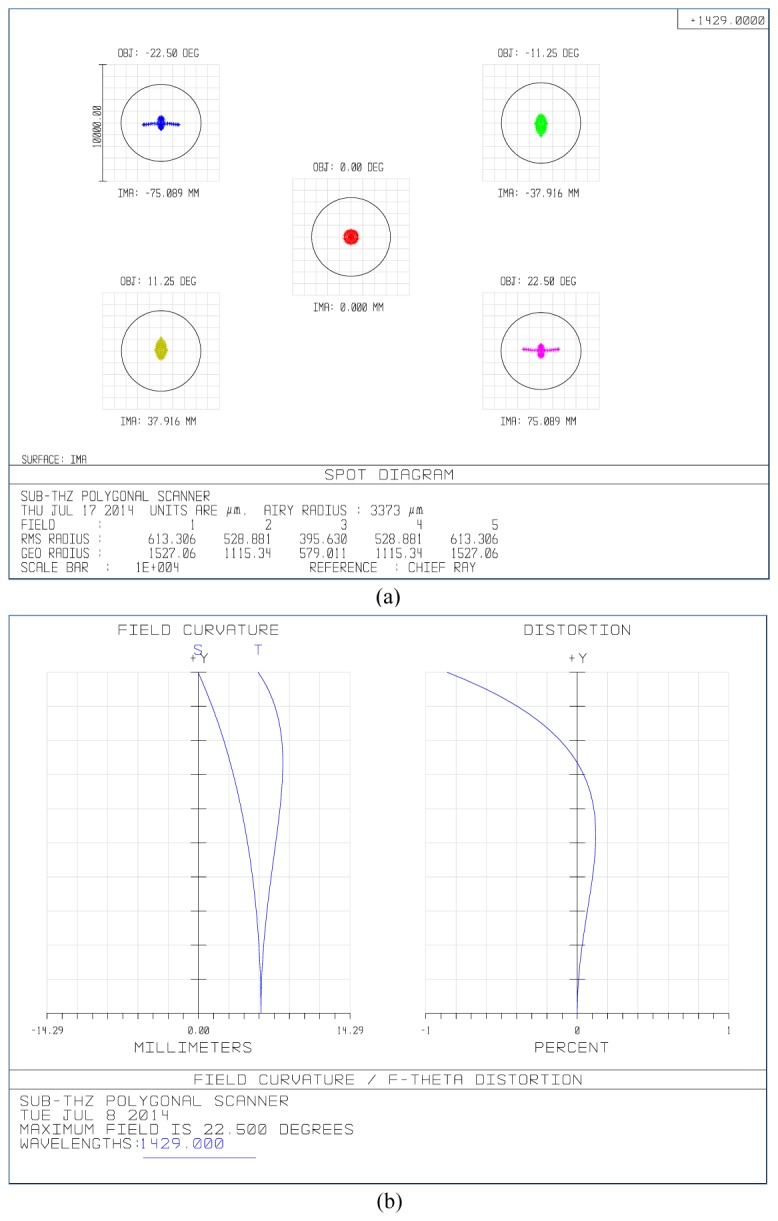
(a) Spot diagram of an f-theta lens (black circles denote the Airy disks, and the units are μm). (b) Field curvature and f-theta distortion of the f-theta lens (the vertical axis units are degrees, and the maximum value is 22.5°).
Figure 1(b) illustrates that the field curvature values in both the sagittal and tangential planes are less than 8 mm, which is only 6 times larger than the source wavelength. Additionally, the result of f-theta distortion analysis shows quite a good linearity (< 0.12%) to the field angle of 18°; however, the distortion value near the full field (22.5°) is abruptly increased to 0.86%.
For estimating a beam spot size with the Huygens point spread function (PSF), the full-width at half-maximum (FWHM) of the beam spot diameter d (or beam waist ω0) was calculated to be 3.44 mm, and its cross-sectional plot is depicted later in Section 4.1 (Fig. 6(b)).
Fig. 6.
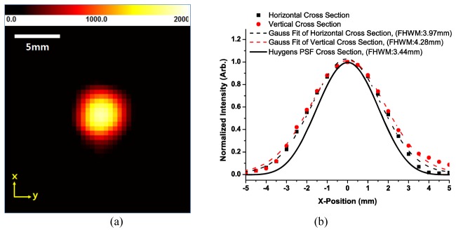
(a) The best focused beam profile at Z = 164 mm and 0° field (40 × 40 pixels2 with 0.5 mm/pixel resolution), where the beam intensity value is given in arbitrary units. (b) The beam cross sections with their Gaussian fit curves and Huygens point spread function (PSF) cross section, which was calculated by the ray-tracing software.
For constructing a pre-objective polygonal mirror scanning system, an f-theta lens as an objective should be combined with a suitably designed polygonal mirror, which can be described by the equations that follow below [17].
Figure 2(a) displays a geometrical configuration of the polygonal mirror with 6 facets, wherein we follow the notation of [17], except for an orientation of the coordinate system. It depicts that the collimated beam with diameter D is incident on the facet ST on the mirror with an offset angle 2β from the Z-axis, and that the reflected beam is parallel to the Z-axis as a scan axis. When the mirror is rotated, the angle of the reflected beam to the scan axis can be varied. The width of the facet ST of the polygonal mirror with N facets can be obtained from the following equation:
| (1) |
where a facet angle is denoted as A = 360°/N, and the radius of its circumscribed circle is given by r. If this beam has an infinitesimal width (D = 0), the full scan angle can be given by ± A. Otherwise, the scan duty cycle η (scan efficiency) can be helpful for describing the scanning performance of the polygonal mirror scanner. It can be defined as the ratio of the useful scan angle (2δ) to the full scan angle ( ± A) of the beam, and obtained by:
| (2) |
Additionally, when the incident beam is positioned to cut through the circumscribed circle at E and F, the angular rotation of the reflected beam is symmetrical about the scan axis. Therefore, the arcs SE and FT are equal. This means that the polygonal mirror scanner is in the midposition, which is characterized by the points P and G. Using the parameters N, β, η, and r, the coordinates of points P and G – (ZP,YP) and (ZG,YG) – can be obtained by the following equations [17]:
| (3) |
| (4) |
| (5) |
| (6) |
When N, β, r, and D are given, the design parameters of the polygonal mirror can be easily determined with Eqs. (1)–(6). Moreover, using Eq. (2) and the scan angle 2δ, r can be deduced as:
| (7) |
For higher scanning speeds, the facet number N of the polygonal mirror should be increased. However, as a result of increasing the facet number, the radius r of the polygonal mirror is also increased in order to maintain the constants D, β, and 2δ. With this consideration in mind, the geometrical configuration was optimized to Fig. 2(b), based on above equations, where N = 4, ST = 180 mm, r = 127 mm, thickness = 110 mm, 2β = 90°, D = 100 mm, and 2δ = 45°.
Fig. 2.
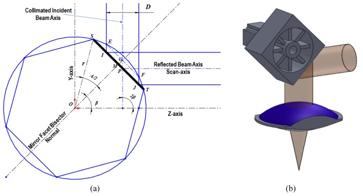
(a) A geometrical configuration of a polygonal mirror (facet number N = 6). (b) Perspective view of the polygonal mirror scanner combined with an f-theta lens and a driving brushless direct current (BLDC) motor (N = 4) at a field angle of 0°.
3. Experimental setup for CW sub-THz transmission imaging
In order to evaluate the performance of this imaging system, a focused beam profile of the polygonal mirror scanner should first be characterized. Figure 3 shows the scanner module on the optical table for the beam profile characterization. Its operation can be described as follows.
Fig. 3.
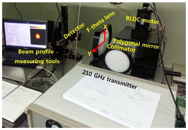
Experimental setup for the characterization of the polygonal mirror scanner, which consists of an f-theta lens and a polygonal mirror (N = 4). BLDC: brushless direct current.
A 210 GHz transmitter (Virginia Diodes Inc., Charlottesville, VA, USA) with an output power of 75 mW and a diverging angle of 18° is used as an illuminating source for which the E-polarization is parallel to a rotor axis of the polygonal mirror. A diverging Gaussian beam from a conical horn (WR-5.1) of the source is collimated by an aspherical PE lens (n = 1.53, focal length = 330 mm, diameter = 164 mm). When the collimated beam arrives on the polygonal mirror, a rotational movement of the polygonal mirror results in the oscillatory beam deflection, which can be effective within the range of the useful scan angle (2δ = 45°). Its scan frequency is dependent on the rotor speed and the facet number of the mirror. For instance, in the case of the facet number N = 4 and the rotor speed = 1200 rpm, the scan frequency is 80 Hz. Moreover, the rotor speed can be increased to 5000 rpm or more, depending on motor performance and especially the data acquisition speed for faster signal processing. By combining the polygonal mirror with the bi-aspheric PE f-theta lens, the deflected beam from the polygonal mirror surface can be focused on the sample surface being scanned with uniform illumination and constant scanning velocity.
With this setup, focused beam profiles at different field angles (Y-positions) and optical axis directions (Z-positions) were measured with a pinhole scanning method, where the Schottky diode detector (responsivity = 2000 V/W; Virginia Diodes Inc.), as the pinhole, on the motorized XY-stage was scanned at a specific Z-position, while the polygonal mirror was fixed at a specific field angle [11]. A beam waist at the best focus can be experimentally obtained by using these beam profiles at different Z-positions.
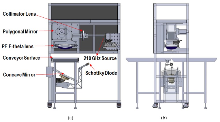
Based on these characterizations of the polygonal mirror scanner, its imaging performance was investigated by constructing the imaging system, which was integrated with the polygonal mirror scanner, conveyor belts, and transmission detection parts. As described earlier, for acquiring sub-THz transmission images, the transmission detection scheme was coupled with the raster-scanned illumination by the polygonal mirror scanner. The optical configuration of the sub-THz transmission imaging system is displayed in Fig. 4 .
Fig. 4.
High-performance continuous-wave (CW) sub-THz transmission imaging system, based on the f-theta scanning lens and the polygonal mirror (N = 4). (a) Right view and (b) front view. PE: polyethylene.
To form a two-dimensional image with the imaging system in Fig. 4, the conveyor belts for sample translation should be incorporated with the line scan illumination provided by the polygonal mirror scanning, similar to the previously reported configuration [12]. The direction of the line scan illumination is equivalent to a vertical direction on the image, and that of the sample translation to a horizontal direction on the image. This imaging setup is commonly used in X-ray inspection systems, wherein a linear detector array works in conjunction with a conveyor belt. In our configuration, two conveyor belts are spaced 15 mm apart for unblocking the transmitted beam through the sample, as depicted in Fig. 4(b).
Along with this optical configuration, the transmitted beams through the sample on the gap of two conveyor belts are consecutively reflected on the concave mirror surface (focal length = 500 mm, diameter = 400 mm), as shown in Fig. 4. The reflected beams from the concave mirror are then collected by a single detector, which is a Schottky diode (with a responsivity of 2000 V/W, Virginia Diodes Inc.) with a WR-5.1 conical horn antenna. The analog signals from the detector are amplified (gain = 500) and filtered (low-pass filter at 30 kHz) by a low-noise preamplifier (SR 560; Stanford Research Systems, Sunnyvale, CA, USA). The amplified signals from the preamplifier are then digitized through a National Instruments data acquisition (NI DAQ) board (NI 6009, National Instruments, Austin, TX, USA), where the trigger signals from a photo sensor are generated by an optical chopper (slot number = mirror facet number) mounted on the rotor of the polygonal mirror.
The number of trigger signals per second is the scan frequency, as described earlier. A digitized data array chopped by trigger signals during every scanning cycle can be regarded as a single vertical line on the image, where the number of array elements can be determined by a sampling rate of the DAQ board. Considering that the scan duty cycle η is around 25% for the polygonal mirror in our setup, and therefore only 25% of signals (on-duty) in one scanning cycle are effective, most of the digitized signals obtained in the cycle are dark signals. Hence, it is appropriate that on-duty signals and their edge signals in the scanning cycle are only displayed as a single vertical line on the images and other off-duty elements are discarded. In the edge region near the on-duty range, the intensity signals are gradually decreased so that the edge signals can also contain useful information.
For constructing a two dimensional image, all vertical lines generated by trigger signals should be drawn together from left to right on the image sequentially, or vice versa. By shifting every vertical line to one direction and adding a new vertical line to the shifted line on the image, transmission images can be continuously constructed with sample movement on the conveyor belt and rotation of the scanning mirror. Here, the intensity values in each vertical line on the transmission image were normalized by those of one specific line – the reference line – that can be measured when no samples are loaded. By introducing the reference line to signal processing, intensity uniformity on the image can be maintained.
4. Results and discussion
4.1 Imaging performance characterization of polygonal mirror scanner
With the setup shown in Fig. 3, focused beam intensity profiles of the polygonal mirror scanner were acquired for its characterization. Since a beam waist can be obtained from the beam intensity profiles at the best focus, the spatial resolution of the imaging system can be estimated by measuring the beam intensity profiles at the focal point. When chief rays of reflected beams from the polygonal mirror were fixed at 5 different field angles (−22.5°, −11.25°, 0°, 11.25°, and 22.5°) corresponding to different Y-positions (−75 mm, −38 mm, 0 mm, 38 mm, and 75 mm), the beam intensity profiles were measured with a pinhole scanning method along 7 different Z-positions from Z = 155 mm to 173 mm with a 3 mm step size, as depicted in Fig. 5 . Each Z-position on an optical axis is the distance from the f-theta lens surface to the pinhole surface of the Schottky diode detector. Each beam profile along the Z-axis at 5 different field angles was obtained with 0.5 mm step scanning over a 20 × 20 mm2 area ( = 40 × 40 pixels2 with 0.5 mm/pixel resolution); these are drawn together in Fig. 5.
Fig. 5.
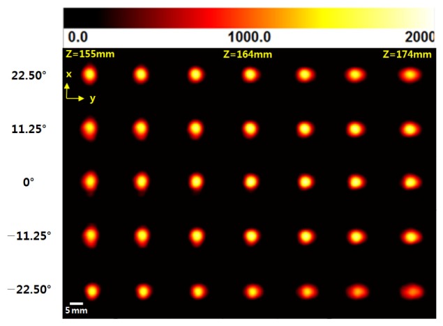
The focused beam intensity profiles measured along the Z-axis at 5 different field angles. Here, the x axis in the beam profiles is the vertical direction shown in Fig. 3, corresponding to a slow scan axis, and the y axis is the horizontal direction shown in Fig. 3, corresponding to a fast scan axis. The color of each pixel in the figures represents the beam intensity, with white denoting maximum intensity, black denoting minimum intensity, and yellow and red denoting the in-between values, as shown in the upper color bar and the legend values. These were sequentially used for illustrating the beam intensity in terms of arbitrary units.
Figure 5 shows that, around Z = 164 mm, beam waists at all field angles are minimized with respect to both vertical and horizontal orientations, whereas the designed value of back focal length was 155 mm. This discrepancy (9 mm ≈6 wavelengths) between the designed and measured focal length can be explained by imperfect Gaussian beams by the source and misaligned collimation prior to the polygonal mirror. As well as this defocus, the astigmatism also appears in high field angles on the beam profiles. Despite these defects, the polygonal mirror scanning module clearly demonstrates diffraction-limited performance within all field angles corresponding to a 150 mm scan range, as expected in the spot diagram of the f-theta lens in Fig. 1(a).
In order to estimate the beam waist at the best focus (Z = 164 mm) and 0° field angle, intensity values from the beam profile (Fig. 6(a) ) were plotted as a vertical cross section and a horizontal cross section in Fig. 6(b). Both cross section plots were fitted with Gaussian functions, as illustrated in Fig. 6(b). Furthermore, as described earlier, the Huygens PSF was also compared with measured cross section plots in Fig. 6(b). Using the fitting curves, FWHM values of the beam waist were estimated to be 3.97 mm (horizontal direction) and 4.28 mm (vertical direction), respectively. These FWHM values are larger than those of the designed beam waist (3.44 mm, Fig. 2(b)). It can therefore be concluded that the expanded beam waist also originates from a similar problem with the case of previous prolonged focal length.
With the average beam waist (ω0 = 4.13 mm), which is averaged from the vertical FWHM and the horizontal FWHM, the Rayleigh range (zR) and depth of focus (DOF) can be easily estimated by the following equation [17]:
| (8) |
In addition to the measurements of the beam waist, the imaging resolution of the polygonal mirror scanner was also evaluated by using a custom-made resolution chart, based on a design pattern of a 1951 USAF resolution chart [18]. The resolution chart depicted in Fig. 7(a) was made of chromium coating patterns on a soda lime glass plate (2.5 mm thickness, 170 × 170 mm2 area). The group number of the patterns ranged from −3 to −1, where each group consisted of 6 elements, as depicted in Fig. 7(a). With the sub-THz transmission imaging system exhibited in Fig. 4, a transmission image of the resolution chart was acquired by translational motion of the resolution chart on the conveyor belt in conjunction with the line scan illumination, as shown in Fig. 7(b). A scanning area of the image was designed to 250 × 180 mm2 ( = 250 × 180 pixels2), whereas the pixel resolution of each direction was designed to 1 mm for a single pixel. On the transmission image of Fig. 7(b), the horizontal direction corresponds to that of sample translation, whereas the vertical direction corresponds to that of beam scanning, where the total number of pixels in the single vertical line includes on-duty signals of 150 pixels and an additional 30 pixels. The additional pixels were intended for displaying the edge region out of the effective scan range because the intensity signals gradually decrease in this region and ultimately fade out. Thus, considering that the vertical length of the resolution chart is 170 mm, the pixel number on its image should be 170 pixels. However, actual values on its image were scaled down to around 150 pixels, and the vertical pixel resolution was scaled up to around 1.15 mm/pixel. This implies that the actual telecentricity at high field angles is not 0° – in other words, not perfectly telecentric. As a result of increased telecentricity, chief rays of focusing beams at high field angles are not perpendicular to the sample surface, such that the overall scanning length is extended from the perfectly telecentric case as designed and the collection efficiency of the transmitted beams at high field angles is decreased. Hence, the spatial resolution per pixel is enlarged from 1.0 to 1.15 mm/pixel. Further, owing to the inefficient collection efficiency at high field angles, the image quality at high field angles was poor, even though normalization by the reference signals was performed, as illustrated in Fig. 7(b). Additionally, it should be noted that the horizontal pixel resolution of the transmission image can be controlled by the conveyor belt speed or image processing algorithm for obtaining an isotropic image.
Fig. 7.
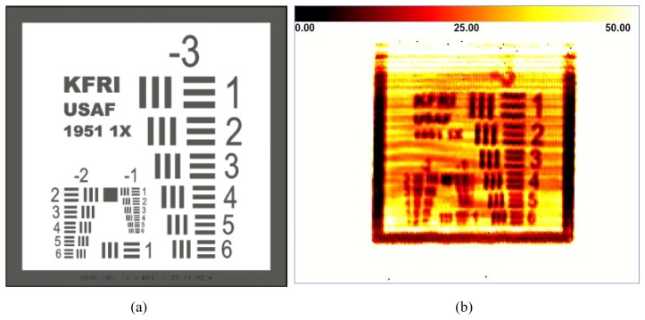
(a) Custom-made resolution chart: chromium patterns on a 2.5 mm thick soda-lime glass. (b) Transmission image (250 × 180 pixels2 with 1.15 mm/pixel resolution) of the custom-made resolution test chart, where intensity values are normalized by the reference signals and the units are percentages. Note that the vertical direction in the transmission images is the fast scan axis, and the horizontal direction is the slow scan axis.
Despite the drawbacks of our imaging system, the image of Fig. 7(b) shows that the fourth elements of the ‘-3′ group can be clearly identified in both orientations so that 2.83 mm line width can be distinguished at 210 GHz. Moreover, the imaging speed is estimated to be 0.32 frames/s over a 250 × 180 pixels2 image, because the scanning frequency is 80 Hz (rotor speed = 1200 rpm). This is almost eight times faster than that of the imaging system by a galvanometer scanner as previously reported [12]. Hence, the transmission imaging system by the polygonal mirror has successfully demonstrated that various desired performance goals – such as high speeds, high resolution, and wide range detection – can be simultaneously accomplished.
4.2 Application to food quality inspection
Based on the characterization results of the imaging system, it was tested in terms of nondestructive food inspection. As food materials, crickets in noodle flour and a wrapped chocolate bar were used. The former is the model sample prepared for foreign body detection, whereas the latter is for food quality inspection. In particular, the crickets in noodle flour were prepared for comparison with the imaging result by the conventional motorized point scanning method, as reported in our prior study [11]. The crickets were buried in noodle flour, which was used to fill a 50 mm diameter circular hole in an aluminum composite panel (100 mm × 100 mm × 8.5 mm), as shown in Fig. 8(a) and 8(b). Both sides of the sample holder were covered with a thin acrylic sheet (thickness: 100 μm). The transmission images of the cricket sample are illustrated in Fig. 8(c) by the polygonal mirror scanning method, and Fig. 8(d) by the motorized point scanning method, respectively [11]. For better visual comparison of the images, the image in Fig. 8(c) was clipped from a transmission image by the polygonal mirror method. The transmission image of Fig. 8(d) clearly shows better resolution than that of Fig. 8(c), because a focusing optics with high numerical aperture can be realized more easily in the motorized point scanning system than in the beam steering system. However, the imaging optics by motorized translational stages has a speed limitation so that much faster beam steering optics ought to be incorporated for high-speed THz imaging. Thus, although the image quality by the polygonal mirror scanning system is somewhat deteriorated because of the limitation of the spatial resolution, its imaging speed can be dramatically increased. For instance, the frame rate for the image of Fig. 8(c) is almost 800 times faster than that of Fig. 8(d), even though the imaging resolution of Fig. 8(d) is 1.5 times better than that of Fig. 8(c).
Fig. 8.
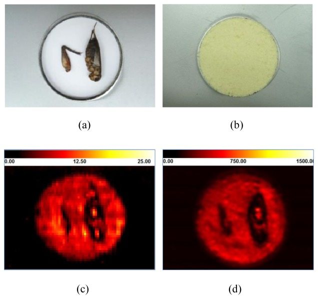
Digital photograph of (a) the crickets (35 mm and 50 mm in length, and 5.5 mm and 7 mm in thickness) and (b) the crickets buried in noodle flour. (c) Clipped image from a continuous-wave (CW) sub-THz transmission image by the polygonal mirror scanning method (full-width at half-maximum [FWHM] of a focused beam: 4.13 mm, Frame rate: 0.32 frame/s over 250 × 180 pixels2 with 1.15 mm/pixel resolution), where a unit of the intensity legend is a percentage. (d) A CW sub-THz transmission image obtained by conventional motorized point scanning method (FWHM of a focused beam: 2.65 mm, frame rate: 0.024 frame/min over 160 × 110 pixels2 with 0.5 mm/pixel resolution), where a unit of the intensity legend is arbitrary.
To confirm the applicability of our imaging system to commercial food product inspection, a chocolate bar in Fig. 9(a) was also tested nondestructively. After obtaining a transmission image of the wrapped chocolate, the PE wrapper of the chocolate was removed. Figure 9(b) and 9(c) show that the partially melted surface can be inspected without opening the packaging. These consequences are, to the best of our knowledge, demonstrated for the first time by using the polygonal mirror scanner for the CW sub-THz imaging system. Furthermore, the speed performances are quite superior to prior CW sub-THz imaging systems and THz time-domain spectroscopy (TDS) imaging systems [9, 12].
Fig. 9.
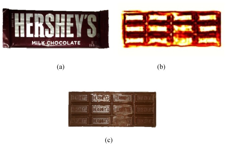
(a) Digital photograph of a wrapped chocolate product (packaging material: polyethylene (PE)). (b) Clipped image from a continuous-wave (CW) sub-THz transmission image by the polygonal mirror scanning method, where the intensity legend was skipped for better comparison with its visible image. (c) Digital photograph of the chocolate (138 mm × 50 mm × 5 mm) after removing the wrapper, where some parts of the chocolate are melted.
5. Conclusion
In summary, a transmission-type, CW, sub-THz imaging system was demonstrated for the first time by using a polygonal mirror scanning method. A single aspheric f-theta lens combined with a polygonal mirror generated a sub-THz line scan illumination with a length of 150 mm, a FWHM of 4.13 mm, and a scanning speed of 80 Hz corresponding to sample translation speed. Despite the drawbacks in optical performance such as astigmatism and non-telecentric focusing, transmission images were continuously acquired at 0.32 frame/s for a 250 × 180 pixels2 image by the line scan illumination on a sample and translation of the sample on conveyor belts. As a result of this performance characterization, the desired performance goals – such as fast scanning speed (80 mm/s), wide range detection (around 150 mm), and high resolution (up to 2.83 mm at 210 GHz) – can be simultaneously accomplished. For demonstrating its applicability to food quality inspection, a few food samples – such as crickets in noodle flour, and a chocolate bar – were successfully tested. In future work, if image processing algorithms and digital signal processing are optimized for enhanced image acquisition, much higher imaging speeds can be obtained [19–21]. By optimizing the collimating optics prior to the polygonal mirror, the beam size should be further minimized so that image quality can be improved. To overcome technical hurdles such as astigmatism and non-telecentricity, the optical design of the f-theta lens and the concave mirror should be improved as well. These results ensure that our imaging system can be commercialized for use in nondestructive food inspection.
Acknowledgments
This work was supported financially by the Korea Food Research Institute in South Korea under a Research Project on Food Safety, and by the IT R&D program of Ministry of Trade, Industry, and Energy (MOTIE)/Ministry of Science, ICT, and Future Planning (MSIP)/Korea Evaluation Institute of Industrial Technology (KEIT).
References and links
- 1.Edwards M., ed., Detecting Foreign Bodies in Food (Woodhead Publishing Ltd, Cambridge, 2004). [Google Scholar]
- 2.Nielsen M. S., Lauridsen T., Christensen L. B., Feidenhans’l R., “X-ray dark-field imaging for detection of foreign bodies in food,” Food Contr. 30(2), 531–535 (2013). 10.1016/j.foodcont.2012.08.007 [DOI] [Google Scholar]
- 3.Edwards M. C., Stringer M. F., The Breakdowns in Food Safety Group , “Observations on patterns in foreign material investigations,” Food Contr. 18(7), 773–782 (2007). 10.1016/j.foodcont.2006.01.007 [DOI] [Google Scholar]
- 4.Lee Y. K., Choi S. W., Han S. T., Woo D. H., Chun H. S., “Detection of foreign bodies in foods using continuous wave terahertz imaging,” J. Food Prot. 75(1), 179–183 (2012). 10.4315/0362-028X.JFP-11-181 [DOI] [PubMed] [Google Scholar]
- 5.Han P. Y., Cho G. C., Zhang X. C., “Time-domain transillumination of biological tissues with terahertz pulses,” Opt. Lett. 25(4), 242–244 (2000). 10.1364/OL.25.000242 [DOI] [PubMed] [Google Scholar]
- 6.Son J.-H., “Terahertz electromagnetic interactions with biological matter and their applications,” J. Appl. Phys. 105(10), 102033 (2009). 10.1063/1.3116140 [DOI] [Google Scholar]
- 7.Son J.-H., ed., Terahertz Biomedical Science & Technology (CRC Press, Boca Raton, FL., 2014). [Google Scholar]
- 8.Kemp M. C., “Millimetre wave and terahertz technology for the detection of concealed threats−A review,” Proc. SPIE 6402, 6402D (2006). 10.1117/12.692612 [DOI] [Google Scholar]
- 9.Jördens C., Koch M., “Detection of foreign bodies in chocolate with pulsed terahertz spectroscopy,” Opt. Eng. 47(3), 037003 (2008). 10.1117/1.2896597 [DOI] [Google Scholar]
- 10.Gowen A. A., O’Sullivan C., O’Donnell C. P., “Terahertz time domain spectroscopy and imaging: emerging techniques for food process monitoring and quality control,” Trends Food Sci. Technol. 25(1), 40–46 (2012). 10.1016/j.tifs.2011.12.006 [DOI] [Google Scholar]
- 11.Ok G., Choi S. W., Park K. H., Chun H. S., “Foreign object detection by sub-terahertz quasi-Bessel beam imaging,” Sensors (Basel) 13(1), 71–85 (2013). 10.3390/s130100071 [DOI] [PMC free article] [PubMed] [Google Scholar]
- 12.Ok G., Park K., Kim H. J., Chun H. S., Choi S. W., “High-speed terahertz imaging toward food quality inspection,” Appl. Opt. 53(7), 1406–1412 (2014). 10.1364/AO.53.001406 [DOI] [PubMed] [Google Scholar]
- 13.Ok G., Kim H. J., Chun H. S., Choi S. W., “Foreign-body detection in dry food using continuous sub-terahertz wave imaging,” Food Contr. 42, 284–289 (2014). 10.1016/j.foodcont.2014.02.021 [DOI] [Google Scholar]
- 14.Goyette T. M., Dickinson J. C., Linden K. J., Neal W. R., Joseph C. S., Gorveatt W. J., Waldman J., Giles R., Nixon W. E., “1.56 Terahertz 2-frames per second standoff imaging,” Proc. SPIE 6893, 68930J (2008). 10.1117/12.764672 [DOI] [Google Scholar]
- 15.Song Q., Zhao Y. J., Sanchez A. R., Zhang C. L., Liu X. H., “Fast continuous terahertz wave imaging system for security,” Opt. Commun. 282(10), 2019–2022 (2009). 10.1016/j.optcom.2009.02.019 [DOI] [Google Scholar]
- 16.Katletz S., Pfleger M., Pühringer H., Vieweg N., Scherger B., Heinen B., Koch M., Wiesauer K., “Efficient terahertz en-face imaging,” Opt. Express 19(23), 23042–23053 (2011). [DOI] [PubMed] [Google Scholar]
- 17.Marshall L. F., ed., Handbook of Optical and Laser Scanning (Marcel Dekker Inc., New York, 2004). [Google Scholar]
- 18.Glynn E. F., “efg's Tech Note: USAF 1951 and Microcopy Resolution Test Charts,”http://www.efg2.com/Lab/ImageProcessing/TestTargets/#USAF1951
- 19.Cho S. H., Lee S. H., Nam-Gung C., Oh S. J., Son J. H., Park H., Ahn C. B., “Fast terahertz reflection tomography using block-based compressed sensing,” Opt. Express 19(17), 16401–16409 (2011). 10.1364/OE.19.016401 [DOI] [PubMed] [Google Scholar]
- 20.Hwang B.-M., Lee S. H., Lim W.-T., Ahn C. B., Son J.-H., Park H., “A fast spatial-domain terahertz imaging using block-based compressed sensing,” J. Infrared, Millimeter, Terahertz Waves 32(11), 1328–1336 (2011). 10.1007/s10762-011-9822-5 [DOI] [Google Scholar]
- 21.Kim K., Lee D.-G., Ham W.-G., Ku J., Lee S.-H., Ahn C.-B., Son J.-H., Park H., “Adaptive compressed sensing for the fast terahertz reflection tomography,” IEEE Trans. THz, Sci. Tech. (Paris) 4, 395–401 (2013). [DOI] [PubMed] [Google Scholar]


