Abstract
Snake-like manipulators with a large, open lumen can offer improved treatment alternatives for minimally- and less-invasive surgeries. In these procedures, surgeons use the manipulator to introduce and control flexible tools in the surgical environment. This paper describes a predictive algorithm for estimating manipulator configuration given tip position for nonconstant curvature, cable-driven manipulators using energy minimization. During experimental bending of the manipulator with and without a tool inserted in its lumen, images were recorded from an overhead camera in conjunction with actuation cable tension and length. To investigate the accuracy, the estimated manipulator configuration from the model and the ground-truth configuration measured from the image were compared. Additional analysis focused on the response differences for the manipulator with and without a tool inserted through the lumen. Results indicate that the energy minimization model predicts manipulator configuration with an error of 0.24 ± 0.22mm without tools in the lumen and 0.24 ± 0.19mm with tools in the lumen (no significant difference, p = 0.81). Moreover, tools did not introduce noticeable perturbations in the manipulator trajectory; however, there was an increase in requisite force required to reach a configuration. These results support the use of the proposed estimation method for calculating the shape of the manipulator with an tool inserted in its lumen when an accuracy range of at least 1mm is required.
Keywords: Medical Robots and Systems, Kinematics, Underactuated Robots
I. INTRODUCTION
Snake-like manipulators with a large, open lumen can offer improved treatment alternatives for minimally- and less-invasive surgeries. One motivating example for this work is the treatment of osteolytic lesions (degraded bone) occurring behind a total hip replacement. This procedure focuses on conditions when the acetabular component is well-fixed and the surgeon does not want to remove it. Current standard-of-care achieves, at most, 50% coverage of the osteolytic lesion [1] due to a lack of dexterous tools. An underactuated, snake-like manipulator has recently been developed for the treatment of these lesions [2], [3]. This manipulator fits through the screw holes in an acetabular component of the implant, improving treatment capabilities to over 94% [3], [4].
Traditional modeling of snake-like manipulators follows constant, or piecewise-constant, curvature [5], enabling closed-form solutions for forward and inverse kinematics. However, for manipulators not exhibiting constant curvature, such as the manipulator in this application, these approaches break down. Dynamic models of these nonconstant curvature manipulators have included internal friction [6]–[8], but do not consider the effect of tools inserted through the manipulator.
The insertion of tools may introduce changes in the response of the manipulator. These inserted tools may increase the effective stiffness, requiring increased force to perform bending. Moreover, inserted tools may change the trajectory the manipulator follows under the same pattern of actuation. This work presents a technique for estimating manipulator configuration from tip position, and examines the effects of a tool inserted through the lumen of a snake-like manipulator. Section II describes the experiments and developed models to compare the manipulator’s performance with and without a tool inserted into the lumen. Section IV identifies the outcome of the experiments, and Section V offers a brief discussion with concluding remarks in Section VI.
II. MANIPULATOR DESCRIPTION
This section briefly reviews the snake-like manipulator, a simple tool, and the modeling procedure used in this work. A full description of the manipulator design and the associated fabrication process can be found in [2], [3]. The relevant kinematic model of the manipulator is presented in [4], [9].
A. Manipulator design
The manipulator is an underactuated, snake-like robot composed of two nested tubes of nitinol, 35mm long with a nominal outer diameter of 6mm and an open lumen with a diameter of 4mm. This sizing enables insertion of the manipulator through the screw holes of a well-fixed acetabular component for less-invasive treatment of pelvis osteolysis during hip revision surgery (Fig. 1). A specific notch pattern allows single-plane bending achieved through pull-pull activation of solid stainless steel cables embedded in drive channels between the nested tubes.
Fig. 1.
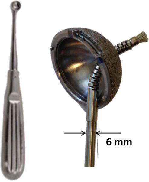
Comentional rigid tool, a curette, (left) and a rotary brush through the lumen of the manipulator inserted into an acetabular implant (right).
A 3mm diameter, 1mm lead ball screw assembly (Steinmeyer, Germany) actuates the cables, pulling them to create tension. A precision miniature 44.5N load cell (Honeywell, Columbus, OH) placed in series with the cable measures the cable tension. Custom hardware and software interface the 1.6W 10mm brushed DC motors (Maxon Motors, Switzerland) driving the ball screw assembly with a general purpose field-programmable gate array and a real-time Linux computer through an IEEE 1394 interface [9]-[11]
A series of 27 pin joints geometrically defined along the length of the manipulator describe the kinematic configuration, . This approach allows sufficient flexibility to model the nonconstant curvature behavior of the robot. A series of points, pj for j ∈ {1, 2, … , 58}, in the xz-plane along the length of the manipulator exist as a function of (Fig. 2).
Fig. 2.
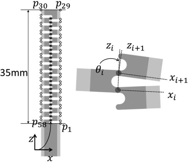
The kinematics of the manipulator identifying the pin joints (*) and points pj (o) on the manipulator. Positive rotation, θi, occurs about the y axis (into the page) at each pin joint (9).
B. Tooling
A simple rotary brush was one of the tools developed for insertion through the lumen of the manipulator (Fig. 1). The tool is composed of a long, 303 stainless steel rod of 3.175mm diameter to transmit torque. A 302 stainless steel extension spring with an outer diameter of 3.175mm using 0.46mm diameter wire attaches a diamond-tipped abrasive brush to the steel rod. The spring provides effective torque transmission to the brush from an external motor, allowing the brush to break up hard tissue occurring inside the lesion. Moreover, the spring is capable of a tighter bend radius than the minimum manipulator bend radius, ensuring the tool does not have a substantial impact on the manipulator capabilities.
C. Modeling
Since the manipulator does not follow constant curvature, predicting the manipulator configuration from tip position uses an energy minimization approach. The minimization solves
| (1) |
subject to the constraint
| (2) |
and bounded by
| (3) |
where is the estimated configuration, θi is the rotation about the ith pin joint, and p̃ is the estimated tip position from the estimated configuration. The constraint function (2) ensures that the tip is pinned at the given position; if this constraint is not followed, then the optimization will result in a constant curvature shape, which is not appropriate for this manipulator.
III. TESTING
A series of two tests were run on the manipulator. The first bent the manipulator with no tool inserted through the lumen; the second test bent the manipulator with the tool inserted through the lumen. A single test procedure consisted of three iterations of the following steps:
1) Fully slack the “left” cable and move the “right” cable to the zero position.
2) Bend the “right” cable a small amount. Record an image from an overhead camera, the actuator position, and the tension in the cable.
3) Repeat 1 and 2 until a maximum allowable tension of 22.2N is measured in the “right” cable.
4) Repeat 1 and 2, only releasing tension in the drive cable, until the “right” cable reaches the zero position.
5) Fully slack the “right” cable and move the “left” cable to the zero position.
6) Repeat 3 and 4 for the “left” cable.
The tests were run sequentially and the actuator position was zeroed once for the set of tests. Test 1 consisted of 180 images, and test 2consistedof 182 images (approximatley 15 steps to bend or unbend the manipulator per side). This test series did not consider position control of the manipulator, but bent to a specific maximum force. The choice of limiting cable tension rather than motor encoder position ensures a large range of motion while maintaining a factor of safety of 2 to protect the load cell.
A previously validated piecewise-rigid 2D/3D registration routine (maximum tip error of 0.8mm) defined the ground-truth kinematic configuration of the manipulator from each static image recorded during the test procedure [12]. The registration routine optimized the similarity between a projected image of the known 3D model of the manipulator with estimated configuration and the recorded static image to define the kinematic configuration, .
The tip position was measured from the static images and used as the constraint in the energy minimzation. Comparisons between the model-estimated manipulator configuration for each of the tests and the ground-truth configuration identified the accuracy of the model. The accuracy was defined as the Euclidean distance between actual and estimated points along the length of the manipulator, . An unpaired t-test identified any significant differences (p < 0.05) between the energy minimization for the manipulator with and without a tool.
The effects of the tool on the manipulator can be considered in two specific realms: 1) the kinematic response (i.e., the trajectory of the manipulator) and 2) the force response (i.e., the relationship between force to string length and/or position). A comparison between the trajectories as measured through the images of the manipulator with and without the tool identified any kinematic differences tool insertion may have on the manipulator; specifically, does the nonconstant curvature bending of the manipulator change with and without a tool in the lumen. Evaluating the relationship between string length and force (i.e., cable tension) showed how the tool affects the manipulator through the addition of internal forces.
IV. RESULTS
The energy minimization predicts the manipulator configuration with an average error of 0.24 ± 0.22mm and an average maximum error of 0.43 ± 0.27mm between the 58 points identified on the manipulator (Fig. 3(a)). In two images, maximum error exceeds lmm. When a tool is inserted in the lumen, the errors are comparable to no tool. There is an average error among the 58 points identified along the manipulator of 0.24 ± 0.19mm and a maximum error of 0.42 ± 0.23mm when the tool is inserted in the lumen (Fig. 3(b)). A t-test identified no significant difference between the energy minimization error with or without a tool (p = 0.81).
Fig. 3.
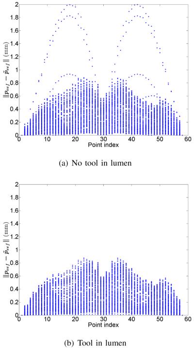
Errors due to energy minimization along the length of the manipulator compared to the ground truth.
The overall trajectory for each test is approximately the same; however, there is a small difference on bends to the left (Fig. 4). As testing progresses, there may be some small plastic deformation in the steel cable. This would then require a greater change in string length to achieve the same force. However, the opposite effect is observed when the tool is attached. Specifically, a smaller change in string length is required to see the same amount of force (Fig. 5).
Fig. 4.
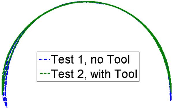
Tip position of the manipulator throughout the experiments as measured by the 2D/3D registration routine. Note the slight hysteresis on bends to the left. When the tool is inserted, the manipulator tip follows approximately the same trajectory, except it does not achieve as much bending under the same maximum allowable tension of 22.2N.
Fig. 5.
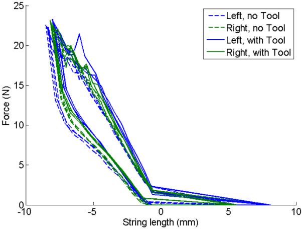
Plot of force vs string length for left and right bends. A string length of 0 represents no bending. while a negative string length indicates pulling on the cable to bend the manipulator. The manipulator with the tool requires a larger force to reach same string length (i.e., the overall stiffness of the system increases with a tool in the lumen).
V. DISCUSSION
This work presents the impact of inserting a tool through a lumen in a snake-like manipulator. Previous research focused only on the manipulator without consideration of tools inserted through the lumen. The results indicate that tools, specifically those with less stiffness than the manipulator, will impact the manipulator response to actuation. Although this work focuses on a single, specific tool, it is likely that this generalizes to all tools, especially those with lesser stiffness than the manipulator. Of note, all tools used for the envsioned awtication will have less stiffness than the manipulator.
The energy minimization procedure described in this work (1) offers an appropriate technique for estimating the manipulator configuration given the tip position. In the case without a tool, the minimization procedure saw two cases with errors over 1.00mm. In these situations, the ground-truth manipulator configuration estimated from the 2D/3D image-based registration was not perfect, leading to increased error (Fig. 6). The total system error (2D/3D image-based registration combined with the energy minimization) exceeds 1.00mm; in the envisioned awlication for the treatment of hip osteolysis, this error is acceptable as the manipulator will be “sweeping” a volume and sub-millimeter accuracy is not required.
Fig. 6.
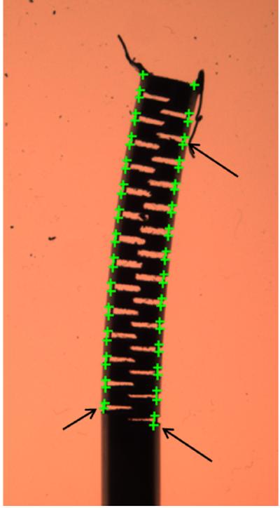
Example of imperfect image-based registration. Note the errors at the base of the manipulator and along the length (large differences are highlighted with arrows) where the green “+” do not match with the notch of the manipulator.
The force profile of the manipulator with and without tools inserted into the lumen suggests a stiffening of the manipulator when a tool is inserted (Fig. 5). Using the point of maximum force (Fmax) and string length (max) as a measure of stiffness , the stiffness with a tool is 2.65N/mm compared to 2.00N/mm without a tool. The sequential nature of the testing also realizes the potential for plastic cable deformation as the third test required less force than the first test to achieve the same string length; effective pre-stretching cable routines can help to mitigate this error in the future. A 0.254mm diameter solid cable actuated the manipulator during testing; the drive cable channels would allow a larger diameter cable (up to 0.305mm diameter) to pass through. Using a larger diameter cable would reduce the amount of plastic/elastic deformation. However, a larger drive cable may influence internal friction, which is known to have an impact on the manipulator dynamics [6]-[8].
This work assumes accurate tracking of the manipulator tip is possible. At p:esent, this tip-sensing occurs using image feedback. However, in the surgical scenario, this is impractical due to the large radiation dose to the patient from continuous x-ray imaging; nonetheless, intermittent image analysis may be used as feedback to a control loop for the maniplator. Other real time tip-sensing strategies, such as electromagnetic tracking (e.g., Aurora, NDI, Inc., Waterloo, CA), or acoustic tracking (e.g., ultrasound), may be employed to track the tip of the manipulator. Moreover, additional work such as [9] offers a potential for estimating tip position as a function of string length without assumptions on constant curvature. This app:oach is verified for the manipulator without a tool, but may also work when a tool is inserted through the lumen.
Future work should investigate how the manipulator moves when the tool is actuated. The tool developed in this work is designed to be driven by an external motor, transmitting torque through the combination rigid and flexible drive shaft As the flexible drive shaft turns and the tool interacts with the environment, it is likely that there will be a more significant impact on the manipulator movement. Only a single cable was tensioned during the experiments in this work; it is possible that co-contraction (i.e., simultaneous tensioning of both cables) could reduce the effect of the tool.
VI. CONCLUSIONS
Many existing efforts seek to characterize snake-like manipulators without considering tools through the lumen. This work presented a case-study of how a tool inserted through the lumen of a snake-like manipulator will affect the response when the tool has less stiffness than the manipulator. In this case, the tool had a minor impact on the overall stiffness of the system as measured by the requisite force to achieve a specific change in cable length, and resulted in small deviations in trajectory. Future testing of additional tools, and actuating the tools inside the manipulator lumen, will further improve our understanding of the manipulator response, which is effectively modeled using an energy minimization approach.
ACKNOWLEDGMENT
We thank Dr. Michael Kutzer, Dr. Matthew Moses, and Mr. Allen Hayes for their design of the actuation unit.
Footnotes
This work was supported in part by NIH Grant 1R01EB016703 and JHU/APL internal funds.
REFERENCES
- [1].Engh CA, Jr., Egawa H, Beykirch SE, Hopper RH, Jr., Engh CA. The quality of osteolysis grafting with cementless acetabular component retention. Clin Orthop Relat Res. 2007 Dec;465:150–154. doi: 10.1097/BLO.0b013e3181576097. [DOI] [PubMed] [Google Scholar]
- [2].Kutzer MDM, Segreti SM, Brown CY, Armand M, Taylor RH, Mears SC. Design of a new cable-driven manipulator with a large open lumen: Preliminary applications in the minimally-invasive removal of osteolysis. Proc. IEEE Int Robotics and Automation (ICRA) Conf. 2011:2913–2920. [Google Scholar]
- [3].Murphy RJ, Kutzer MDM, Segreti SM, Lucas BC, Armand M. Design and kinematic characterization of a surgical manipulator with a focus on treating osteolysis. Robotica. 2014 in press. [Google Scholar]
- [4].Murphy RJ, Moses MS, Kutzer MDM, Chirikjian GS, Armand M. Constrained workspace generation for snake-like manipulators with applications to minimally invasive surgery. Robotics and Automation (ICRA), 2013 IEEE International Conference on. 2013 May;:5341–5347. [Google Scholar]
- [5].Webster RJ, Jones BA. Design and kinematic modeling of constant curvature continuum robots: A review. The International Journal of Robotics Research. 2010 Nov;29(13):1661–1683. [Online]. Available: http://dx.doi.org/10.1177/0278364910368147. [Google Scholar]
- [6].Jung J, Penning RS, Ferrier NJ, Zinn M. A modeling approach for continuum robotic manipulators: Effects of nonlinear internal device friction. Intelligent Robots and Systems (IROS), 2011 IEEE/RSJ International Conference on. 2011 Sep;:5139–5146. [Google Scholar]
- [7].Jung J, Penning RS, Zinn MR. A modeling approch for robotic catheters: effects of nonlinear internal device friction. Advanced Robotics. 2014:1–16. 0. 0. in press. [Online]. Available: http://www.tandfonline.com/doi/abs/10.1080/01691864.2013.879371. [Google Scholar]
- [8].Moses MS, Murphy RJ, Kutzer MDM, Armand M. Modeling cable and guide channel interaction in a high-strength cable-driven continuum manipulator. Transaction on Mechantronics. 2014 doi: 10.1109/TMECH.2015.2396894. submitted. [DOI] [PMC free article] [PubMed] [Google Scholar]
- [9].Murphy RJ, Otake Y, Taylor RH, Armand M. Predicting kinematic configuration from string length for a snake-like manipulator not exhibiting constant curvature. Robotics and Automation (ICRA), 2014 IEEE International Conference on. 2014 accepted. [Google Scholar]
- [10].Thienphrapa P, Kazanzides P. A distributed i/o low-level controller for highly-dexterous snake robots. Biomedical Circuits and Systems Conference, 2008. BioCAS 2008. IEEE. IEEE. 2008:9–12. [Google Scholar]
- [11].Thienphrapa P, Kazanzides P. A scalable system for real-time control of dexterous surgical robots. Technologies for Practical Robot Applications, 2009. TePRA 2009. IEEE International Conference on. IEEE. 2009:16–22. [Google Scholar]
- [12].Otake Y, Murphy RJ, Kutzer MDM, Taylor RH, Armand M. Piecewise-rigid 2d-3d registration for pose estimation of snake-like manipulator using an intraoperative x-ray projection. Proc. SPIE Medical Imaging. 2014 Mar;9036:90. 360Q–90 360Q–6. [Online]. Available: http://dx.doi.org/10.1117/12.2043242. [Google Scholar]


