Abstract
We investigated to what degree and at what rate the ultimate intrinsic (UI) signal-to-noise ratio (SNR) may be approached using finite radiofrequency detector arrays. We used full-wave electromagnetic field simulations based on dyadic Green’s functions to compare the SNR of arrays of loops surrounding a uniform sphere with the ultimate intrinsic SNR (UISNR), for increasing numbers of elements over a range of magnetic field strengths, voxel positions, sphere sizes, and acceleration factors. We evaluated the effect of coil conductor losses and the performance of a variety of distinct geometrical arrangements such as “helmet” and “open-pole” configurations in multiple imaging planes. Our results indicate that UISNR at the center is rapidly approached with encircling arrays and performance is substantially lower near the surface, where a quadrature detection configuration tailored to voxel position is optimal. Coil noise is negligible at high field, where sample noise dominates. Central SNR for practical array configurations such as the helmet is similar to that of close-packed arrangements. The observed trends can provide physical insights to improve coil design.
Keywords: magnetic resonance imaging, parallel imaging, signal-to-noise ratio, ultimate intrinsic signal-to-noise ratio, dyadic green’s function, radiofrequency coil performance
INTRODUCTION
The introduction of receive arrays into the field of magnetic resonance imaging (MRI) in the late 1980s revolutionized MR signal reception (1). With appropriate combination of the signals from the individual elements, receive arrays can provide the high signal-to-noise ratio (SNR) of small surface radiofrequency (RF) coils over extended fields-of-view (FOVs). In addition to improving conventional imaging, receive arrays have enabled the use of parallel imaging techniques, which allow reconstruction of MR images from under-sampled datasets (2–4). As the efficiency of parallel imaging and the achievable acceleration factors depend on the number of coil elements in the receive array, the number of receive channels in MR systems has increased over time, up to a current maximum of 128 (5). However, the question of how many elements are enough is still unanswered.
Since time, cost and complexity limit the practical number of receive channels and prototype arrays that can be built, simulations are a feasible alternative approach to investigate the effect of increasing the number of coil elements on imaging performance. Numerical techniques, such as the finite difference time domain technique, are widely used to simulate RF coil performance based on accurate electromagnetic (EM) field calculations (6–10). While the results show good agreement with experiments, the numerical complexity of the computations increases with the number of coil elements. Therefore, this approach is not well suited to testing multiple array configurations with large numbers of coil elements. Furthermore, this type of analysis gives no indication of whether a particular receive array is optimal, or if there is room for improvement.
The upper limit on the SNR achievable for a given imaging sample, independent of the particular coil geometry, has been investigated in the case of simple objects with uniform electrical properties (11–14). These studies provided valuable physical insights by showing the behavior of the ultimate intrinsic SNR (UISNR) with respect to main magnetic field strength, acceleration factor and imaging FOV.
Wiesinger et al. (14–16) simulated parallel imaging performance of receive arrays with an increasing number of finite circular loops closely packed around a uniform sphere and compared it with the UISNR. Their preliminary results suggested that 32 coils could be enough to approach the best possible performance in the center of the object. Another study showed that as many as 128 “cylindrical window” coils may be needed to obtain similar results in the center of a dielectric cylinder (17). The receive efficiency was lower in the second case because the object-coil configuration was different and a more realistic noise model was used, which accounted for losses due to the coil conductors, the receive circuit and the conductive shield of the MR system.
Lattanzi and Sodickson (18) recently proposed an electrodynamic simulation framework, based on dyadic Green’s functions (DGF), which enables calculation of SNR in a homogeneous spherical sample for finite arrays of loop coils and in the ultimate intrinsic (UI) case. DGF were also used in one of the first investigations of UISNR in homogeneous cylindrical samples (12). While previous approaches to calculating UISNR in a sphere were based on a direct expansion of EM field inside the object (14–16), the DGF method uses a mode expansion of basic current modes defined on an external surface to derive the EM field distribution inside the object. With this approach, it is possible to model the current patterns of actual coils by appropriate linear combinations of the current modes, and to easily compare the corresponding SNR with the UISNR, which is obtained by performing an unconstrained matched-filter combination of all the current modes (18). As the EM field expansion starts from coils’ current patterns, in the DGF framework it is straightforward to incorporate coil conductor losses (coil noise), modeled as Johnson noise, in the SNR calculation. Note that coil noise can be simulated also with other SNR calculation approaches, but requires deriving coil-specific resistance models (15,19). The DGF simulation framework also enables calculation of the ideal surface current patterns by applying the optimal weights associated with the UISNR to the current modes (18).
In this work, we used the DGF simulation framework to investigate the SNR performance of RF coil arrays with respect to the UISNR as a function of the number of coil elements in the case of a uniform dielectric spherical sample. We looked at the balance between coil noise and sample noise, and explored a large parameter space, varying main magnetic field strength, voxel position, acceleration factor, and sphere size. Over the past years, an interesting body of work on this subject has been presented at conferences (16,17) and compiled in doctoral theses (15,20). The aim of this work is to present a comprehensive study that validates these previously established concepts and describes new results, framing them within a unifying set of physical insights. We also provide new practical insights for RF engineers, by comparing the performance of different array geometries with the same number of coils, for various acceleration factors and in multiple imaging planes.
THEORY
The DGF formalism (21) allows calculation of the full-wave electric field generated by a spatial current distribution J(r′) as:
| [1] |
where Ḡ is the branch of DGF corresponding to the region specified by r, ω is the operating frequency, μ0 is the permeability of free space, and r′ is the location of the current source. The corresponding magnetic field can be derived using Maxwell’s equations:
| [2] |
If we constrain the current to flow on a spherical surface of radius b, we obtain:
| [3] |
where r (radial), θ (polar), and φ (azimuthal) are spherical coordinates and K is the surface current density, which can be expressed as a weighted sum of basic current modes:
| [4] |
Here l and m are the expansion coefficients, Xl,m is the vector spherical harmonic, and are the series expansion coefficients representing magnetic (i.e., divergence-free) and electric (i.e., curl-free) dipole components, indicated with super script M and E respectively. From Eq. [1], we can then calculate the EM field for each basic mode (Appendix A).
The UISNR is the best possible SNR independent of coil geometry and can be calculated by performing an SNR-optimal weighted combination of the contributions of the basic modes in Eq. [4], effectively treating them as the current patterns of individual coil elements in a hypothetical infinite array (Appendix B):
| [5] |
Here M0 is the equilibrium magnetization, ω0 is the Larmor frequency, kB is the Boltzmann constant, Ts is the absolute temperature of the sample, S is the sensitivity matrix, which contains the complex receive sensitivities associated with each mode at the target position as well as all the aliased positions, and Ψmode is the modes’ noise covariance matrix. The “0,0” subscript indicates the diagonal element of the matrix in parenthesis with an index associated with the target position r0.
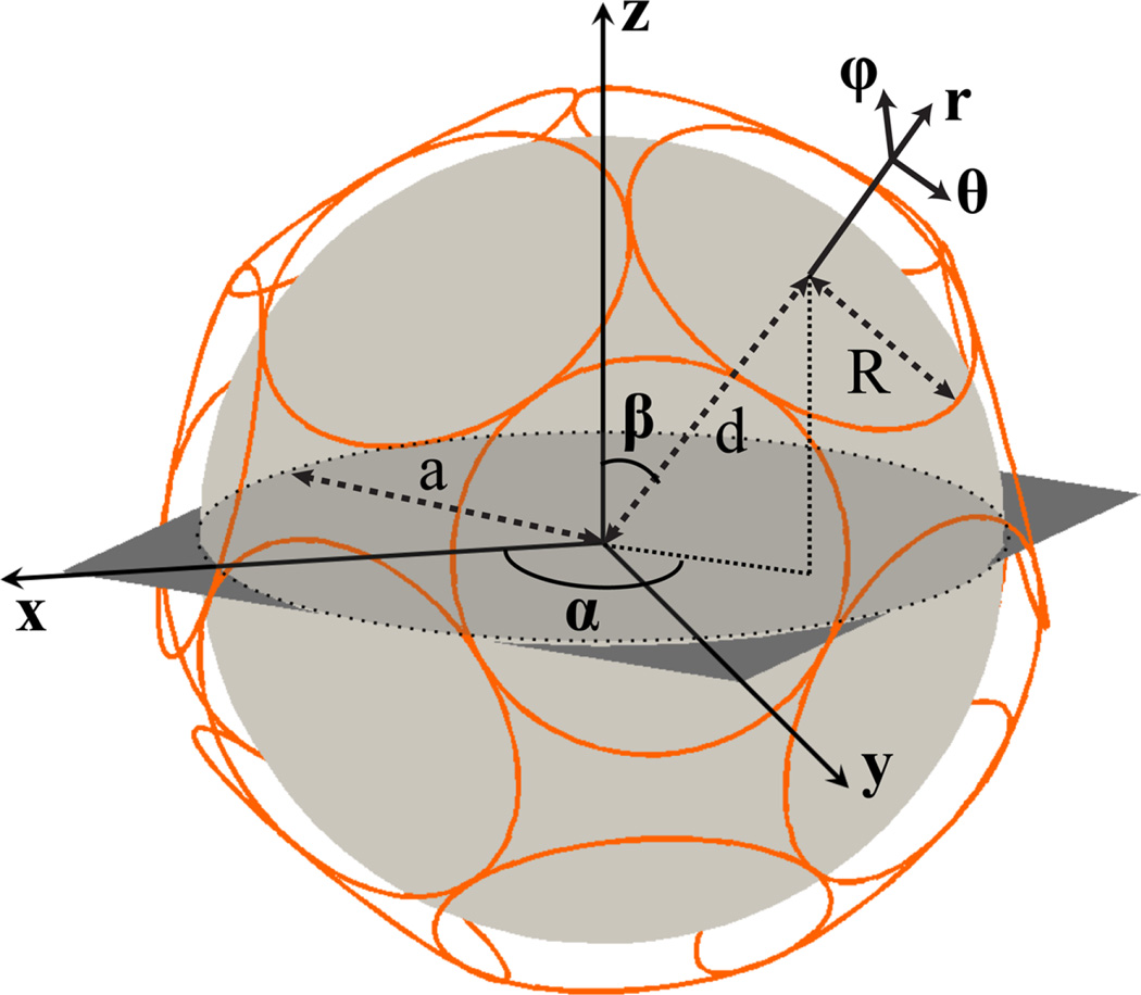
The SNR of particular RF coils can be simulated within the same DGF theoretical framework by applying appropriate weighting coefficients to the basic modes, to constrain the net current to flow exclusively along patterns corresponding to coil conductors. For the case of circular loop coils (Fig. 1), only magnetic dipole components contribute and the combination weights can be found analytically (18):
| [6] |
α, β, and d in this equation define the angular position and radial offset of the center of the coil with respect to the center of the sphere (Fig. 1), R is the radius of the coil and is a spherical harmonic. The receive sensitivity and the noise covariance matrix elements for finite arrays of circular loop coils are obtained by applying the combination weights in Eq. [6] to the corresponding expressions for the modes:
| [7] |
The SNR of the array is then calculated as for the ultimate case, but replacing the quantities in Eqs. [B.1] and [B.4] with those in Eq. [7]. In addition to the intrinsic thermal noise due to the presence of the sample (sample noise), coil noise can be included in the SNR calculation as an extra term added to the diagonal elements of the coils’ covariance matrix (Appendix B).
Figure 1. Schematic representation of a 16-element array of circular loop coils closely packed around a spherical sample.
Relevant quantities describing the geometry are shown. Circular loop coils are arranged on a spherical surface at distance from the center of the sample.
METHODS
We used an in-house DGF simulation tool (18) to calculate SNR and g-factor (3) on transverse and sagittal planes through the center of a uniform sphere (Fig. 1) with electrical properties of the human brain (Table 1). In all cases, the current distribution (Eq. [3]) was defined on a spherical surface concentric with the object and at a distance of one centimeter from the surface of the object. We modeled receive coil arrays of identical circular loop coils, assuming copper conductors with electric conductivity equal to 58 × 106 S/m and thickness equal to the skin depth at the operating frequency associated with each magnetic field strength.
Table 1.
Dielectric Properties of Average Brain Tissue.
| Bo (T) | 1.5 | 3.0 | 7.0 | 9.4 |
|---|---|---|---|---|
| Larmor Frequency (MHz) | 63.9 | 127.7 | 298.1 | 400.2 |
| Dielectric constant εr | 87.9 | 63.1 | 52 | 49.7 |
| Conductivity σ (1/Ωm) | 0.39 | 0.46 | 0.55 | 0.60 |
Various coil array designs were simulated: array elements closely packed around the object with no overlap between them (closely packed) and partially overlapped (overlapped), a geometrical arrangement with no loops surrounding what would be the neck and face regions in a head coil (helmet), and array elements completely surrounding the object in the azimuthal direction but not covering the top and bottom regions of the sphere (open-poles). The “helmet” array was adapted from the 48-element closely packed arrangement (Fig. 5) by removing elements in the neck and face region, whereas the “open-poles” array was constructed by staggering three rows of 11, 11, and 10 coils. In the “helmet” and “open-poles” arrays, the coil elements covered approximately 67% and 47%, respectively, of the spherical surface where the current distribution was defined. Except in the case of the “closely packed” array, the radius of the individual elements was adjusted to obtain an overlap (with respect to coil diameter) of approximately 15% between neighboring coils. All arrays were made of 32 identical elements, but the coil radius changed based on the geometrical arrangement: 3.0 cm for “closely packed,” 3.9 cm for “overlapped,” 3.2 cm for “helmet,” and 3.4 cm for “open-poles” designs, respectively.
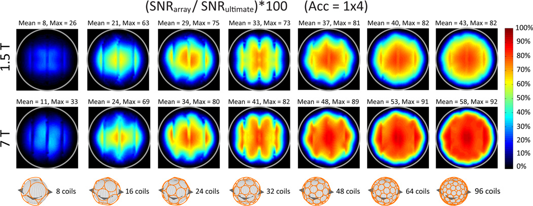
Figure 5. Coil performance maps for a transverse plane evaluated at different field strengths and for an increasing number of loop coils closely packed around a spherical sample with 8.4 cm radius, for the case of 4-fold accelerated parallel imaging.
Each voxel shows the SNR of the array normalized by the corresponding ultimate intrinsic SNR. Coil noise was included in the calculation of the SNR of the arrays. Mean and maximum values are reported above each map. The gray circle indicates the surface of the sphere.
Coil performance was assessed as a percentage of the ultimate performance, for increasing number of coil elements, main magnetic field strength, sphere size, and acceleration factor. The number of coils ranged from 8 to 96, which is the largest number of coils ever used in practice for a head array (22). Calculations were implemented in MATLAB (MathWorks, Natick, MA) and an expansion order of lmax = 65 was used to ensure convergence of the UISNR calculation for every position in the FOV.
RESULTS
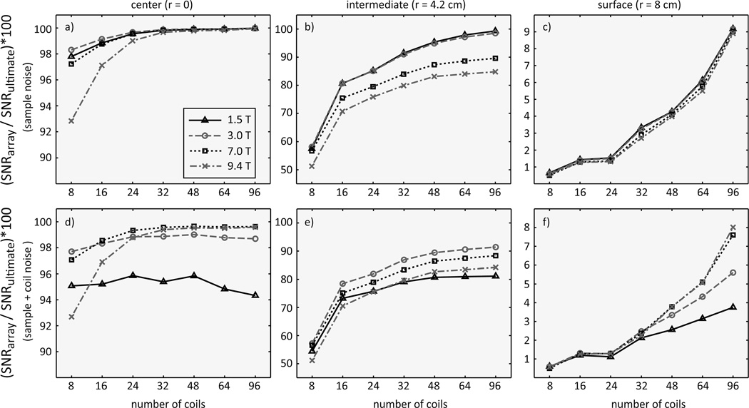
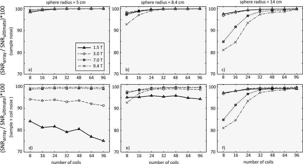
When coil noise was not considered, the SNR of the array in the center of the object rapidly approached the UISNR with increasing number of coils for all magnetic field strengths [Fig. 2(a)]. At 1.5 T and 3 T, nearly 100% performance could also be achieved at a considerable distance from the center of the sphere if 64 or 96 coils were used [Fig. 2(b)]. Although coil SNR was higher near the surface of the sphere, the corresponding coil performance was substantially lower [Fig. 2(c)], because the UISNR grows exponentially as the voxel location approaches the surface (13,16). When resistive losses in the conductors (Appendix B) were included in the SNR calculation [Fig. 2(d–f)], coil performance was largely unaffected at 7 T and 9.4 T, whereas it decreased with increasing number of coils and did not approach the ultimate limits at lower magnetic field strengths. At the center, this effect became more dominant for a smaller sample [Fig. 3(d)], whereas it disappeared for a larger sample [Fig. 3(f)], which was expected given the increased sample noise in larger objects.
Figure 2. Array SNR normalized by the corresponding ultimate intrinsic SNR as a function of number of coils, for various main magnetic field strengths and voxel positions (r) inside a homogeneous sphere with 8.4 cm radius.
Ultimate intrinsic SNR can be approached closely with a sufficient number of coils for a voxel in the center of the sphere (a). Array performance with respect to the ultimate limits decreases for voxel positions closer to the surface of the sample (b, c). Including coil noise contributions to the array SNR further reduces performance with respect to the best possible SNR, especially for larger number of coils and lower main magnetic field strength (d–f). Note that the vertical axis limits are optimized for each plot.
Figure 3. Array SNR normalized by the corresponding ultimate intrinsic SNR for a voxel in the center of a uniform spherical phantom (r = 0) as a function of number of coils, for different main magnetic field strength and sample size.
SNR performance at 1.5 T and 3 T is almost unchanged for different sphere radii (a–c). SNR performance at 7 T and 9.4 T increases as the size of the phantom decreases and it is not significantly affected by the inclusion of coil noise in the SNR calculation (d–f). At 1.5 T and 3 T, coil noise significantly affects performance and becomes more dominant as the number of coils increases (d, e). However, when the sphere size is large, sample noise is higher and dominates even at 1.5 T and 3 T (f).
If only sample noise was considered in the SNR calculation, coil performance at the center increased with magnetic field strength in the case of a 5 cm radius sphere [Fig. 3(a)], whereas it decreased with magnetic field strength in the case of larger objects [Fig. 3(b,c)]. This can be explained by the modest skin depth at high frequency [also shown in Fig. 10 in Ohliger et al. (13)] that prevents effective field penetration into central regions. Figure 4 shows that the contribution of coil noise to array performance was more prominent for a larger number of coils and at lower magnetic field strength, and increased as the voxel position approached the surface of the sphere.
Figure 4. Array SNR normalized by the corresponding ultimate intrinsic SNR as a function of voxel position for different main magnetic field strength and number of coils.
Voxel position is reported as a percentage of the sphere radius. The performance of an 8- and 96-element array of loop coils closely packed around a spherical sample with 8.4 cm radius is plotted with and without coil noise in the SNR calculation. The effect of coil noise is larger for the 96-element array and increases as voxels approach the surface of the sphere. For a voxel half way between the center and the surface of the sphere (i.e., 50% of FOV), coil noise reduces SNR at 1.5 T (a) and at 3 T (b), whereas its contribution is negligible at 7 T (c).
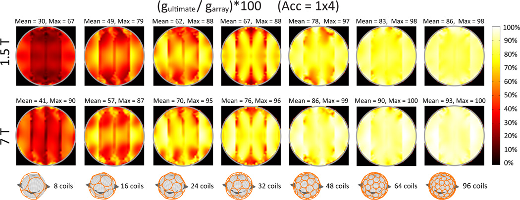
In Fig. 5, coil performance maps (23) display for each voxel of a transverse FOV the SNR of the array divided by the corresponding UISNR. Overall coil performance increased as the number of coil elements was increased and was higher at 7 T than at 1.5 T. Figure 6 shows array encoding efficiency in terms of g-factor for the same cases as in Fig. 5. The g-factor, by definition greater than or equal to one, is a measure of the spatially varying noise amplifications associated with parallel imaging reconstructions and depends on the relative distinctness of coil sensitivity functions (24). At 1.5 T, the ratio of the lowest possible g-factor to the g-factor of the finite arrays was smaller than at 7 T, indicating that, as expected, the coils were more efficient in accelerating image acquisition at higher frequencies. Note that a 96-element array was almost as efficient as an array with an infinite number coils in performing 4-fold linear accelerations at 7 T for a spherical sample with an 8.4 cm radius.
Figure 6. Array efficiency in performing 4-fold linear accelerations as a percentage of the optimum, for different number of coil elements and main magnetic field strength, for a transverse plane through the center of the object.
Each pixel in the map shows the ultimate intrinsic g-factor as a percentage of the array g-factor. Mean and maximum values are reported above each map. Arrays were formed of circular loop coils closely packed around a uniform spherical sample with 8.4 cm radius.
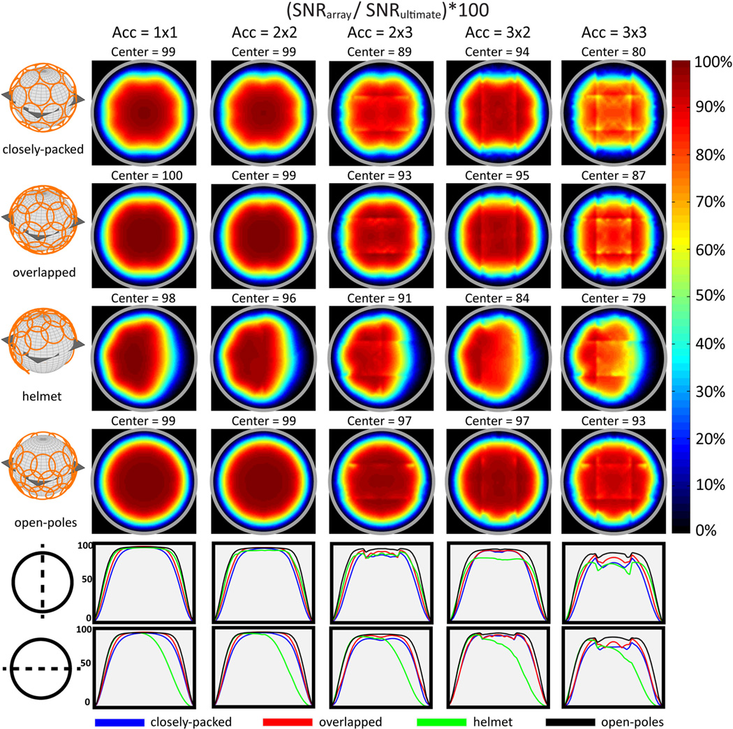
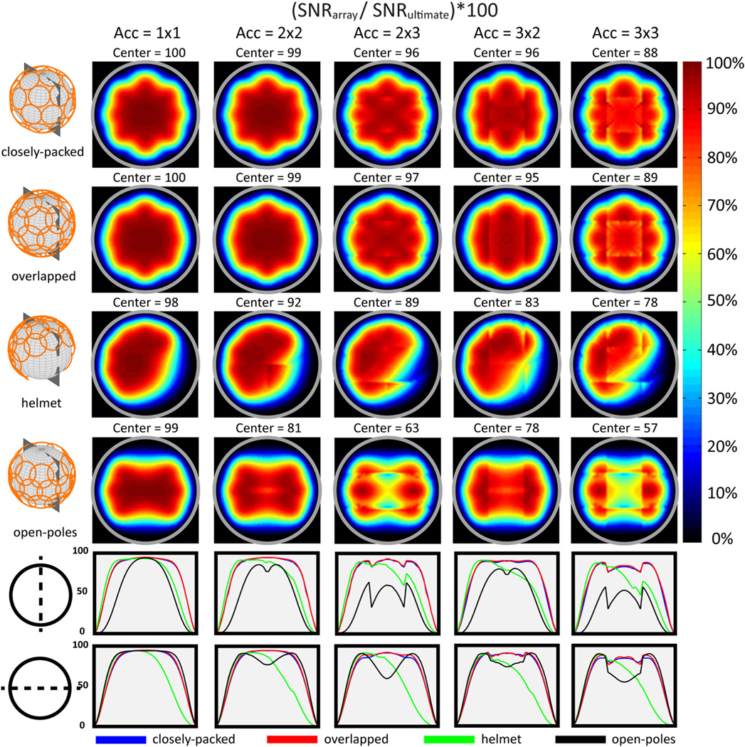
Figure 7 compares coil performance maps at 3 T for a transverse FOV using different acceleration factors for four 32-element array designs. The results show the impact of coil overlapping and packing strategy. The performance at the center of the object was equivalent for all four arrays for the fully-sampled and 2 × 2 accelerated cases. The performance of the “helmet” configuration, which might be suitable for in vivo brain imaging, was lower than for the other designs only when the acceleration factor was greater than two along the direction not surrounded by coils on both sides (i.e., 3 × 2 and 3 × 3 accelerations). The best overall performance was achieved by the “open-poles” array, which has all 32 elements concentrated around the transverse FOV. However, in the case of a sagittal FOV (Fig. 8), the performance of the “open-poles” array declined for increasing acceleration factors. This is due to the absence of array elements covering the top and bottom regions of the object, showing that even coils with their axis nearly aligned with the direction of the main magnetic field can contribute considerably to the SNR at the center when parallel imaging is used.
Figure 7. Coil performance maps of four 32-element array geometries for various acceleration factors at 3T, for a transverse plane in the center of a uniform sphere with 8.4cm radius.
Each voxel shows the SNR of the array normalized by the corresponding ultimate intrinsic SNR. Coil noise was included in the calculation of the SNR of the arrays. The gray circle indicates the surface of the sphere. The plots in the bottom row compare vertical and horizontal profiles for each map. The radius of the circular coil elements was optimized based on the geometrical arrangement: R = 3.0 cm for “closely-packed,” R = 3.9 cm for “overlapped,” R = 3.2 cm for “helmet,” R = 3.4 cm for “open-poles.” Although results are similar for acceleration factors 1 × 1 and 2 × 2, the geometry without coils around the north and south poles of the sphere (i.e., “open-poles”) yielded the highest performance for larger acceleration factors.
Figure 8. Coil performance maps of four 32-element array geometries for various acceleration factors at 3T, for a sagittal plane in the center of a uniform sphere (8.4 cm radius).
Coil noise was included in the calculation of the SNR of the arrays, which is shown for each voxel as a percentage of the corresponding ultimate intrinsic SNR. The gray circle indicates the surface of the sphere. The plots in the bottom row compare vertical and horizontal profiles for each map. The performance of the “helmet” array design is low in the front region not surrounded by coils, but it is comparable with that of the fully enclosing geometries at the center. The performance of the “open-poles” array design decreases significantly in the central region for this image plane orientation.
DISCUSSION
This work describes a comprehensive investigation of the performance of finite coil arrays with respect to the theoretical performance limits for an increasing number of elements and various experimental conditions. We used a simulation framework based on DGF to model different array geometries and perform rapid full-wave calculations of the corresponding EM fields inside a spherical object with uniform electrical properties. Array performance was assessed in terms of SNR and g-factor. The effect of conductor losses on the performance was evaluated. In this work, we have demonstrated that, when only sample noise is considered, SNR approaches its ultimate limit as the number of coil elements increases, for a voxel in the central and intermediate region of the object [Fig 2(a,b)]. For a voxel 0.4 cm below the surface of an 8.4 cm radius sphere, we found that array performance still increases with the number of elements, but approaches only 9% of the theoretical limit with 96 coils [Fig. 2(c)]. Although one could try to further increase the number of coil elements surrounding the sphere to approach the UISNR also in this case, that may result in a limitless and worthless endeavor, since the rate and extent at which the UISNR is approached for a particular geometry and field strength depends less on the number of elements than on its ability to mimic the ideal current patterns (17,18). Some of our prior work graphically demonstrated that at 1.5 T the ideal current patterns for UISNR at a voxel between the surface and the center of a homogenous sphere alternate between a distributed circular loop and a figure eight over time, showing that, in fact, an optimized standard surface quadrature arrangement would be more optimal than a large encircling array of loop coils (18). However, the same work showed that the ideal current patterns for the same voxel position are more complex above 7 T, suggesting that the same surface quadrature configuration would not be optimal at ultrahigh field and alternate coil configurations more closely resembling the ideal current patterns may be needed to approach the UISNR. Ideal current patterns are also useful to explain some of the results presented here. For a central voxel, the ideal current patterns form two rotating distributed loops over a range of field strengths (18); therefore, as shown in Figs. 2–5, increasing the number of coil elements in an encircling array improves SNR performance similarly for all field strengths. The improved array performance with increasing number of elements is likely due to the improved ability of the coil current patterns to mimic the loop-like shape and size of the ideal current patterns, in addition to the SNR advantage that a matched-filter combination provides with a multielement receive array (1). Similar behavior of array performance as a function of number of coils was shown in a conference abstract (16), using a different approach for the calculation of UISNR.
In general, for the case of only sample noise, array performance converged to the ultimate values more rapidly for low magnetic field strengths. Including coil noise in the SNR calculation resulted in lower overall array performance, especially at low to moderate magnetic field strengths. Array performance was almost unaffected by coil noise at higher field strengths (Figs. 3 and 4). These results are consistent with the fact that sample noise dominates at high field strength due to its larger scaling with frequency than coil noise (Appendix B). However, sample noise becomes dominant also at low field for large spheres [Fig. 3(f)], due to the large volume of conductive sample to which the larger sized coil elements required to surround the larger object are sensitive. Increasing the number of coil elements beyond 32 does not seem to have a significant impact on array performance in the center of the object, except for small sphere radii at 1.5 T [Fig. 3(d,e)], as the overall SNR improvement provided by larger arrays is counteracted by a corresponding increase in coil noise due to the larger amount of copper conductor. This is in agreement with published experimental results that showed that absolute coil performance with respect to the UISNR for a 32-element head array reached 85% in the center of a spherical phantom at 3 T (23).
Note that our simplified Johnson noise model underestimates total noise, as it neglects other noise sources, such as radiation losses, or losses due to capacitors and solder joints. Furthermore, our DGF framework assumes uniform current distribution within the coil conductors, whereas non-uniform cross-sectional current patterns, which are expected at high frequencies (25), could affect the balance of the results among different magnetic field strengths. Although more rigorous noise models could be used (26), an accurate prediction of coil performance would require building prototype coils matching the size of the loop elements for each simulated array to experimentally calibrate their actual resistance. In this work, we chose a simpler approach in exchange for rapid simulations that allowed us to investigate the effect of a large number of parameters on the SNR. Note that, although our predicted array performance is likely higher than what would be measured, we do not expect a large deviation (23).
Array performance decreases when parallel imaging with 4-fold linear acceleration is used, especially at low magnetic field strength, and a larger number of coils are needed to approach the ultimate limits (Fig. 5). Increase in array efficiency (i.e., lower g-factor) with higher number of coil elements for an acceleration rate of 4 (Fig. 6) is in accordance with the conclusions in Wiesinger’s doctoral thesis (15). The fact that the g-factor approaches its ultimate value as the number of coil elements is increased confirms that parallel imaging benefits from larger arrays of smaller loops with localized coil sensitivities. Our results suggest that there is an additional advantage associated with high magnetic field strengths, as the convergence to the lowest possible g-factor is faster at 7 T than 1.5 T.
Weiger et al. (27) have shown that overlapping neighboring coils in a 6-element cardiac array can reduce parallel imaging performance. However, unpublished results, which are reported in a doctoral thesis (15), have shown that the SNR performance on a transverse FOV at 1.5T of an array of at least 32 closely packed loops around a uniform 10cm radius sphere is maximized if the coils are overlapped, both for no acceleration and for 4-fold linear acceleration. In agreement with these results, we found in this work that for a 32-element array, overlapping coils yielded the highest SNR in a transverse plane of an 8.4 cm radius uniform sphere, for various acceleration factors at 3T (Fig. 7). Note that array elements were perfectly decoupled in our simulation, which could be obtained in practice by, for example, using preamplifier decoupling, therefore, any change in performance was due to the different array geometry. Even though deeper EM field penetration of larger coil radii could partly explain the slightly better performance at the center in the unaccelerated case, the increasing advantage of the overlapped versus closely packed array with higher accelerations is counterintuitive, as overlapping of coil sensitivities is expected to worsen the g-factor. Array performance was not affected by coil overlapping in the case of a sagittal FOV (Fig. 8). Although the object is symmetric for any plane through its center, signal sensitivity, and therefore SNR, depends on the FOV and coil orientations with respect to the main magnetic field. Having array elements with their axis aligned along the direction of B0 is generally considered inefficient for MR reception. Our results for the “open-poles” array confirm such common assumptions for the case of an axial FOV (Fig. 7), but show that, if parallel imaging is used, surrounding the object as fully as possible with coils is critical to array performance for sagittal imaging planes. Due to symmetry, this result would also hold for the case of coronal planes. Note that in the center, where SNR is most critical, the performance of the “helmet” array is still considerably higher than for the “open-poles” array, even for large acceleration factors. In fact, for small accelerations it is comparable to that of the “closely-packed” and “overlapped” designs and for a 3 × 3 acceleration factor the difference is only ~10%. This result is significant because, while close packing of circular loops around a sphere is a convenient and valid approach to test array performance with respect to increasing number of coils, practical array geometries for head MRI applications would most likely have the shape of a helmet, with the loops rearranged to accommodate an open surface for the face and the neck.
Our work investigated the performance of loop coils. However, the UISNR calculations include both magnetic dipole and electric dipole contributions (i.e., divergence-free or closed-loop patterns and curl-free or nonclosed patterns, respectively). Thus, we cannot expect an array of loops to approach the UISNR closely in regions where the ideal current patterns have a significant electric-dipole component. In fact, for certain geometries electric dipoles can perform as well as or better than loops, especially at ultra-high field (28), and it has been shown in simulations and experiments that the SNR of an array combining loops and electric dipoles can be larger than the SNR of an array with the same number of elements but including only loops (29). One way of capturing all components of the optimal EM field distribution with an array of loops only is to use composite elements, each consisting of three independent current loops with their axes along three orthogonal spatial directions (30). Although this is possible in theory and was demonstrated in simulation (30), construction of an array of composite coil elements is a challenging task that has not been attempted in practice as of yet. A promising and relatively straightforward approach to improve array performance with respect to the UISNR, which was recently demonstrated in simulation, is to use a layer of high-permittivity materials between the array elements and the sample (31).
CONCLUSION
In this work, we used a rapid full-wave semianalytical method to predict array performance with respect to the UI limits. We provided physical insights to explain the observed trends with a set of key unifying principles. Using our DGF method (18), we cross-validated previous results for closely-packed arrays (15,16) and added new findings for alternative practical coil designs and different imaging planes. For low to moderate accelerations, array configurations with coils partially surrounding the object, as in an actual head array, have similar SNR at the center as close packing arrangements, if the number of elements is the same. For large acceleration factors, the performance of these designs can decrease considerably, if the limited coil coverage affects the encoding direction. Our DGF simulation tools enable investigation of array performance within a comprehensive theoretical framework and can provide practical guidance for coil designers.
ACKNOWLEDGMENTS
This work was supported in part by NIH R01 EB002568 and NIH R01 EB000447 and was performed under the rubric of the Center for Advanced Imaging Innovation and Research (CAI2R, www.cai2r.net), a NIBIB Biomedical Technology Resource Center (NIH P41 EB017183). The authors are grateful to Graham Wiggins for helpful discussion about coil noise at different magnetic field strengths.
APPENDIX A
MODE EXPANSION OF THE EM FIELD INSIDE A DIELECTRIC SPHERE
The DGF for a dielectric sphere can be constructed using the method of superposition (21):
| [A.1] |
where r′ is the location of the current source, a is the radius of the sphere and r is the position at which the EM field is calculated. As we want to calculate the EM field inside the sphere, we choose the second branch:
| [A.2] |
Here the complex wave numbers outside and inside the sphere are expressed as k0 and kin, respectively, Cl and Dl are found by applying Dirichlet boundary conditions (18), and M and N are spherical vector wave functions:
| [A.3] |
The superscript “+” in Eq. [A.2] indicates that the spherical Bessel function in A.3 is replaced by a spherical Hankel function of the first kind, with the same l. Substituting Eqs. [A.2] and [3] in Eq. [1], we can calculate the electric field inside the sphere as:
| [A.4] |
where ω is the RF frequency of operation and μ0 is the magnetic permeability in free space. Let us define the coefficients:
| [A.5] |
| [A.6] |
Applying the orthogonality relations of vector spherical harmonics (32) and substituting Eqs. [A.5] and [A.6], we can rewrite Eq. [A.4] as
| [A.7] |
From Maxwell’s equation and the symmetrical relationship between the vector wave functions (Eqs. [A.3]), the magnetic field can be calculated as:
| [A.8] |
Note that, although the expressions used here for EM fields are slightly different than those in Ref. (18), due to the use of a different notation and a regrouping of multiplicative factors, the relative scaling between the electric and the magnetic fields, and therefore the SNR, is the same.
APPENDIX B
DERIVATION OF UISNR
The UISNR for voxel position r0 can be calculated using Eq. [5], where the modes’ noise covariance matrix Ψmode can be derived from the expression of the noise equivalent resistance (18):
| [B.1] |
where Ψmode = TRLTT and RL is given by (18):
| [B.2] |
The matrix S in Eq. [5] contains the complex signal sensitivities of all modes at the target position r0 and all aliased positions, when parallel imaging is used:
| [B.3] |
Here R is the acceleration factor and Lmode = 2(lmax + 1)2 is the total number of modes corresponding to the expansion order lmax, which is chosen to ensure convergence of calculations. The elements of S can be derived using the principle of reciprocity (33), which allows the calculation of receive sensitivity as (18):
| [B.4] |
OPTIMAL SNR FOR FINITE ARRAYS
The optimal SNR for an array of circular loops can be calculated with Eq. [5], after applying the combination weights to the modes’ sensitivity and noise covariance matrices as in Eq. [7]. By definition, the only type of noise contributing to UISNR is sample noise. In the case of finite arrays, the DGF formalism allows the addition of coil noise contributions in a straightforward manner, by substituting Ψ̃mode = Ψmode + RA in Eq. [7], where RA accounts for resistive power losses in the coil conductors and is defined in Ref. (18).
REFERENCES
- 1.Roemer PB, Edelstein WA, Hayes CE, Souza SP, Mueller OM. The NMR phased array. Magn Reson Med. 1990;16:192–225. doi: 10.1002/mrm.1910160203. [DOI] [PubMed] [Google Scholar]
- 2.Sodickson DK, Manning WJ. Simultaneous acquisition of spatial harmonics (SMASH): fast imaging with radiofrequency coil arrays. Magn Reson Med. 1997;38:591–603. doi: 10.1002/mrm.1910380414. [DOI] [PubMed] [Google Scholar]
- 3.Pruessmann KP, Weiger M, Scheidegger MB, Boesiger P. SENSE: sensitivity encoding for fast MRI. Magn Reson Med. 1999;42:952–962. [PubMed] [Google Scholar]
- 4.Griswold MA, Jakob PM, Heidemann RM, Nittka M, Jellus V, Wang J, et al. Generalized autocalibrating partially parallel acquisitions (GRAPPA) Magn Reson Med. 2002;47:1202–1210. doi: 10.1002/mrm.10171. [DOI] [PubMed] [Google Scholar]
- 5.Schmitt M, Potthast A, Sosnovik DE, Polimeni JR, Wiggins GC, Triantafyllou C, et al. A 128-channel receive-only cardiac coil for highly accelerated cardiac MRI at 3 Tesla. Magn Reson Med. 2008;59:1431–1439. doi: 10.1002/mrm.21598. [DOI] [PMC free article] [PubMed] [Google Scholar]
- 6.Ibrahim TS, Lee R, Baertlein BA, Kangarlu A, Robitaille PML. Application of finite difference time domain method for the design of birdcage RF head coils using multi-port excitations. Magn Reson Imaging. 2000;18:733–742. doi: 10.1016/s0730-725x(00)00143-0. [DOI] [PubMed] [Google Scholar]
- 7.Collins CM, Smith MB. Signal-to-noise ratio and absorbed power as functions of main magnetic field strength, and definition of “90 degrees” RF pulse for the head in the birdcage coil. Magn Reson Med. 2001;45:684–691. doi: 10.1002/mrm.1091. [DOI] [PubMed] [Google Scholar]
- 8.Collins CM, Li S, Smith MB. SAR and B1 field distributions in a heterogeneous human head model within a birdcage coil. Specific energy absorption rate. Magn Reson Med. 1998;40:847–856. doi: 10.1002/mrm.1910400610. [DOI] [PubMed] [Google Scholar]
- 9.Han Y, Wright SM. Analysis of RF penetration effects in MRI using finite-difference-time-domain method. Proc 12th Ann Sci Mtg Soc Magn Reson Med. 1993:1327. [Google Scholar]
- 10.Collins CM. Numerical field calculations considering the human subject for engineering and safety assurance in MRI. NMR Biomed. 2009;22:919–926. doi: 10.1002/nbm.1251. [DOI] [PMC free article] [PubMed] [Google Scholar]
- 11.Ocali O, Atalar E. Ultimate intrinsic signal-tonoise ratio in MRI. Magn Reson Med. 1998;39:462–473. doi: 10.1002/mrm.1910390317. [DOI] [PubMed] [Google Scholar]
- 12.Schnell W, Renz W, Vester M, Ermert H. Ultimate signal-to-noise-ratio of surface and body antennas for magnetic resonance imaging. IEEE Trans Antennas Propag. 2000;48:418–428. [Google Scholar]
- 13.Ohliger MA, Grant AK, Sodickson DK. Ultimate intrinsic signal-to-noise ratio for parallel MRI: electromagnetic field considerations. Magn Reson Med. 2003;50:1018–1030. doi: 10.1002/mrm.10597. [DOI] [PubMed] [Google Scholar]
- 14.Wiesinger F, Boesiger P, Pruessmann KP. Electrodynamics and ultimate SNR in parallel MR imaging. Magn Reson Med. 2004;52:376–390. doi: 10.1002/mrm.20183. [DOI] [PubMed] [Google Scholar]
- 15.Wiesinger F. Ph.D. Theses. Swiss Federal Institute of Technology Zurich; 2005. Parallel Magnetic Resonance Imaging: Potential and Limitations at High Fields. [Google Scholar]
- 16.Wiesinger F, Zanche ND, Pruessman KP. Approaching ultimate SNR with finite coil arrays. Proc 13th Ann Sci Mtg Int Soc Magn Reson Med. 2005:672. [Google Scholar]
- 17.Lattanzi R, Grant AK, Sodickson DK. Approaching ultimate SNR and ideal current patterns with finite surface coil arrays on a dielectric cylinder. Proc Int Soc Magn Reson Med. 2008;16:1074. [Google Scholar]
- 18.Lattanzi R, Sodickson DK. Ideal current patterns yielding optimal signal-to-noise ratio and specific absorption rate in magnetic resonance imaging: computational methods and physical insights. Magn Reson Med. 2012;68:286–304. doi: 10.1002/mrm.23198. [DOI] [PMC free article] [PubMed] [Google Scholar]
- 19.Duan Q, Sodickson DK, Lattanzi R, Zhang B, Wiggins GC. Optimizing 7T spine array design through offsetting of transmit and receive elements and quadrature excitations. Proc 18th Ann Sci Mtg Int Soc Magn Reson Med. 2010:51. [Google Scholar]
- 20.Lattanzi R. Massachusetts Institute of Technology: Ph.D. Theses. Harvard University—MIT Division of Health Sciences and Technology; 2008. Coil performance evaluation based on electrodynamics : tools for hardware design and validation in magnetic resonance imaging. [Google Scholar]
- 21.Tai CT. Dyadic Green Functions in Electromagnetic Theory: Institute of Electrical and Electronics Engineers. New Jersey: Piscataway; 1994. [Google Scholar]
- 22.Wiggins GC, Polimeni JR, Potthast A, Schmitt M, Alagappan V, Wald LL. 96-Channel receive-only head coil for 3 Tesla: design optimization and evaluation. Magn Reson Med. 2009;62:754–762. doi: 10.1002/mrm.22028. [DOI] [PMC free article] [PubMed] [Google Scholar]
- 23.Lattanzi R, Grant AK, Polimeni JR, Ohliger MA, Wiggins GC, Wald LL, et al. Performance evaluation of a 32-element head array with respect to the ultimate intrinsic SNR. NMR Biomed. 2009;23:142–151. doi: 10.1002/nbm.1435. [DOI] [PMC free article] [PubMed] [Google Scholar]
- 24.Pruessmann KP, Weiger M, Scheidegger MB, Boesiger P. SENSE: sensitivity encoding for fast MRI. Magn Reson Med. 1999;42:952–962. [PubMed] [Google Scholar]
- 25.Rautio JC. An investigation of microstrip conductor loss. IEEE Microwave Mag. 2000;1:60–67. [Google Scholar]
- 26.Duan Q, Sodickson DK, Zhang B, Wiggins G. A comprehensive coil resistance composition model for high field. Proc 12th Ann Sci Mtg Int Soc Magn Reson Med. 2010:3858. [Google Scholar]
- 27.Weiger M, Pruessmann KP, Leussler C, Roschmann P, Boesiger P. Specific coil design for SENSE: a six-element cardiac array. Magn Reson Med. 2001;45:495–504. doi: 10.1002/1522-2594(200103)45:3<495::aid-mrm1065>3.0.co;2-v. [DOI] [PubMed] [Google Scholar]
- 28.Raaijmakers AJE, Ipek O, Klomp DWJ, Possanzini C, Harvey PR, Lagendijk JJW, et al. Design of a radiative surface coil array element at 7 T: the single-side adapted dipole antenna. Magn Reson Med. 2011;66:1488–1497. doi: 10.1002/mrm.22886. [DOI] [PubMed] [Google Scholar]
- 29.Wiggins GC, Zhang B, Cloos M, Lattanzi R, Chen G, Lakshmanan K, et al. Mixing loops and electric dipole antennas for increased sensitivity at 7 Tesla. Proc Int Soc Magn Reson Med. 2013;21:2737. [Google Scholar]
- 30.Wang ZJ. Towards a complete coil array. Magn Reson Imaging. 2008;26:1310–1315. doi: 10.1016/j.mri.2008.02.002. [DOI] [PubMed] [Google Scholar]
- 31.Lattanzi R, Vaidya MV, Carluccio G, Sodickson DK, Collins CM. Effects of high-permittivity materials on absolute RF coil performance as a function of B0 and object size. Proc Int Soc Magn Reson Med. 2014;22:4818. [Google Scholar]
- 32.Jackson . Classical Electrodynamics. 3rd Edition. New York: Wiley; 1999. [Google Scholar]
- 33.Hoult DI. The principle of reciprocity in signal strength calculations—A mathematical guide. Concepts Magn Reson. 2000;12:173–187. [Google Scholar]


