Abstract
Purpose
Elongated conductors, such as pacemaker leads, neurostimulator leads, and conductive guidewires used for interventional procedures, can couple to the MRI radiofrequency (RF) transmit field, potentially causing dangerous tissue heating. The purpose of this work is to demonstrate the feasibility of using parallel transmit to control induced RF currents in elongated conductors, thereby reducing the RF heating hazard.
Methods
Phantom experiments were performed on a four-channel parallel transmit system at 1.5T. Parallel transmit “null mode” excitations that induce minimal wire current were designed using coupling measurements derived from axial B1+ maps. The resulting current reduction performance was evaluated with B1+ maps, current sensor measurements, and fluoroptic temperature probe measurements.
Results
Null mode excitations reduced the maximum coupling mode current by factors ranging from 2–80. For the straight wire experiment, a current null imposed at a single wire location was sufficient to reduce tip heating below detectable levels. For longer insertion lengths and a curved geometry, imposing current nulls at two wire locations resulted in more distributed current reduction along the wire length.
Conclusion
Parallel transmit can be used to create excitations that induce minimal RF current in elongated conductors, thereby decreasing the RF heating risk, while still allowing visualization of the surrounding volume.
Keywords: RF safety, RF heating, parallel transmit, transmit arrays, implanted devices, MR safety
Introduction
Elongated conductors, such as neurostimulator leads, cardiac pacemaker leads, and conductive guidewires used for interventional procedures, present a heating risk in MRI (1). The radiofrequency (RF) transmit field used in MRI can induce currents in these conductors, potentially causing dangerous heating of surrounding tissues. Phantom studies have shown wire tip temperature increases exceeding 48°C (2–4), and clinical scans have resulted in serious RF-induced patient injury (5,6). This RF heating hazard is one of the reasons that patients with implanted medical devices are routinely excluded from receiving MRI scans.
Most efforts to solve this RF safety problem have focused on modifying the material composition or electromagnetic properties of the implanted devices to render them inherently safe for MRI. Examples include inserting cable traps, transformers, or baluns in long conductors to present high impedance to RF currents (7,8), inserting coiled or “billabong” windings to add inductive reactance (9), using diode circuitry to detune the device during transmit (10), increasing lead tip contact area (11), or replacing conductive wires with fiber-optic connections (12). In fact, many medical device manufacturers now offer “MR-conditional” pacemakers and neurostimulators. However, challenges still remain for patients with standard device models, and the lack of MR-safe guidewires and catheters is an obstacle for interventional MRI (13).
In this work, we explore a different approach to the RF heating problem. Instead of modifying implanted devices for the MR-environment, our goal is to make the MR-environment itself safer for existing devices. The approach uses the “degrees of freedom” (14) inherent in an array of independently-controllable transmit surface coils to design excitations that induce minimal RF current in implanted conductors. Previous systems dedicated to interventional MRI have used surface coil transmit (15). Recent simulations have shown the feasibility of using an eight-channel system at 3T to control heating near deep brain stimulator electrodes (16). Past work by Graesslin et al. detected unsafe interactions using pick-up-coil signals from each element of an eight-coil transmit array and modified the scan to reduce RF heating by excluding any coils with unsafe device coupling levels (17). Ellenor et al. (18) demonstrated a similar result on a two-channel system using a low-power prescreen. Previous work has also demonstrated using a two-channel system at 3T to modify the electric field distribution to minimize implant heating (19,20) and a four-channel parallel transmit system at 1.5T to control induced currents in guidewires (21–24).
Here, we continue this work and show that with multiple transmit coils, it is possible to create parallel transmit excitations that induce minimal RF current in guidewires, thereby reducing the potential for RF heating, while still allowing visualization of the surrounding volume. We present B1+ maps, current sensor measurements, and fluoroptic temperature probe measurements to quantify the safety improvement. This method is general enough to be used in an interventional procedure, where the conductive structure is accessible, and for fully implanted devices, where there is no access to the conductive lead.
Theory
The heating hazard for conductive wires in MRI occurs because coupling with the RF transmit field transforms the wires into current-carrying antennas capable of focused power deposition at device-tissue interfaces, such as the wire tip (2,3). Nordbeck et al. showed that the induced RF current is an accurate predictor of the resulting RF heating, with tip heating increasing quadratically with tip RF current magnitude (4). Zanchi et al. showed a similar quadratic relation between tip heating and induced current (25). This is consistent with the fact that most device modifications for RF safety aim to suppress the flow of RF currents responsible for heating and/or reduce the effectiveness of the device as a current-carrying antenna (9,11). In this work, instead of modifying the device to inhibit current flow, our goal is to use parallel transmit to minimize the amount of RF current induced in the device, thereby reducing the potential for RF heating.
A complete theoretical characterization of the current induced in a conductor by the incident RF field involves solving Maxwell’s equations. As in classical antenna theory, the conductor can be treated as a scatterer of the incident electromagnetic field, and simulation methods such as finite difference time-domain or method of moments can estimate the induced current for various configurations and assumed field distributions.
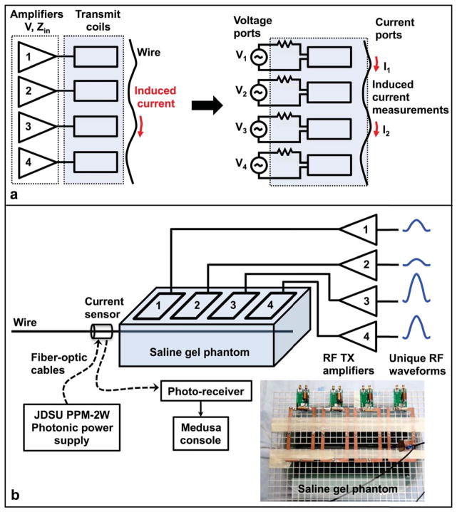
However, in the case of a linear medium such as biological tissue, where the conductivity, permittivity, and permeability are independent of the electric and magnetic fields, the source (MRI transmit coils) and scatterer (conductive lead or guidewire) system can be reduced to a multi-port network (26). Such a network can be fully characterized by the admittance parameters relating the input voltage supplied to the transmit coil RF amplifiers to the current induced at each observation point on the wire. For N transmit coils and M observation points, we have an N+M port network, as shown in Figure 1a for N = 4 and M = 2. The full admittance matrix need not be computed; a subset of only MN elements representing the coupling between each transmit coil and the current induced at each wire observation point suffices.
Figure 1.
(a): Multi-port network system representation for N = 4 coils and M = 2 wire current observation points. (b): Experiment setup showing the four-coil transmit array, arranged in a single row on top of saline gel phantom. The coils can also be arranged in a 2×2 block or volumetrically around the phantom. Each coil is connected to a dedicated RF power amplifier so that unique RF waveforms can be transmitted on all coils simultaneously to induce different current levels in the wire. A separate receive coil array (not shown) surrounds the phantom, and a photonically-powered, optically-coupled toroidal RF current sensor monitors induced currents. The sensor can be located outside the phantom as drawn, or submerged on the wire within the phantom, as shown in the photo inset.
For a fixed arrangement of transmit coils and conductor, the coupling between coil n of the transmit array and location m on the conductor can be represented by a complex coupling coefficient cmn. This coupling coefficient is a scalar multiple of the admittance parameter, where the scaling accounts for any system gains in the transmit chain before the amplifier input. The RF current induced in the conductor at location m is then a linear combination of these coupling coefficients, where the weights in the linear combination are the complex weights (magnitude and phase) applied to the RF transmit waveforms for each coil. By choosing different sets of transmit weights, different levels of current can be induced in the conductor.
Mathematically, for an N-coil transmit array system, M observation points on the conductor, and K distinct transmit weight vectors, we have:
| [1] |
where C is an M x N matrix of complex coupling coefficients, whose elements cmn represent the coupling between coil n = 1…N and location m = 1…M on the conductor; W is an N × K matrix of complex transmit weights, whose elements wnk represent the transmit weight to apply to the RF waveform on coil n to achieve coupling mode k = 1…K between the coil array and conductor; and I is an M x K matrix of induced currents, where each element Imk is the current induced at location m on the conductor by transmit mode k.
With this formulation, solving the RF coupling problem reduces to finding sets of transmit weights wnk that lie in the nullspace of the coupling matrix C, and thus result in zero current being induced in the conductor at the chosen location. We hypothesize that any linear combination of such “null modes” would also induce minimal current, and any imaging done within this restricted nullspace of transmit weights would be safer from RF heating. The dimension of the nullspace depends on the number of coils in the transmit array and the number of points on the conductor at which we wish to control the current. Increasing the number of transmit coils will increase the dimension of the nullspace, allowing more degrees of freedom to create excitations that induce minimal current. Restricting the current at more locations on the conductor will in general decrease the dimension of the nullspace.
Measuring Coupling Coefficients: Sensor-Based Method
The coupling coefficients cmn can be measured using a physical sensor or by image-based methods. When the conductive device is accessible, such as during an interventional procedure or for phantom studies, cmn can be found by transmitting a short RF pulse on coil n and recording the induced (complex) current measured by a sensor at location m on the wire. In this work, we use an optically-coupled photonically-powered toroidal RF current sensor (25,27) that measures the magnitude and phase of induced RF current on any conductive wire fed through its toroidal cavity. The sensor’s toroidal geometry allows current measurement without interrupting continuity or modifying the monitored wire, and the sensor can also be submerged within a phantom to map the current pattern along the wire length.
Measuring Coupling Coefficients: Image-Based Method
When the conductor is not accessible, cmn can be estimated from axial B1+ maps of the wire. Induced current on a wire adds a distinct disturbance to the background transmit coil field, (27–29). For wires parallel to B0, the total B1+ field becomes (from Eqs. 9–10 of (30)):
| [2] |
where Iw and ϕ are the magnitude and relative temporal phase, respectively, of the induced wire current, r is the radial distance from the wire center, θ is the spatial azimuthal polar coordinate, and μ is the magnetic permeability of the surrounding medium.
To synthesize complex B1+ data, we used Bloch-Siegert B1+ mapping (31) for |B1+|, and for phase data, we acquired an additional gradient-echo (GRE) image. This hybrid data structure is quite complex with noise and a sin(θ) component in |B1+| (29). Furthermore, coupling between the wire and receive coil perturbs the receive sensitivity, resulting in counteracting transmit/receive azimuthal phase twists (28,30). The post-processing of this hybrid data must extract and separate terms phase coherent with current from the background. Data were selected from an annulus centered on the wire. Defining a low-order polynomial f(x, y) approximating and anticipating azimuthal variations would tend to cancel over this annulus, we used a simplified approximation:
| [3] |
As will be seen, this simplification performed well under our experimental conditions. The image-based estimate of Iwejϕ is computed from Eq. 3 by least-squares fitting the axial B1+ map to a 1/r term to account for the wire current contribution and a polynomial f(x, y) = α1 + α2x + α3y + α4xy + α5x2 + α6y2 in spatial coordinates (x, y) with complex coefficients αi to account for the smoothly-varying transmit coil field:
| [4] |
The least-squares fit is performed over a ring-shaped region of B1+ map pixels centered on the wire and in close proximity to the wire (ring outer radius less than 1 cm). Each transmit coupling coefficient, cmn, is found by acquiring an axial B1+ map at location m on the wire when transmitting only with coil n, and computing Iwejϕ from the α0 coefficient determined from the least-squares fit of Eq. 4. Since the same receive-array sensitivity is used for all measurements, current nulling weights can be consistently computed. This method requires three images per coupling coefficient.
Computing Safe RF Excitations
Once the coupling coefficient matrix, C, has been found, the transmit weights for nulling current can be computed using a singular value decomposition (SVD) of C. The SVD of the M x N matrix C yields C = UΣV*, where U is an M x M unitary matrix, Σ is an M x N diagonal matrix of singular values, V is an N x N unitary matrix, and * denotes the conjugate transpose operation. The columns of V corresponding to the zero-valued singular values form a basis for the nullspace of C, while the column of V corresponding to the maximum singular value yields maximum amplification.
Thus choosing the transmit weight matrix, W, from Eq. 1 such that W = V is a convenient way to obtain transmit modes spanning the nullspace of C, as well as transmit modes designed to deliberately induce maximal wire current for comparison. Each column of W contains the transmit weights (magnitude and phase) of the RF waveforms for the N coils to achieve a specific level of induced wire current at the location of the coupling measurement. The columns of W corresponding to the nullspace of C are the “null modes” (i.e., imaging modes that should induce minimal wire current and reduced RF heating risk), while the columns corresponding to the largest singular values will induce higher current and present a greater heating hazard. The norm of each column of W obtained via SVD is unity. Consequently, the total forward transmit power for all modes is nominally equivalent, and any difference in induced wire current is from the choice of the relative magnitude and phase of the coil excitations, rather than a simplistic reduction of total transmitted power.
In the following experiments, we use the image-based and sensor-based methods to measure C. We then compute the transmit weight matrix, W, via SVD and evaluate the resulting current reduction performance with current sensor measurements, B1+ maps, and temperature measurements.
Methods
The experiment setup is shown in Figure 1b. All scans were performed on a GE Signa 1.5T scanner equipped with a four-channel parallel transmit system (32). An EP-catheter model consisting of insulated copper wire with 5 mm of exposed tip conductor (12 AWG wire, 2 mm conductor diameter, 0.5 mm insulation thickness, 130 cm total length, 39 cm immersed, wire oriented parallel to B0) was inserted in a saline gel phantom consisting of a 39 cm × 26 cm × 8 cm tub filled with a mixture of distilled water, 8 g/L Polyacrylic Acid (Aldrich Chemical) and 0.7 g/L sodium chloride (33) to achieve a conductivity of approximately 0.5 S/m and relative permittivity of approximately 88 (DAK, Speag) to have properties comparable to human tissue. The phantom was also doped with nickel chloride to reduce the T1 to approximately 300 ms to enable faster imaging. Four 15 cm × 8 cm transmit surface coils were arranged across the top of the phantom, configured either in a single row or a symmetric 2×2 block, and the phantom and transmit coils were surrounded by a separate receive coil array. A photonically-powered optically-coupled toroidal RF current sensor (25,27) was located on the wire either directly outside the phantom or submerged inside the phantom, depending on the experiment, and the current sensor readings were recorded by the Medusa USB console (34). A look-up-table calibration was performed on each RF amplifier channel to correct for hardware nonlinearities.
Experiment 1: Null-mode Current Mapping
The matrix formulation presented in the Theory section imposes localized current nulls on the wire. To evaluate the wire current distribution at locations distal to the imposed null, the current sensor was used to map the spatial wire current pattern during null-mode transmit.
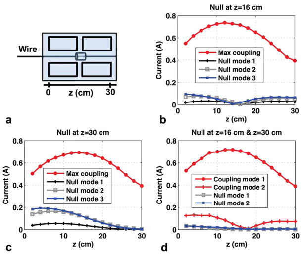
Figure 2a shows the experiment setup. The transmit coils were arranged in a 2×2 block on top of the phantom, with the current sensor positioned on the submerged portion of the wire. The 1×4 vector of complex coupling coefficients, C, was found using the sensor-based method by transmitting a 2-ms hard RF pulse on each transmit coil individually and recording the mean magnitude and phase of the current sensor measurement. The transmit weight matrix, W, was computed using the SVD of C, yielding three transmit modes (“null modes”) spanning the nullspace of C, as well as one transmit mode (“max coupling mode”) designed to deliberately induce maximal wire current for comparison.
Figure 2.
Experiment 1 results. (a): Setup showing 2×2 layout of transmit coils and submerged current sensor. (b): Current (mean magnitude in Amps-peak) for maximum coupling mode transmit and null-mode transmit when a single current null is imposed near the wire center at z = 16 cm. (c): Current for maximum coupling mode transmit and null-mode transmit when a single current null is imposed near the wire tip at z = 30 cm. (d): Current for maximum coupling mode transmit and null-mode transmit when current nulls are imposed at both z = 16 cm and z = 30 cm. Two-point nulling results in the loss of one degree of freedom in the nullspace, however the resulting nulling behavior is more distributed over the entire wire length.
The current control performance of the four transmit modes was then tested by transmitting hard RF pulses scaled by the complex weightings from the W matrix and recording the current sensor measurement as the sensor was moved in 2-cm increments from the base to the tip of the wire to map the resulting current distribution in each transmit mode and evaluate the nulling behavior at locations away from the imposed null. The experiment was performed for nulling locations at the wire center, near the wire tip, and for two-point nulling using the coupling data from both the center and tip. The two-point nulling experiment results in a 2×4 C matrix, and the SVD yields two coupling modes and two null modes, reflecting the tradeoff between the number of nulling locations and the dimension of the resulting nullspace.
Experiment 2: Image-Based Nulling, Symmetric Coil Arrangement
To demonstrate nulling using the image-based method, the transmit coils were arranged in a 2×2 block on top of the phantom, with the current sensor submerged in the phantom on the wire. Individual-coil axial Bloch-Siegert B1+ maps (31) (TR/TE = 50/6 ms, matrix size = 256 × 256, field of view (FOV) = 20 cm, 1-cm slice thickness, 2-ms slice-select pulse followed by 6-ms Fermi pulse with 3 kHz off resonance) were acquired at a single slice location near the current sensor (approximately 3 cm away from the sensor).
The 1×4 vector of complex coupling coefficients, C, was found by fitting the four individual-channel B1+ maps to Eq. 4, as described in the Theory section. The W matrix of transmit weights was computed via SVD as in Experiment 1, yielding three transmit modes spanning the nullspace of C and one transmit mode designed to deliberately induce maximal wire current for comparison.
The current control performance of these four transmit modes was then tested by acquiring B1+ maps when transmitting with RF waveforms scaled by the complex weightings from the columns of the W matrix. Axial B1+ maps were acquired to evaluate the current nulling performance at the location of the coupling measurements, and coronal B1+ maps (FOV = 40 cm) were acquired to determine if the nulling was distributed along the wire length. Current sensor measurements during the scans monitored induced RF current levels for all transmit modes tested.
Experiment 3: Image-Based & Sensor-Based Nulling, Linear Coil Arrangement
To test if the nulling procedure extends to different coil configurations, Experiment 2 was repeated with the transmit coils arranged in a single row on top of the phantom. Transmit weights were computed using image-based coupling measurements and SVD, and B1+ maps and submerged current sensor measurements verified the current nulling performance. Transmit weights were also computed using coupling coefficients measured with the submerged current sensor, and coronal B1+ maps determined if the nulling was distributed along the wire length.
To evaluate the potential loss in excitation ability when restricting excitations to the null modes, we performed a principal component analysis of the transmit modes (35,36). The SVD of the axial B1+ map data was computed using all transmit modes (coupling mode and null modes), and then using only the null modes. The excitation corresponding to the maximum singular value of the null mode data was then used to demonstrate that linear combinations of null modes also induce minimal current and can provide sufficient excitation to visualize the wire and the surrounding medium.
Experiment 4: Image-Based Nulling, Curved Wire
To test the nulling capabilities on a curved wire geometry, Experiment 2 was repeated for a longer immersion length and curved wire configuration. Insulated wire (18 AWG copper wire, 1.1 mm conductor diameter, 0.3 mm insulation thickness, 5 mm tip conductor exposed) of total length 130 cm was placed in the phantom in a curved configuration with 74 cm immersed. The transmit coils were arranged in a 2×2 block on top of the phantom, and the current sensor was located on the wire outside the phantom. Transmit weights for current nulling and maximal current were determined using image-based coupling measurements and SVD, as in Experiments 2–3, and the resulting nulling performance was evaluated with B1+ maps and current sensor measurements. Both single-point and two-point nulling were performed.
Experiment 5: Heating Test
To verify that the reduction of induced RF current results in the reduction of RF heating, fluoroptic temperature probe measurements were collected during null-mode transmit and maximal mode transmit. The transmit coils were arranged in a 2×2 block on top of the phantom, and fluoroptic temperature probes (Luxtron, m3300) were positioned at three locations on the wire in the phantom: (i) the wire tip, (ii) the wire base near the entry point into the phantom, and (iii) the background phantom medium away from the wire. The tip and base locations were chosen because they represent locations of maximum heating potential. The current sensor was located approximately 11 cm from the wire tip. The W matrix containing a maximum coupling mode and three null modes was computed from coupling measurements collected using the submerged current sensor, as in Experiment 1. The heating behavior of the four transmit modes was then tested by repeatedly applying scaled RF waveforms from the Bloch-Siegert B1+ mapping sequence (TR = 20 ms, repeated for six minutes of heating per transmit mode). Temperature measurements were also collected to determine if the acquisition of the individual-channel Bloch-Siegert B1+ maps required for the image-based coupling coefficient measurement causes heating (TR = 50 ms, 256 repetitions, three images per coil channel). Note that as in all prior experiments, the total forward power delivered to all coils was the same for individual-coil transmit, maximum coupling mode transmit, and null-mode transmit.
Results
Experiment 1: Null-mode Current Mapping
Figure 2b shows more than 50-fold reduction (727 mA vs. 14 mA) of induced wire current at the location of the coupling measurement when transmitting with any of the three null modes compared to the maximal coupling mode. The induced RF current magnitude increases away from the null location to 95 mA at the wire base, which is still a six-fold reduction in current compared to the maximal coupling mode.
Figure 2c shows the results of imposing the current null near the wire tip. Tip current is reduced by a factor of 78 (393 mA vs. 5 mA) with null-mode transmit, but the nulling performance degrades near the wire base to a 2.7-fold reduction in current.
Figure 2d shows that imposing nulls at two points on the wire results in a more distributed current null along the wire, at the cost of decreasing the nullspace dimension by one. Transmit with either of the two remaining null modes yields more than 16-fold reduction in induced current at all wire locations compared to the maximal coupling mode.
Experiment 2: Image-Based Nulling, Symmetric Coil Arrangement
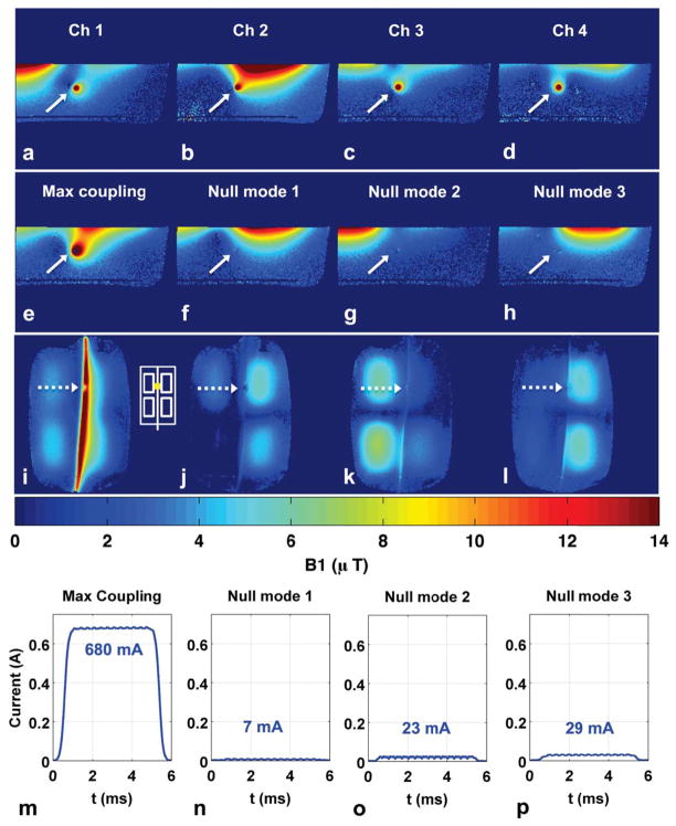
Figure 3 shows significant disturbance of the background B1+ field near the wire for individual coil transmit (Fig. 3a–d, arrows) and maximum coupling mode transmit (Fig. 3e, i), which indicates that RF current is being induced in the wire. The B1+ maps for null-mode transmit (Fig. 3 f–h) show almost no disturbance of the background field at the wire location, indicating little induced RF current. The current sensor measurements and image-based current estimates (Supporting Table S1) validate this; null-mode transmit results in a more than 20-fold reduction (680 mA vs. 29 mA) of induced wire current at the sensor location. The coronal B1+ maps (Fig. 3 j–l) show only minor disturbance of the background coil field near the wire, indicating that the current reduction in null-mode transmit is distributed along the entire wire length.
Figure 3.
Experiment 2 results. (a–d): Individual coil axial B1+ maps used to compute the coupling coefficients and W matrix containing a “maximum coupling” mode designed to induce maximum current and three “null modes” designed to induce minimal current. (e–h): Axial B1+ maps when transmitting with maximum coupling mode and three null modes. Solid arrows denote wire location. (i–l): Coronal B1+ maps when transmitting with maximum coupling mode and three null modes. Dotted arrows mark location of submerged current sensor and approximate slice location for axial B1+ maps in (a–h). White inset shows transmit coil layout and current sensor position. (m–p): Current sensor magnitude measurements during B1+ map acquisition for the four transmit modes. Null-mode transmit results in more than 20-fold reduction of induced wire current (680 mA vs. 29 mA) at the sensor location.
Experiment 3: Image-Based & Sensor-Based Nulling, Linear Coil Arrangement
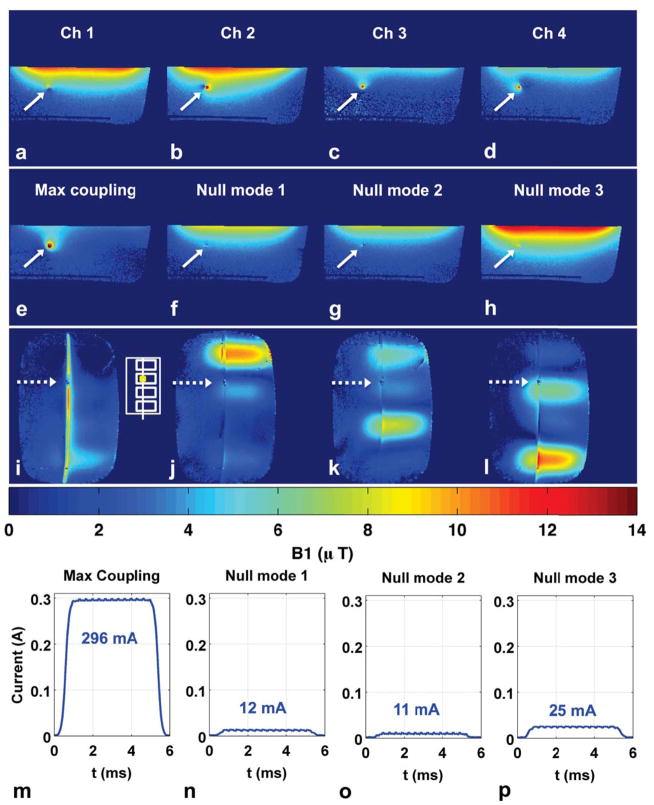
Figure 4 shows results similar to Figure 3, indicating that the nulling procedure extends to non-symmetric transmit coil configurations. Significant disturbance of the background B1+ field is seen for individual coil (Fig. 4a–d) and maximal coupling mode transmit (Fig. 4e, i), while very little disturbance is seen for null-mode transmit (Fig. 4f–h, j–l). The current sensor measurements are consistent with the B1+ maps (Supporting Table S1), showing 12-fold reduction in induced current for null-mode transmit (296 mA vs. 25 mA). The coronal B1+ maps indicate current reduction along much of the wire length, but the brightening near the wire tip in null mode 1 (Fig. 4j) and wire base in null mode 3 (Fig. 4l) indicates increased current at these locations. This behavior is consistent with the current patterns in Figure 2, where current can increase at locations away from the nulling point.
Figure 4.
Experiment 3 results. (a–d): Individual coil axial B1+ maps used to compute the coupling coefficients and W matrix containing a “maximum coupling” mode designed to induce maximum current and three “null modes” designed to induce minimal current. (e–h): Axial B1+ maps when transmitting with maximum coupling mode and three null modes. Solid arrows denote wire location. (i–l): Coronal B1+ maps when transmitting with maximum coupling mode and three null modes. Dotted arrows mark location of submerged current sensor and approximate slice location for axial B1+ maps in (a–h). White inset shows transmit coil layout and current sensor position. (m–p): Current sensor magnitude measurements during B1+ map acquisition for the four transmit modes. Null-mode transmit results in more than 11-fold reduction of induced wire current (296 mA vs. 25 mA) at the sensor location.
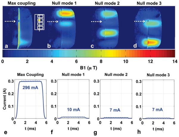
The sensor-based nulling results in Figure 5 are very similar to the image-based nulling results in Figure 4, with maximal coupling mode current being reduced from 296 mA to 10 mA. The localized nulling performance measured by the sensor is slightly improved (29-fold reduction vs. 12-fold) because of the exact co-location between the sensor-based coupling measurement and the subsequent evaluation of nulling performance with the sensor at that location (see also Sup. Table S1).
Figure 5.
Experiment 3 results: sensor-based nulling. (a–d): Coronal B1+ maps when transmitting with maximum coupling mode and three null modes derived from coupling coefficients measured using the current sensor. Dotted arrows mark location of submerged current sensor. White inset shows transmit coil layout and current sensor position. (e–h): Current sensor magnitude measurements during B1+ map acquisition for the four transmit modes. Null-mode transmit results in more than 29-fold reduction of induced wire current (296 mA vs. 10 mA) at the sensor location.
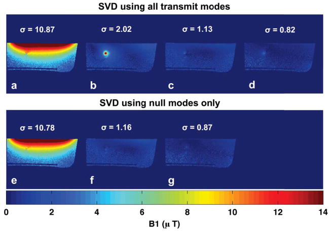
Figure 6 shows that very little excitation energy is lost by restricting excitations to lie in the nullspace of C; the maximum singular values (Fig. 6a, e) differ by less than 1% whether the maximum coupling mode is included or not. This indicates that the attainable image quality is predominantly limited by the inherent inhomogeneity of a given arrangement of surface coils, rather than any losses due to restricting excitations to lie in the coupling nullspace.
Figure 6.
Experiment 3 results. (a–d): SVD of B1+ maps in Figure 4 (e–h) shows basis for possible excitations when using all transmit modes (max coupling and nullmodes). (e–g): SVD of B1+ maps in Figure 4 (f–h) shows basis for possible excitations when using only null mode transmit. The small difference between maximum singular values (10.87 vs. 10.78) indicates that little excitation capability is lost in restricting excitations to linear combinations of nullmodes.
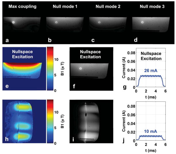
The axial GRE magnitude images in Figure 7b–d show that null-mode transmit still results in substantial background excitation for imaging. Note that even during null mode transmit, the wire is still visible as a bright artifact in the GRE magnitude images, due to coupling with the receive coil. Figure 7e–g show the results of imaging with a new excitation designed within this imaging nullspace. This new excitation is the linear combination of null modes shown in Figure 6e, and provides more excitation depth than any of the individual null modes, while inducing only 26 mA of current at the sensor location. Figure 7h–j show a coronal excitation in the nullspace that allows visualization of the wire’s entire extent, while inducing only 10 mA.
Figure 7.
Experiment 3 results. (a–d): Axial GRE magnitude images corresponding to B1+ maps in Figure 4 (e–h). The wire remains visible in null-mode transmit due to coupling with the receive coil array. (e–g): Axial B1+ map, GRE magnitude image, and current sensor measurement for a new nullspace excitation of Figure 6e. (h–j): Coronal B1+ map, GRE magnitude image, and current sensor measurement for nullspace excitation designed to visualize the entire wire length.
Experiment 4: Image-Based Nulling, Curved Wire
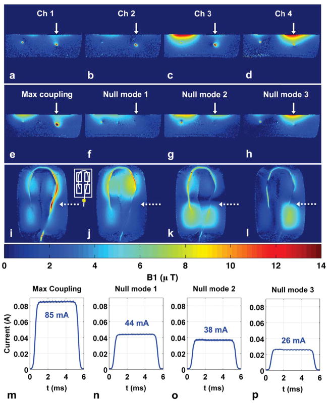
Figure 8 shows the results of performing single-point image-based nulling on a curved wire with longer immersion length. Current reduction is achieved locally at the chosen observation point on the wire (Fig. 8f–h, j–l, arrows), but induced current still exists at locations distal to this chosen point. This can be seen in the axial B1+ maps which show bright artifact at the curved-back wire location (Fig. 8f–h) and the coronal B1+ maps (Fig. 8j–l) that show substantial brightening at wire segments distal from the chosen nulling point. Note that the curved wire geometry requires three contiguous coronal slices to capture all wire portions. Figure 8i–l shows only the center slice, since this single slice clearly illustrates the degradation in nulling performance at locations distal to the imposed null. The current sensor readings at the wire location outside the phantom indicate a 1.9-fold reduction in current (85 mA to 44 mA) with null-mode transmit compared to maximal mode transmit.
Figure 8.
Experiment 4 results: single-point nulling. (a–d): Individual coil axial B1+ maps. Solid white arrows indicate wire location used to compute coupling coefficients. (e–h): Axial B1+ maps when transmitting with maximum coupling mode and three null modes. (i–l): Coronal B1+ maps when transmitting with maximum coupling mode and three null modes. Dotted arrows mark slice location for axial B1+ maps in (a–h) and location of imposed current null. White inset shows transmit coil layout and current sensor position. (m–p): Current sensor magnitude measurements during B1+ map acquisition for the four transmit modes. Null-mode transmit results in a 1.9-fold reduction of induced wire current (85 mA vs. 44 mA) at sensor location outside phantom.
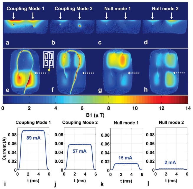
Figure 9 shows the results of performing two-point image-based nulling on the curved wire. The dimension of the nullspace decreases from three null modes to two, but the resulting current reduction in both remaining null modes is distributed along the entire wire length, as shown in the coronal B1+ maps (Fig. 9g, h). These B1+ maps are maximum-intensity projections of three contiguous coronal slices, to capture all of the curved wire geometry. The current sensor measurements at the wire location outside the phantom show a six-fold reduction in induced current with null-mode transmit (89 mA vs. 15 mA).
Figure 9.
Experiment 4 results: two-point nulling. (a–d): Axial B1+ maps when transmitting with two coupling modes and two null modes. White solid arrows mark the two wire locations used for coupling measurements and nulling. (e–h): Coronal B1+ maps (maximum intensity projection through three slices of data to capture all of wire) when transmitting with coupling and null modes. Dotted arrows mark slice location for axial B1+ maps in (a–d) and location of imposed current nulls. White inset shows transmit coil layout and current sensor position. (i–l): Current sensor magnitude measurements during B1+ map acquisition for the four transmit modes. Null-mode transmit results in a 6-fold reduction of induced wire current (89 mA vs. 15 mA) at the sensor location outside phantom.
Experiment 5: Heating Test
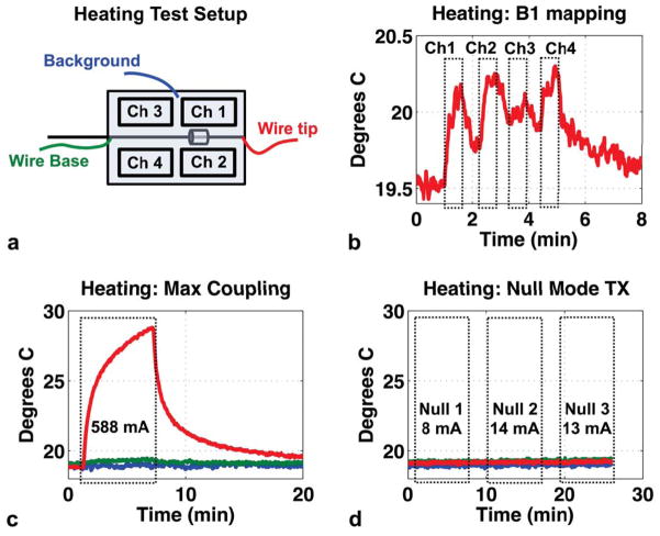
Figure 10b shows that the individual-channel B1+ maps needed for image-based coupling measurements can cause tip heating of approximately 1°C. The peak induced RF current levels measured by the sensor for individual-coil transmit were 323 mA, 287 mA, 248 mA and 287 mA, for channels 1–4, respectively.
Figure 10.
Experiment 5: Heating test. (a): Experiment setup showing transmit coils, submerged current sensor, and fluoroptic temperature probe placement at wire tip, base, and background phantom medium. (b): Tip heating during acquisition of individual-channel Bloch-Siegert B1+ maps (three images per channel, TR = 50 ms). (c): Temperature probe measurements when transmitting with the maximum coupling mode for six minutes of heating (588 mA-peak induced current). (d): Temperature probe measurements when transmitting for six minutes with each of the three null-modes. Wire tip temperature shown in red trace, wire base temperature in green, and background phantom temperature in blue.
Figure 10c–d show the heating results when transmitting with the maximum coupling mode and with the three null modes. Null-mode transmit decreases induced current by a factor of more than 40 (from 588 mA to 14 mA). Transmitting with the maximal coupling mode results in more than 10°C heating at the wire tip (Fig. 10c), while transmitting with any of the three null modes results in no measurable heating (Fig. 10d) at the wire base or tip, demonstrating that reduced wire current results in reduced heating.
Discussion
The results shown here demonstrate the feasibility of using parallel transmit to reduce RF heating near implanted conductors. This approach exploits the degrees of freedom inherent in a multi-coil array, using some degrees of freedom to minimize the wire currents that cause heating, while still leaving many possible safe “nullspace” excitations for imaging. Current reduction factors ranging from 2–80 were achieved between worst-case coupling modes and null-mode transmit. Since tip heating increases with the square of tip current magnitude (4), even a relatively modest factor-of-two reduction in induced current could substantially reduce the potential for RF heating.
While parallel transmit configurations are not standard on most MRI scanners, the possible gains in RF safety for patients with implanted devices could potentially justify the increased hardware complexity. This parallel transmit approach could be used in conjunction with device safety improvements to enhance the overall RF-safety of interventional MRI (27) and MRI for patients with permanently implanted medical devices. This approach could also be integrated with prescreening methods designed to detect potentially hazardous implants (18,30,37).
As shown in Figure 7, the nullspace excitations provide sufficient signal for imaging the volume surrounding the wire, and linear combinations of null modes can be used to improve image quality. The experiments here used a four-coil array in simple non-overlapped coil configurations on top of the phantom—a layout that is amenable to elongated catheter tracking at the cost of B1 homogeneity. Different coil arrangements, such as volumetric configurations and overlapping coils would likely create field patterns that are more amenable to homogeneous excitations. In principle, this method could be applied to a two-channel birdcage coil, in which case for non-centered wires, one coupled mode and one null mode would exist. The null mode should result in a linear-polarized zero E-field plane, similar to the results shown by Eryaman et al. (19,20). Increasing the number of coils in the transmit array would provide more degrees of freedom in the nullspace and additional flexibility to create useful nullspace excitations. Techniques such as magnitude least squares optimization (38) and spokes trajectories (16,39–41) could be used to create nullspace excitations with improved homogeneity.
Intuitively, the spatial rate of change of current is constrained by the propagation wavelength. The null placement relative to the tip should be “short” compared to a wavelength (< λ/10) to “pin down” the spatial current distribution. Insulated dipole theory (42) could predict wavelength for a given tissue loading and wire insulation thickness (here, λ ≈ 97 cm at 1.5T), however tip heating will ultimately also depend on the local contact impedance and current. In many cases, imposing a current null at a single point on the wire may be sufficient to substantially decrease the heating hazard. For example, the single-point nulling results in Figure 2b–c show significant reduction in induced wire current along the entire wire length, and the phantom heating study demonstrated substantial reduction in tip heating, with no associated increase in wire base heating, with just a single current null (Figure 10c, d) located near the wire tip. But for longer immersion lengths and more complicated wire geometries, two or more current nulls may be required to achieve adequate current reduction, as demonstrated in the curved wire experiment (Figure 9). Multiple nulls may also be necessary at higher magnetic field strengths, where the wavelength is shorter, and in the case of varying tissue types, where the loading along the wire may vary, and future work is needed to investigate this. Future work could also investigate the exact relationship between the spatial current pattern and the resulting heating along the wire. Furthermore, instead of asking for a true current null, the pulse design problem could instead be relaxed to ask for a reduction in current by a certain factor, which might result in more distributed nulling. Constraints on image homogeneity and minimum B1+ could also be included in such an optimization problem, so that the resulting null modes provide adequate image quality.
The B1+-map method to compute wire current and coupling coefficients was useful here for providing an unambiguous, quantitative evaluation of nulling performance. The resulting image-based current estimates are in agreement with the sensor measurements (Sup. Table S1). Future work could improve robustness and generalize the fit procedure for the azimuthal phase dependence as in (29), receive sensitivity effects, and especially, arbitrary wire orientation. However, B1+ mapping is time-consuming and may itself lead to heating (Figure 10b). An alternative approach to derive the coupling coefficients would be to avoid B1+ mapping and instead analyze image artifacts from low-flip (low SAR) GRE images, as in (28,43), or use a low-power impedance metric, as in (18).
Conclusion
Parallel transmit could be a promising way to improve the RF safety of MRI in the presence of elongated conductors, such as the leads of implanted medical devices and conductive guidewires used in interventional procedures. Phantom studies demonstrate that it is possible to reduce RF-induced current and heating, while still creating useful images of the surrounding volume. This method could be used in conjunction with improvements in device safety to provide additional RF safety assurance.
Supplementary Material
Current sensor measurements vs. image-based wire current estimates for Experiments 2 and 3.
Acknowledgments
This work is supported by NIH grants: R01EB008108, R33CA118276, P01CA159992, T32HL007846, and GE Healthcare.
References
- 1.Nyenhuis JA, Park S-M, Kamondetdacha R, Amjad A, Shellock FG, Rezai AR. MRI and implanted medical devices: basic interactions with an emphasis on heating. IEEE Trans Device Mater Reliab. 2005;5:467–480. doi: 10.1109/TDMR.2005.859033. [DOI] [Google Scholar]
- 2.Achenbach S, Moshage W, Diem B, Bieberle T, Schibgilla V, Bachmann K. Effects of magnetic resonance imaging on cardiac pacemakers and electrodes. Am Heart J. 1997;134:467–473. doi: 10.1016/s0002-8703(97)70083-8. [DOI] [PubMed] [Google Scholar]
- 3.Konings MK, Bartels LW, Smits HFM, Bakker CJG. Heating Around Intravascular Guidewires by Resonating RF Waves. J Magn Reson Imaging. 2000;12:79–85. doi: 10.1002/1522-2586(200007)12:1<79::AID-JMRI9>3.0.CO;2-T. [DOI] [PubMed] [Google Scholar]
- 4.Nordbeck P, Weiss I, Ehses P, et al. Measuring RF-induced currents inside implants: Impact of device configuration on MRI safety of cardiac pacemaker leads. Magn Reson Med. 2009;61:570–578. doi: 10.1002/mrm.21881. [DOI] [PubMed] [Google Scholar]
- 5.Rezai AR, Phillips M, Baker KB, Sharan AD, Nyenhuis J, Tkach J, Henderson J, Shellock FG. Neurostimulation system used for deep brain stimulation (DBS): MR safety issues and implications of failing to follow safety recommendations. Invest Radiol. 2004;39:300–303. doi: 10.1097/01.rli.0000124940.02340.ab. [DOI] [PubMed] [Google Scholar]
- 6.Henderson JM, Tkach J, Phillips M, Baker K, Shellock FG, Rezai AR. Permanent neurological deficit related to magnetic resonance imaging in a patient with implanted deep brain stimulation electrodes for Parkinson’s disease: case report. Neurosurgery. 2005;57:E1063. doi: 10.1227/01.neu.0000180810.16964.3e. discussion E1063. [DOI] [PubMed] [Google Scholar]
- 7.Ladd ME, Quick HH. Reduction of resonant RF heating in intravascular catheters using coaxial chokes. Magn Reson Med. 2000;43:615–619. doi: 10.1002/(sici)1522-2594(200004)43:4<615::aid-mrm19>3.0.co;2-b. [DOI] [PubMed] [Google Scholar]
- 8.Weiss S, Vernickel P, Schaeffter T, Schulz V, Gleich B. Transmission line for improved RF safety of interventional devices. Magn Reson Med. 2005;54:182–189. doi: 10.1002/mrm.20543. [DOI] [PubMed] [Google Scholar]
- 9.Bottomley PA, Kumar A, Edelstein WA, Allen JM, Karmarkar PV. Designing passive MRI-safe implantable conducting leads with electrodes. Med Phys. 2010;37:3828–3843. doi: 10.1118/1.3439590. [DOI] [PubMed] [Google Scholar]
- 10.Ocali O, Atalar E. Intravascular magnetic resonance imaging using a loopless catheter antenna. Magn Reson Med. 1997;37:112–118. doi: 10.1002/mrm.1910370116. [DOI] [PubMed] [Google Scholar]
- 11.Nordbeck P, Fidler F, Friedrich MT, et al. Reducing RF-related heating of cardiac pacemaker leads in MRI: Implementation and experimental verification of practical design changes. Magn Reson Med. 2012;68:1963–1972. doi: 10.1002/mrm.24197. [DOI] [PubMed] [Google Scholar]
- 12.Fandrey S, Weiss S, Müller J. A novel active MR probe using a miniaturized optical link for a 1.5-T MRI scanner. Magn Reson Med. 2012;67:148–155. doi: 10.1002/mrm.23002. [DOI] [PubMed] [Google Scholar]
- 13.Ratnayaka K, Faranesh AZ, Guttman MA, Kocaturk O, Saikus CE, Lederman RJ. Interventional cardiovascular magnetic resonance: still tantalizing. J Cardiovasc Magn Reson. 2008;10:62. doi: 10.1186/1532-429X-10-62. [DOI] [PMC free article] [PubMed] [Google Scholar]
- 14.Zhu Y. Parallel excitation with an array of transmit coils. Magn Reson Med. 2004;51:775–784. doi: 10.1002/mrm.20011. [DOI] [PubMed] [Google Scholar]
- 15.Schenck JF, Jolesz FA, Roemer PB, Cline HE, Lorensen WE, Kikinis R, Silverman SG, Hardy CJ, Barber WD, Laskaris ET. Superconducting open-configuration MR imaging system for image-guided therapy. Radiology. 1995;195:805–814. doi: 10.1148/radiology.195.3.7754014. [DOI] [PubMed] [Google Scholar]
- 16.Eryaman Y, Guerin B, Akgun C, et al. Parallel transmit pulse design for patients with deep brain stimulation implants. Magn Reson Med. 2014:n/a–n/a. doi: 10.1002/mrm.25324.. [DOI] [PMC free article] [PubMed] [Google Scholar]
- 17.Graesslin I, Weiss S, Hassani E, Nehrke K, Vernickel P, Krueger S. Detection and Countermeasures for RF Unsafe Conditions for MR-conditional Devices. Proceedings of the 19th Annual Meeting of ISMRM; Montreal, Quebec. 2011; p. 3771. [Google Scholar]
- 18.Ellenor CW, Stang PP, Etezadi-Amoli M, Pauly JM, Scott GC. Offline impedance measurements for detection and mitigation of dangerous implant interactions: An RF safety prescreen. Magn Reson Med. 2014:n/a–n/a. doi: 10.1002/mrm.25202.. [DOI] [PMC free article] [PubMed] [Google Scholar]
- 19.Eryaman Y, Akin B, Atalar E. Reduction of implant RF heating through modification of transmit coil electric field. Magn Reson Med. 2011;65:1305–1313. doi: 10.1002/mrm.22724. [DOI] [PubMed] [Google Scholar]
- 20.Eryaman Y, Turk EA, Oto C, Algin O, Atalar E. Reduction of the radiofrequency heating of metallic devices using a dual-drive birdcage coil. Magn Reson Med. 2013;69:845–852. doi: 10.1002/mrm.24316. [DOI] [PubMed] [Google Scholar]
- 21.Etezadi-Amoli M, Zanchi M, Stang P, Overall WR, Kerr AB, Pauly JM, Scott GC. Transmit Array Concepts for Improved MRI Safety in the Presence of Long Conductors. Proceedings of the 17th Annual Meeting of ISMRM; Honolulu, Hawaii. 2009; p. 4801. [Google Scholar]
- 22.Etezadi-Amoli M, Stang P, Zanchi M, Pauly JM, Scott GC, Kerr AB. Controlling Induced Currents in Guidewires Using Parallel Transmit. Proceedings of the 18th Annual Meeting of ISMRM; Stockholm, Sweden. 2010. p. 777. [Google Scholar]
- 23.Etezadi-Amoli M, Stang P, Pauly JM, Kerr AB, Scott GC. Parallel Transmit with Toroidal Transceiver for Enhanced Visualization and RF Safety. Proceedings of the 19th Annual Meeting of ISMRM; Montreal. 2011; p. 1749. [Google Scholar]
- 24.Gudino N, Sonmez M, Faranesh A, Lederman RJ, Balaban RS, Hansen MS, Griswold MA. Parallel Transmit Excitation at 1.5T Based on the Minimization of a Driving Function for Device Heating. Proceedings of the 21st Annual Meeting of ISMRM; Salt Lake City, Utah, USA. 2013; p. 287. [DOI] [PMC free article] [PubMed] [Google Scholar]
- 25.Zanchi MG, Venook R, Pauly JM, Scott GC. An optically coupled system for quantitative monitoring of MRI-induced RF currents into long conductors. IEEE Trans Med Imaging. 2010;29:169–178. doi: 10.1109/TMI.2009.2031558. [DOI] [PMC free article] [PubMed] [Google Scholar]
- 26.Harrington RF. Time-harmonic electromagnetic fields. New York: IEEE Press; 2001. [Google Scholar]
- 27.Etezadi-Amoli M, Stang P, Kerr A, Pauly J, Scott G. Interventional device visualization with toroidal transceiver and optically coupled current sensor for radiofrequency safety monitoring. Magn Reson Med. 2014:n/a–n/a. doi: 10.1002/mrm.25187.. [DOI] [PMC free article] [PubMed] [Google Scholar]
- 28.Venook RD, Overall WR, Shultz K, Conolly S, Pauly JM, Scott GC. Monitoring Induced Currents on Long Conductive Structures During MRI. Proceedings of the 16th Annual Meeting of ISMRM; Toronto, Ontario, Canada. 2008. p. 898. [Google Scholar]
- 29.Van den Bosch MR, Moerland MA, Lagendijk JJW, Bartels LW, van den Berg CAT. New method to monitor RF safety in MRI-guided interventions based on RF induced image artefacts. Med Phys. 2010;37:814–821. doi: 10.1118/1.3298006. [DOI] [PubMed] [Google Scholar]
- 30.Overall WR, Pauly JM, Stang PP, Scott GC. Ensuring Safety of Implanted Devices under MRI using Reversed RF Polarization. Magn Reson Med. 2010;64:823–833. doi: 10.1002/mrm.22468. [DOI] [PMC free article] [PubMed] [Google Scholar]
- 31.Sacolick LI, Wiesinger F, Hancu I, Vogel MW. B1 mapping by Bloch-Siegert shift. Magn Reson Med. 2010;63:1315–1322. doi: 10.1002/mrm.22357. [DOI] [PMC free article] [PubMed] [Google Scholar]
- 32.Stang P, Kerr AB, Pauly JM, Scott GC. An Extensible Transmit Array System using Vector Modulation and Measurement. Proceedings of the 16th Annual Meeting of ISMRM; Toronto, Ontario, Canada. 2008; p. 145. [Google Scholar]
- 33.Park SM, Nyenhuis JA, Smith CD, et al. Gelled versus nongelled phantom material for measurement of MRI-induced temperature increases with bioimplants. IEEE Trans Magn. 2003;39:3367–3371. doi: 10.1109/TMAG.2003.816259. [DOI] [Google Scholar]
- 34.Stang PP, Conolly SM, Santos JM, Pauly JM, Scott GC. Medusa: A Scalable MR Console Using USB. IEEE Trans Med Imaging. 2012;31:370–379. doi: 10.1109/TMI.2011.2169681. [DOI] [PMC free article] [PubMed] [Google Scholar]
- 35.Buehrer M, Pruessmann KP, Boesiger P, Kozerke S. Array compression for MRI with large coil arrays. Magn Reson Med. 2007;57:1131–1139. doi: 10.1002/mrm.21237. [DOI] [PubMed] [Google Scholar]
- 36.Huang F, Vijayakumar S, Li Y, Hertel S, Duensing GR. A software channel compression technique for faster reconstruction with many channels. Magn Reson Imaging. 2008;26:133–141. doi: 10.1016/j.mri.2007.04.010. [DOI] [PubMed] [Google Scholar]
- 37.Graesslin I, Krueger S, Vernickel P, Achtzehn J, Nehrke K, Weiss S. Detection of RF unsafe devices using a parallel transmission MR system. Magn Reson Med. 2013;70:1440–1449. doi: 10.1002/mrm.24558. [DOI] [PubMed] [Google Scholar]
- 38.Setsompop K, Wald Ll, Alagappan V, Gagoski Ba, Adalsteinsson E. Magnitude least squares optimization for parallel radio frequency excitation design demonstrated at 7 Tesla with eight channels. Magn Reson Med. 2008;59:908–915. doi: 10.1002/mrm.21513.. [DOI] [PMC free article] [PubMed] [Google Scholar]
- 39.Saekho S, Yip C, Noll DC, Boada FE, Stenger VA. Fast-kz three-dimensional tailored radiofrequency pulse for reduced B1 inhomogeneity. Magn Reson Med. 2006;55:719–724. doi: 10.1002/mrm.20840. [DOI] [PMC free article] [PubMed] [Google Scholar]
- 40.Setsompop K, Wald LL, Alagappan V, Gagoski B, Hebrank F, Fontius U, Schmitt F, Adalsteinsson E. Parallel RF transmission with eight channels at 3 Tesla. Magn Reson Med. 2006;56:1163–1171. doi: 10.1002/mrm.21042. [DOI] [PubMed] [Google Scholar]
- 41.Zhang Z, Yip C-Y, Grissom W, Noll DC, Boada FE, Stenger VA. Reduction of Transmitter B1 Inhomogeneity with Transmit SENSE Slice-Select Pulses. Magn Reson Med. 2007;57:842–847. doi: 10.1002/mrm.21221. [DOI] [PMC free article] [PubMed] [Google Scholar]
- 42.King RWP, Smith GS. Antennas in Matter: Fundamentals, Theory, and Applications. Cambridge: MIT Press; 1981. [Google Scholar]
- 43.Griffin GH, Anderson KJT, Celik H, Wright GA. Safely assessing radiofrequency heating potential of conductive devices using image-based current measurements. Magn Reson Med. 2014:n/a–n/a. doi: 10.1002/mrm.25103.. [DOI] [PubMed] [Google Scholar]
Associated Data
This section collects any data citations, data availability statements, or supplementary materials included in this article.
Supplementary Materials
Current sensor measurements vs. image-based wire current estimates for Experiments 2 and 3.


