Abstract
Challenges remain in the reconstruction of dynamic (4-D) fluorescence molecular tomography (FMT). In our previous work, we implemented a fully 4-D FMT reconstruction approach using Karhunen-Loève (KL) transformation. However, in the reconstruction processes, the input data were scan-by-scan fluorescence projections. As a result, the reconstruction interval is limited by the data acquisition time for scanning one circle projections, leading to a long time (typically >1 min). In this paper, we propose a new method to reduce the reconstruction interval of dynamic FMT imaging, which is achieved by re-assembling the acquired fluorescence projection sequence. Further, to eliminate the temporal correlations within measurement data, the re-assembled projection sequence is reconstructed by the KL-based method. The numerical simulation and in vivo experiments are performed to evaluate the performance of the method. The experimental results indicate that after re-assembling measurement data, the reconstruction interval can be greatly reduced (~2.5 sec/frame). In addition, the proposed re-assembling method is helpful for improving reconstruction quality of the KL-based method.
OCIS codes: (170.6960) Tomography; (170.3010) Image reconstruction techniques; (170.6280) Spectroscopy, fluorescence and luminescence; (170.3880) Medical and biological imaging
1. Introduction
Dynamic optical imaging techniques, e.g., dynamic fluorescence molecular tomography (FMT) imaging or fluorescence diffuse optical tomography (FDOT), allow non-invasive, tomographic imaging of the absorption, distribution, and elimination of fluorescent bio-markers within small animals in vivo [1–3], which is helpful in better understanding drug delivery and disease progression. However, challenges remain in the reconstruction of dynamic FMT. Generally, these dynamic tomographic images are obtained by reconstructing each image scan-by-scan, as demonstrated in [2, 3]. A disadvantage of such reconstruction approach is that it fails to account for the temporal correlations in measurement data, which may further affect the reconstruction quality.
To address the problem, several methods have been proposed [4–6]. Ideally, one should treat the dynamic measurement data as a whole and perform a four-dimensional (4-D) reconstruction. However, this is computationally intensive [6]. In our previous study, by taking advantage of the decorrelation and compression properties of the Karhunen–Loève (KL) transformation, we simplified the fully 4-D optical reconstruction problem and reduced the computational burden [6]. However, in the reconstruction processes, the dynamic tomographic images are reconstructed based on scan-by-scan fluorescence projections. That is, each circle of fluorescence projections is scanned and then separately used as input data of reconstruction, scan-by-scan. As a result, the reconstruction interval between two neighbor frames is limited by the data acquisition time for scanning one circle projections. Considering the rotation and the exposure time in in vivo experiments [3, 6], the reconstruction interval is generally on minute time scale (typically>1 min), making it difficult to resolve fast kinetic behaviors within the imaged object. To some extent, it limits the widespread application of dynamic FMT in bio-medical research. On the other hand, the long time internal between measurement data may further affect the reconstruction performance of the KL-based method, especially when the fluorophore's concentration changes significantly during the interval.
To overcome the limitation, in this paper, we propose a new method to reduce the reconstruction interval of 4-D FMT reconstruction, which is achieved by re-assembling the acquired fluorescence projection sequence. Unlike the conventional assembling method where the input data of the reconstruction is generated based on the projections only from single-circle scan, the new assembling method generates the input data of the reconstruction using the projections from the two nearby circle scans. Hence, based on the new re-assembling method, the reconstruction interval will depend on the rotation time of the rotation stage rather than the data acquisition time for scanning one circle projections (the conventional assembling method). As a result, the reconstruction interval can be significantly reduced. In addition, the principle of the KL-based reconstruction method is to make full use of the temporal correlations within measurement data in the 4-D reconstruction processes. Based on the consideration, when the re-assembled measurement data are used in 4-D reconstruction, the reduced time interval between the input data may be helpful for improving the reconstruction performance of the KL-based method.
To evaluate the performance of the proposed method, the numerical simulation and in vivo experiments are performed, where a hybrid FMT/x-ray computed tomography (XCT) system is used to provide FMT imaging. In the numerical simulation, the time-varying metabolic processes of indocyanine green (ICG) within a three-dimensional (3-D) digital mouse is dynamically simulated and imaged. In the in vivo experiment, utilizing the proposed re-assembling method combined with the KL-based reconstruction method, we image the bio-distributions of ICG in a nude mouse liver after the intravenous injection. The experimental results indicate that after re-assembling measurement data, the reconstruction interval can be greatly reduced (on second time scale). In addition, the proposed re-assemble method is helpful for improving reconstruction quality of the KL-based reconstruction method.
The outline of this paper is as follows. In section 2, the methods used are detailed. In section 3, the numerical simulation and in vivo experiment are shown. In section 4, the experimental results are shown. Finally, we discuss the results and draw conclusions in section 5.
2. Methods
2.1. Re-assembling measurement sequence
As mentioned above, in conventional 4-D reconstruction processes, the interval of reconstruction is limited by the data acquisition time for scanning one circle projections . Considering the rotation and the exposure time in in vivo experiments, the reconstruction interval is generally on minute time scale. To overcome the limitation, in this work, we re-assemble the acquired measurement data using the projections from the two nearby scans. In detail, using projections from scan 1, we assemble the frame 1, which is similar to the conventional assembling method. Here, is the number of scan, is the rotation angle, and is the total number of rotation angles when scanning one circle of projections. Next, we re-assemble the frame 2 using the (K-1) projections from scan 1 and the first projection from scan 2 (Fig. 1). Note that this method is different with the conventional assembling method, where the frame 2 is assembled using all projections from scan 2. Similarly, we re-assemble the frame 3 using the (K-2) projections from scan 1 and the first two projections from scan 2. Repeating the above steps, we can obtain the re-assembled image sequence, which is used as the input data of 4-D reconstruction.
Fig. 1.
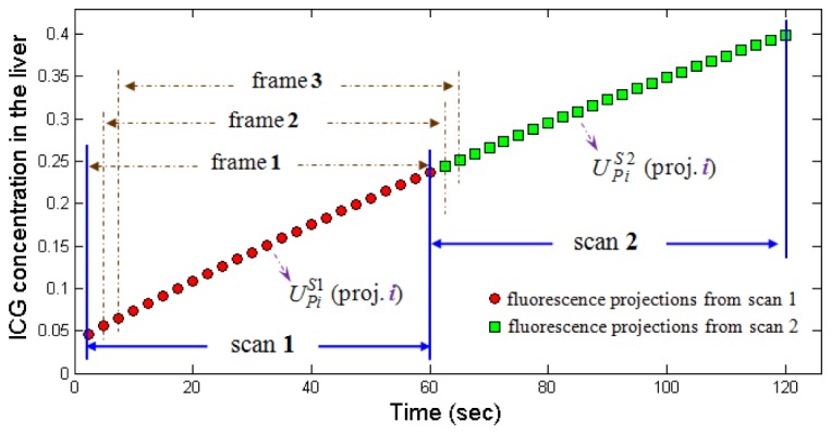
Re-assembling the fluorescence projection sequence. The red points depict ICG concentrations corresponding to different projection angles from scan 1 (acquired during ~0 sec to 60 sec). The green points depict ICG concentrations from scan 2 (acquired during ~60 sec to 120 sec). Here, we assemble the frame 1 using projections from scan 1. We re-assemble the frame 2 using the (K-1) projections from scan 1 and the first projection from scan 2. Similarly, we re-assemble the frame 3 using the (K-2) projections from scan 1 and the first two projections from scan 2.
As shown in Fig. 1, after re-assembling measurement sequence, the reconstruction interval will be determined by the time interval between acquiring two nearby projections, i.e., the rotation time of the rotation stage. As a result, the reconstructions interval (i.e., the time interval between the measurement data) is decreased from (~60 s) to (~2.5 s). In our in vivo experiments [3, 6], the reconstruction interval is generally on second time scale (~2.5 sec/frame, see Table 1).
Table 1. The reconstruction interval in conventional and re-assembling modes.
| Mode | Frame Interval of Reconstruction |
|---|---|
| Conventional assembling mode | 60 sec |
| Re-assembling mode | 2.5 sec |
2.2. 4-D FMT Reconstruction
For fluorescence imaging, after obtaining Green's functions describing the photon density in biological tissues, the forward model can be expressed as follows [7],
| (1) |
where is a vector describing the measurements from the source-detector pairs at the surface of the imaged object, obtained in scan ; is a vector describing the fluorescence distribution to be reconstructed; is a weighted matrix describing photon propagation in biological tissues, which is generated using the diffusion approximation to the radiative transport equation.
To solve the dynamic optical imaging problem, the conventional method estimates each image independently using Eq. (1), and then assembles these results into a time sequence. As mentioned above, a disadvantage of this method is that it cannot consider the temporal correlations within measurement data . Ideally, one should treat the dynamic measurement data as a whole and perform a fully 4-D reconstruction, as follows
| (2) |
where is a series of tomographic images, reconstructed from entire measurement data using a space-time system matrix . Here, is the total number of scans in dynamic imaging experiment. As mentioned above, the computation involved is extensive.
Especially, after re-assembling measurement data using the proposed method, the measurement data will be extended to . Correspondingly, the space-time system matrix will also be changed to a matrix with dimension . As a result, the 4-D imaging model will be changed to
| (3) |
The solving of Eq. (3) further increases the computational burden, leading to exceeding current computational capacities.
To overcome the limitation, in this paper, following the derivation described in our previous study [6], we re-generate the imaging model based on KL transformation, as follows
| (4) |
where is the KL transformed measurement data and is the KL transformed fluorophore distributions. Based on the decorrelation property of the KL transformation, the problem of the fully 4-D spatio-temporal reconstruction can be decoupled into a series of separate reconstructions in the KL domain. That is, we can reconstruct these KL domain images as a sequence of independent reconstructions using the following equation
| (5) |
because they are not coupled, where . Once the few most significant KL components are reconstructed, the entire 4-D fluorescence tomographic sequence can be obtained by performing an inverse KL transformation, as demonstrated in our previous study [6].
In this paper, the reconstruction is performed using the algebraic reconstruction technique (ART) [8]. Note that the non-negativity constraint is not included in reconstruction processes because some of the KL component can be negative. In the implementation, the diffusion equation is solved using COMSOL Multiphysics 3.3 (COMSOL, Inc., Burlington, MA, USA). All the algorithms are coded using Matlab 7.3 (MathWorks, Inc., Natick, MA, USA).
3. Materials
3.1. Experimental setup
The numerical simulation and in vivo experiment were performed based on a hybrid FMT/XCT imaging system [9]. Briefly, the imaged object was fixed on a rotating stage, which allowed rotation of the imaged object for full-angle projection acquisitions. Around the rotation stage, a free-space FMT and micro-XCT imaging system were constructed, respectively. As shown in Fig. 2, the FMT system was placed vertically on the optical bench to acquire optical data of the imaged object, and the micro-XCT system was placed horizontally to acquire structural data of the imaged object. The detailed information on the imaging system could be found in [9].
Fig. 2.
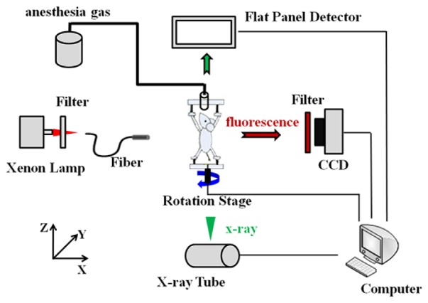
The hybrid FMT/XCT imaging system.
3.2. Numerical simulation
In the numerical simulation, the imaged object was a virtual digital mouse acquired from [10]. The mouse torso from neck to the base of liver was selected as the investigated region, totally 2.6 cm in length. The rotation axis of the mouse was defined as the z-axis with the bottom plane set as cm. Two cylinders (2 mm in diameter and 4 mm in height) were embedded in the liver as fluorescence targets [see the red cylinders in Fig. 3(a)]. The absorption () and scattering () coefficients from [11] were assigned to different organs of the mouse (e.g., heart, lungs, liver, stomach, spleen, and bones), respectively, to simulate photons propagation in heterogeneous tissues. The optical properties outside these organs were regarded as homogeneous. For the imaging, the collimated light beam [see red points in Fig. 3(a)] was modeled as an isotropic point source, located at one mean free path of photon transportation beneath the surface, at the height of 1.3 cm. Referring to [12], here, fluorescence tomography of full view was performed with 24 projections in a step.
Fig. 3.
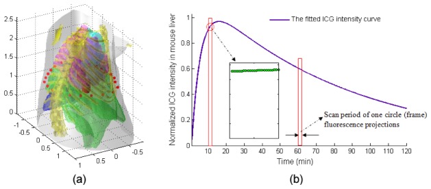
Schematic diagram of the simulation model. (a) The mouse 3-D geometry model used in simulation studies with a length of 2.6 cm from the neck to the base of liver. The red points in (a) represent the excitation point source locations. For each excitation location, the fluorescence is measured from the opposite side within field of view. (b) The intensity curve of ICG in mouse liver, which is normalized by its maximum value. Correspondingly, in forward model, the maximum intensity (concentration) inside the targets is set as 1 unit. Inset shows that ICG intensities for 24 fluorescence projections corresponding to different projection angles from scan 10 (acquired during ~10 min to 11 min).
With the image model, we simulated the time-varying metabolism processes of ICG, which was similar to that described in [13]. Briefly, according to Fig. 3(b), different ICG intensities (concentrations) were set to the two targets at every instant of tomographic data collection process. For example, when collecting the first circle of fluorescence projections (acquired during 0 to ~60 sec), 24 different ICG intensities were set to the two targets at each measured time point. After that, fluorescence projection images from different angles were generated from Eq. (1). Finally, we assembled all synthetics fluorescence projections (total 120 circles, ~120 min) into a time sequence to simulate the entire time-varying ICG metabolic processes.
Here, ICG intensity curve was acquired from [14]. Based on our in vivo experiments [3, 6], the interval of each projection was set to ~2.5 sec. In addition, to simulate the noise effect in the actual measurement, zero-mean, Gaussian noise corresponding to 1% standard error in measurement was added to the synthetic measurement data sets [15].
3.3. In vivo experiment
In the in vivo imaging, an eight-week-old nude mouse, injected with 100 of 50 ICG via tail vein, was suspended on the rotation stage and then continuously rotated 120 circles (~115 min) to monitor the metabolism processes of ICG in the liver. For each circle, 24 fluorescence images (0.2 sec exposure time and CCD binning) were acquired in steps. To correct for optical inhomogeneities, 24 excitation light images (0.03 sec exposure time and CCD binning) were subsequently acquired.
After optical imaging, a hepatobiliary contrast agent (Fenestra LC) was slowly intravenously injected to enhance the anatomical structure of livers in XCT imaging. 60 minutes after the injection of the contrast agent, the mouse was scanned using the micro-XCT system to obtain the anatomical structures of organs.
Finally, a steel anchor point, which could be imaged in both two imaging systems, was plastered on the surface of the mouse to provide the relative height information for registration. Throughout experiments, anesthesia was maintained with an isoflurane veterinary vaporizer.
4. Results
4.1. Simulation study
Figure 4 shows the reconstructed tomographic images of frame 1, obtained by the conventional assembling method and the proposed re-assembling method, respectively. Figures 4(a) and 4(c) show the reconstruction results obtained by the conventional assembling method, where the 120-frame (scan-by-scan) measurement data are used as the input data of the reconstruction. In contrast, Figs. 4(b) and 4(d) show the reconstruction results obtained by the re-assembling method, where the 2880-frame (re-assembled) measurement data are used as the input data of the reconstruction.
Fig. 4.
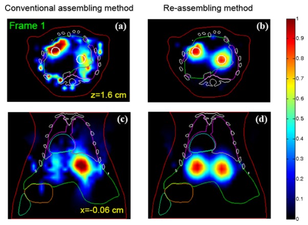
Comparison of the reconstruction results of frame 1, obtained by using the conventional and the re-assembling measurement data. (a) and (c) The reconstruction results obtained by using the conventional assembled measurement data (120-frame). (b) and (d) The reconstruction result obtained by using the re-assembled measurement data (2880-frame). The white circles in (a) and (b) depict the actual boundary of the fluorescence target. For the reconstruction in KL domain, the volume of interest is of and sampled to voxels. The 6,365 voxels inside the imaged object and 16,841 source-detector pairs are used. Note that the non-negativity constraint is not included in the reconstruction, which is necessary because some of the KL component can be negative. In addition, the same imaging model is used in the two assembling modes. All images are displayed in the same range.
To eliminate the temporal correlations within measurement data, here, the conventional or re-assembled measurement sequences were reconstructed by the KL-based method. In detail, we firstly applied KL transformation to the measurement sequence (conventional or re-assembled) then reconstructed the first 2 KL components in KL domain using ART. After that, the entire tomographic image sequence (120-frame or 2880-frame) was obtained by performing an inverse KL transformation. Based on the “scree method” [16], in the case, the first 2 KL components were retained and then reconstructed.
For reconstruction in KL domain, in detail, the volume of interest was a 3-D region and sampled to voxels. Only 6,365 voxels inside the imaged object and 16,841 source-detector pairs were used in the reconstruction processes. The reconstruction was terminated after 50 ART iterations and the relaxation parameter was . These parameters were generic values used in the previous experiments. Note that the non-negativity constraint was not included in the reconstruction because some of the KL component could be negative. In addition, the same imaging model was used in the two assembling methods.
The results indicate that it is quite difficult to resolve the two fluorescence target based on the conventional assembling method (see Figs. 4(a) and 4(c)). In contrast, when the re-assembled measurement data are used as the input data of 4-D reconstruction, we can resolve the two fluorescence targets based on the KL-based reconstruction method, as shown in Figs. 4(b) and 4(d). The main reason may be that the principle of the KL-based reconstruction method is to make full use of the temporal correlations within measurement data in reconstruction processes. After re-assembling the measurement data, the time interval between the input data will greatly reduce. As a result, it will be helpful for improving the reconstruction performance of the KL-based method, especially when the fluorophore's concentration change significantly in the short time interval, as demonstrated in the case. However, when the fluorophore's concentrations have no significant change in the short time interval, it will be difficult to clarify whether the reconstruction quality of the KL-based method can be improved.
Figure 5 shows the reconstructed FMT image sequence, which is acquired about 1 min after imaging (frames 1~24). These fluorescence tomographic images are obtained by the KL-based reconstruction method, retaining the first 2 KL components, in which the 2880-frame (re-assembled) measurement data are used as the input data of the reconstruction. The results suggest that if using the conventional assembling method, only one tomographic image [Fig. 5(a)] can be obtained based on the acquired 24 projections from scan 1. For comparison, based on the same projection data, 24 tomographic images can be obtained when using the proposed re-assembling method. That is, after re-assembling projection sequence, the frame interval of reconstruction is reduced from 1 min (the conventional resemble method) to ~2.5 sec, which will be helpful for observing the fast biological activities.
Fig. 5.
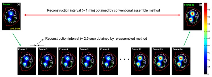
The reconstructed FMT images acquired about 1 min after imaging (frames 1~24). After re-assembling projection sequence, the reconstruction interval is reduced from 1 min (the conventional resemble method) to ~2.5 sec. These fluorescence images are reconstructed by the KL-based method, retaining the first 2 KL components in the reconstruction processes. All images are displayed in the same range.
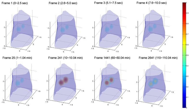
Figure 6 shows the 3-D rendering of the reconstructed FMT image sequence, where 2880-frame (re-assembled) measurement data are used as the input data of the reconstruction. In the reconstruction, the entire tomographic image sequence (2880-frame) is obtained by the KL-based reconstruction method, incorporating the first 2 KL components retained. The results suggest that the reconstructed 3-D FMT images provide a good image quality, where the two fluorescence targets can be clearly resolved. In addition, it can also be observed that we can only acquire the 120-frame tomographic image sequence based on the conventional assembling method. In contrast, we can acquire the 2880-frame tomographic image sequence when using the re-assembling method. Further, we can also find that when using the re-assembling method, the length of the reconstruction sequence increases greatly, compared with the conventional assembling method. But, the computational time does not significantly increase based on the compression property of the KL transformation (see Table 2). The main reason is that no matter what is to recover the 120-frame (the conventional assembling method) or 2880-frame (the re-assembling method) tomographic image sequence, only the fewer KL components need be retained and then be reconstructed. As a result, it leads to a similar computational time (see Table 2). Here, the computation was performed on a personal computer, with 2.8 GHz Quad processor and 24 GB RAM.
Fig. 6.
The 3-D rendering of the reconstructed images at different time points. These reconstructed images (frames 1, 2, 3, 4, 25, 241, 1441, and 2641) are obtained by the proposed re-assembling method combined with the KL-based reconstruction method. In the case, the 2880-frame (re-assembled) measurement data are used as the input data of the reconstruction. For KL reconstruction, the first 2 KL components are retained and reconstructed. All images are displayed in the same range.
Table 2. Comparison of computational times for different assembling modes in the numerical simulation.
| Method | Computational Time |
|||
|---|---|---|---|---|
| Reconstruction | KL | Inverse KL | Total Time | |
| Conventional assembling method | ~8.1 min | ~0.4 sec | ~0.1 sec | ~8.1 min |
| Re-assembling method | ~8.1 min | ~4.1 min | ~0.1 sec | ~12.2 min |
Figure 7 shows the time course of ICG in the fluorescence target, which is obtained by calculating the mean concentrations of ICG from the reconstructed image sequence through all time points. The green asterisks in Fig. (7) depict the ICG time course obtained by using the re-assembled measurement data (2880-frame). In contrast, the black rectangles in Fig. (7) depict the ICG time course obtained by using the conventional assembled measurement data (120-frame).
Fig. 7.
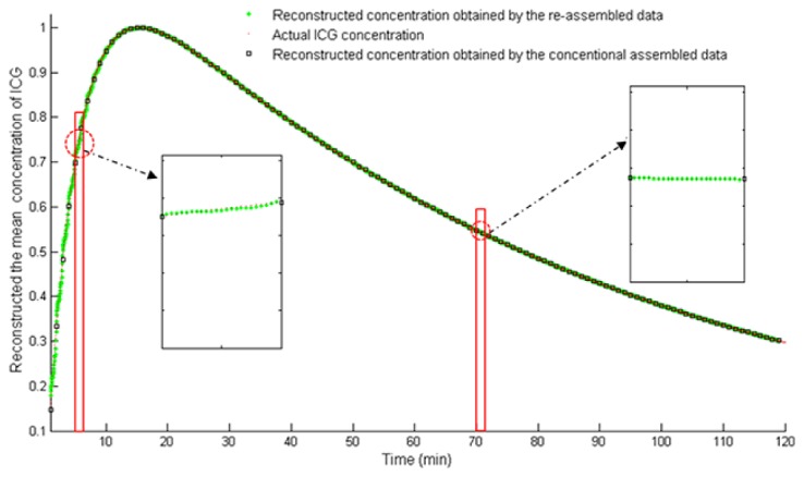
The time course of ICG in the fluorescence targets, which is obtained by calculating the mean concentrations of ICG from the reconstructed image sequence through all time points. The green asterisks depict the ICG time course obtained by using the re-assembled measurement data (2880-frame). The black rectangles depict the ICG time course obtained by using the conventional assembled measurement data (120-frame). The red points depict the actual ICG concentrations (2880).
4.2. In vivo experiment
Figure 8 depicts the reconstruction images from the in vivo experiment that are imaged about 8 min after injecting ICG. Figures 8(b) and 8(c) show the reconstruction results, where the conventional (120-frame) and re-assembled (2880-frame) measurement data are used as the input data of reconstruction, respectively. Similar to the numerical simulation, here, the conventional or re-assembled measurement sequences were reconstructed by the KL-based method. Referring to “scree method” [16], in the case, the first 5 KL components were retained and then reconstructed. In detail, for reconstruction in KL domain, the volume of interest was a 3-D region and sampled to voxels. 5,466 voxels inside the imaged object and 19,980 source-detector pairs were used for reconstruction. In the case, the number of ART iterations was fixed to 2 and the relaxation parameter was , selected experimentally based on the results. A larger iteration number did not produce an obvious improvement but required more computation time. In addition, to improve the reconstruction quality in the in vivo experiment, the reconstruction was performed incorporating a heterogeneous forward model. Here, the forward model was constructed by assigning the midrange average optical properties [17] to the heart, lungs, liver, and bones, which could provide an acceptable error of reconstructions in the mouse chest [18]. Note that the non-negativity constraint was not included in the reconstruction because some of the KL component could be negative. In addition, the same imaging model was used in the two assembling methods.
Fig. 8.
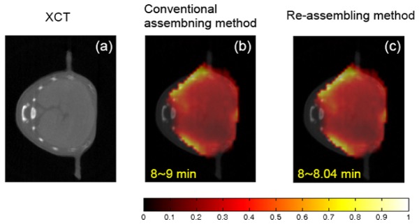
The reconstruction results from the dynamic in vivo experiment, obtained by using the conventional and the re-assembled measurement data. (a) The x-ray computed tomography image of liver region. (b) and (c) The corresponding fluorescence tomographic images that are imaged about 8 min after ICG injection. (b) The reconstruction results obtained by using the conventional assembled measurement data (120-frame). (c) The reconstruction result obtained by using the re-assembled measurement data (2880-frame). The conventional assembled or re-assembled measurement sequences are reconstructed by the KL-based method. The volume considered for reconstruction is a 3-D region and sampled to voxels. The 5,466 voxels inside the imaged object and 19,980 source-detector pairs are used in the reconstruction process of KL domain. The same imaging model is used in the two assembling modes. To improve the reconstruction quality in in vivo experiment, the reconstruction is performed incorporating a heterogeneous forward model. All images are displayed at the same range.
The experimental results show that the reconstructed bio-distributions mainly accumulate in the liver of the mouse. At the initial stage of the injection of ICG, the bio-distributions of ICG within mouse may accumulate in the liver. By comparing with the anatomical structure of the liver provided by the XCT image, we think that the re-assembling method combined with the KL-based reconstruction method can provide a good reconstruction quality. On the other hand, we also find that there are no significant differences between the reconstruction results obtained by the conventional assembling and re-assembling methods. The main reason may be that in the in vivo experiment, compared to other factors (e.g., light scattering in different organs, the effect of noise, etc), the temporal correlations in measurement data may not be the most important factor affecting the visual quality of FMT.
Figure 9 depicts the reconstructed FMT image sequence acquired about 1 min after the injection of ICG (frames 1~24), where 2880-frame (re-assembled) measurement data are used as the input data of the reconstruction. For reconstruction, these fluorescence tomographic images are obtained by the KL-based reconstruction method, retaining the first 5 KL components. Similar to the simulation study, if using the conventional assembling method, only one tomographic image [Fig. 9(a)] can be obtained based on the acquired 24 projection data from scan 1. For comparison, when using the re-assembling method, 24 tomographic images can be obtained (~2.5 sec/frame) based on the same projection data.
Fig. 9.
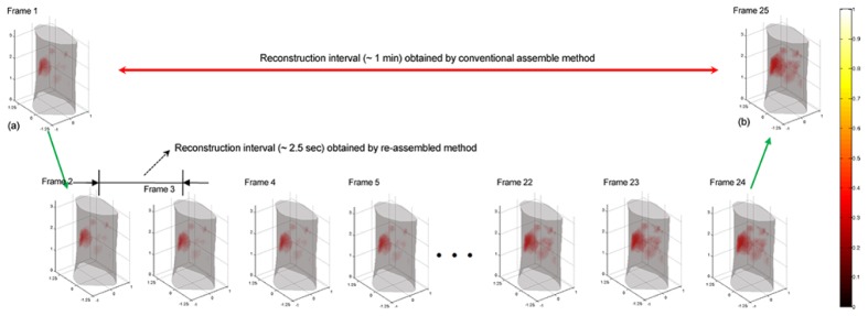
The reconstructed FMT image sequence from the dynamic in vivo imaging study, acquired about 1 min after injecting ICG (frames 1~24). The results indicate that after re-assembling projection sequence, the frame interval of reconstruction is reduced from 1 min (the conventional resemble method) to ~2.5 sec. Here, the tomographic sequence is obtained by the KL-based reconstruction method, incorporating the first 5 KL components retained. All images are displayed in the same range.
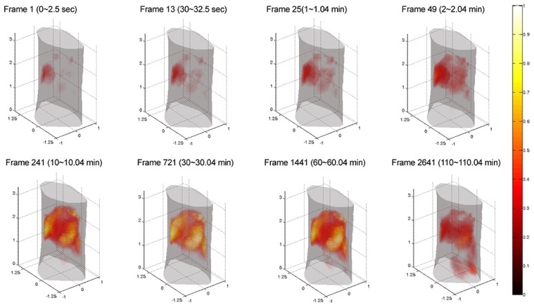
Figure 10 depicts the time series of 3-D FMT renderings acquired after the injection of ICG, which is obtained by the proposed re-assembling method combined with the KL-based method (the first 5 KL components retained). Frames at different time points are selected to show the metabolic processes of ICG in the mouse liver. Note that in the case, the total computational time for the re-assembling method is relative longer than that for the conventional assembling method (see Table 3). The main reason is that when using the re-assembling method, the scale of KL matrix is larger rather than that generated by the conventional assembling method, leading to a long computational time. But, it can also be observed that there are no significant differences in the reconstruction time obtained by the two assembling modes (see the second column of Table 3) based on the compression property of KL transformation.
Fig. 10.
The 3-D rendering of the reconstructed images at different time points from in vivo experiment. These reconstructed image (frames 1, 13, 25, 49, 241, 721, 1441, and 2641) are obtained by the proposed re-assembling method combined with the KL-based reconstruction method (the first 5 KL components retained). Here, the 2880-frame (re-assembled) measurement data are used as the input data of the reconstruction. All images are displayed in the same range.
Table 3. Comparison of computational times for different assembling methods in the in vivo experiment.
| Method | Computational Time |
|||
|---|---|---|---|---|
| Reconstruction | KL | Inverse KL | Total Time | |
| Conventional assembling method | ~46.8 sec | ~0.2 sec | ~0.1 sec | ~0.8 min |
| Re-assembling method | ~46.3 sec | ~4.1 min | ~0.1 sec | ~4.9 min |
Correspondingly, the time course of ICG in the mouse liver, obtained by calculating the mean concentrations of ICG from the reconstructed image sequence, is shown in Fig. 11. In Fig. 11, the green asterisks and black rectangles describe the ICG time course obtained by using the re-assembled measurement data (2880-frame) and the conventional assembled measurement data (120-frame), respectively. Further, the pharmacokinetic parameters of ICG in the liver, reflecting the uptake and excretion rate constants respectively, are estimated using a two compartmental model [19]
| (6) |
where is the ICG concentration curve. and are the uptake and excretion rates, respectively. A and B are the zero time intercepts. The fitted ICG time course (see the red line) and the obtained uptake and excretion rates are also shown in Fig. 11.
Fig. 11.
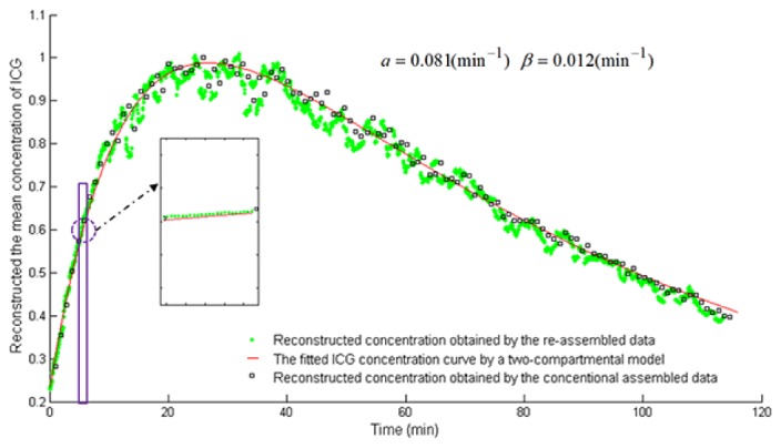
The time course of ICG in the mouse liver in vivo. The X axis represents the time (min). The Y axis represents the mean concentrations of ICG, which are normalized by its maximum value. The green asterisks and black rectangles describe ICG time course obtained by using the re-assembled measurement data (2880-frame) and the conventional assembled measurement data (120-frame), respectively. The red line describes the fitted ICG time course using a two compartmental model [19].
5. Discussion and conclusion
Dynamic FMT imaging allows fast and non-invasively resolving the 3-D distribution of fluorescence bio-markers within small animal in vivo, which is helpful for bio-medical research. However, reconstruction of the dynamic FMT is a challenging problem. In our previous study [6], by using KL transformation, we implemented a fully 4-D reconstruction approach. However, in the reconstruction processes, the input data were from scan-by-scan fluorescence projections, which led to a long reconstruction interval (typically >1 min). In contrast, the main aim of this paper was to reduce the reconstruction interval of dynamic FMT imaging, which was achieved by re-assembling the acquired fluorescence projection sequence. Practically, to make full use of the temporal correlations within measurement data in 4-D reconstruction, the re-assembled image sequence was reconstructed by the KL-based method.
It was observed from the numerical simulation and in vivo experimental results that after re-assembling measurement sequence, the reconstruction interval between two nearby frames was reduced from ~1 min/frame to ~2.5 sec/frame (Figs. 1, 5, 9, and Table 1), which was helpful for imaging fast biological activities. In addition, we could also find that in the numerical simulation, when using the re-assembled measurement data, the KL-based reconstruction method could provide a good reconstruction quality (Fig. 4) compared with the conventional assembling method, where the two fluorescence targets could be clear resolved. In in vivo experiments, there were no significant visual differences in the reconstruction images obtained by using the conventional and re-assembled measurement data (Fig. 8). The main reason might be that compared with other factors affecting in vivo image quality of FMT (e.g., light scattering in different tissues, the effect of noise, etc), the temporal correlations in measurement data (i.e., the reduced time interval in measurement data) may be not the critical factor. Further, whatever the conventional assembled sequence (120-frame) or the re-assembled sequence (2880-frame) is used as the input data of 4-D reconstruction, based on the compression property of KL, there is only fewer KL components need be retained and then be reconstructed to recover the entire tomographic sequence. As a result, there are no significant differences in the reconstruction time (see the second column of Table 2 and Table 3). However, when using the re-assembled measurement data, the scale of KL matrix is relative larger, which increase the total computational time.
Based on the above results, we believe that the proposed method provides an attractive technique for solving the dynamic FMT reconstruction problem. First, this technique allows to achieve the 3-D FMT imaging at a high reconstruction interval (e.g., ~2.5 sec/frame implemented in this work). In addition, the reconstruction interval can be further shortened when a fast rotation speed is used. As a result, the technique is helpful for imaging fast biological activities. Further, this method is fairly flexible to extend to other optical imaging modalities, e.g., bioluminescence tomography (BLT).
It should be noted that a non-negativity constraint cannot be imposed in KL domain reconstruction because the KL components may be negative. However, this may affect reconstruction quality of FMT. In addition, in this paper, the data acquisition time has not been reduced. To improve the imaging time resolution, the limited-view reconstruction method can be used [20]. On the other hand, we should also note the total computational time for the re-assembling method is relative longer than that for the conventional assembling method. To reduce the computational time, the graphics processing unit (GPU) acceleration [21] can be considered as a effective method. Moreover, in the in vivo experiment, a thorough investigation of the reconstruction accuracy is not yet conducted. To validate the reconstruction results from in vivo experiment, the multispectral epi-illumination cryoslicing imaging experiment may be performed [22]. Further, more complex in vivo experiments (e.g., the use of specific imaging agents in tumor models) should also be considered, which will further extend the application of FMT in vivo. Finally, during the acquisition process of one circle of fluorescence projections, the fluorophore concentration continuously varied. However, only one image is reconstructed in the imaging processes. As a result, it is difficult to clarify what is the specific time point indicated by the reconstruction result. The problem may be solved by the time-varying optical tomographic reconstruction method e.g., the state-estimation method [23]. These related work will be investigated in our future study.
In conclusion, based on the re-assembling method and KL-based reconstruction method, we have proposed a new approach for solving the dynamic FMT problem. The method provides a high reconstruction interval and a good image quality, which will be helpful for resolving fast kinetic behaviors within small animals in vivo.
Acknowledgments
This work is supported by the National Natural Science Foundation of China under Grant No. 81371604, 81230035, 81071220, and 61372046; the Shaanxi Natural Science Foundation under Grant No. 2013JM4008.
References and links
- 1.Patwardhan S., Bloch S., Achilefu S., Culver J., “Time-dependent whole-body fluorescence tomography of probe bio-distributions in mice,” Opt. Express 13(7), 2564–2577 (2005). 10.1364/OPEX.13.002564 [DOI] [PubMed] [Google Scholar]
- 2.Vasquez K. O., Casavant C., Peterson J. D., “Quantitative whole body biodistribution of fluorescent-labeled agents by non-invasive tomographic imaging,” PLoS ONE 6(6), e20594 (2011). 10.1371/journal.pone.0020594 [DOI] [PMC free article] [PubMed] [Google Scholar]
- 3.Liu X., Guo X., Liu F., Zhang Y., Zhang H., Hu G., Bai J., “Imaging of indocyanine green perfusion inmouse liver with fuorescence diffuse optical tomography,” IEEE Trans. Biomed. Eng. 58(8), 2139–2143 (2011). 10.1109/TBME.2011.2135858 [DOI] [Google Scholar]
- 4.Kolehmainen V., Prince S., Arridge S. R., Kaipio J. P., “State-estimation approach to the nonstationary optical tomography problem,” J. Opt. Soc. Am. A 20(5), 876–889 (2003). 10.1364/JOSAA.20.000876 [DOI] [PubMed] [Google Scholar]
- 5.Prince S., Kolehmainen V., Kaipio J. P., Franceschini M. A., Boas D., Arridge S. R., “Time-series estimation of biological factors in optical diffusion tomography,” Phys. Med. Biol. 48(11), 1491–1504 (2003). 10.1088/0031-9155/48/11/301 [DOI] [PubMed] [Google Scholar]
- 6.Liu X., Zhang B., Luo J., Bai J., “4-D reconstruction for dynamic fluorescence diffuse optical tomography,” IEEE Trans. Med. Imaging 31(11), 2120–2132 (2012). 10.1109/TMI.2012.2213828 [DOI] [PubMed] [Google Scholar]
- 7.O’Leary M. A., Boas D. A., Li X. D., Chance B., Yodh A. G., “Fluorescence lifetime imaging in turbid media,” Opt. Lett. 21(2), 158–160 (1996). 10.1364/OL.21.000158 [DOI] [PubMed] [Google Scholar]
- 8.A. Kak and M. Slaney, Computerized Tomographic Imaging (New York: IEEE Press, 1987), ch. 7. [Google Scholar]
- 9.Guo X., Liu X., Wang X., Tian F., Liu F., Zhang B., Hu G., Bai J., “A combined fluorescence and microcomputed tomography system for small animal imaging,” IEEE Trans. Biomed. Eng. 57(12), 2876–2883 (2010). 10.1109/TBME.2010.2073468 [DOI] [PubMed] [Google Scholar]
- 10.Dogdas B., Stout D., Chatziioannou A. F., Leahy R. M., “Digimouse: A 3D whole body mouse atlas from CT and cryosection data,” Phys. Med. Biol. 52(3), 577–587 (2007). 10.1088/0031-9155/52/3/003 [DOI] [PMC free article] [PubMed] [Google Scholar]
- 11.Alexandrakis G., Rannou F. R., Chatziioannou A. F., “Tomographic bioluminescence imaging by use of a combined optical-PET (OPET) system: A computer simulation feasibility study,” Phys. Med. Biol. 50(17), 4225–4241 (2005). 10.1088/0031-9155/50/17/021 [DOI] [PMC free article] [PubMed] [Google Scholar]
- 12.Wang D., Liu X., Bai J., “Analysis of fast full angle fluorescence diffuse optical tomography with beam-forming illumination,” Opt. Express 17(24), 21376–21395 (2009). 10.1364/OE.17.021376 [DOI] [PubMed] [Google Scholar]
- 13.Liu X., Liu F., Bai J., “A linear correction for principal component analysis of dynamic fluorescence diffuse optical tomography images,” IEEE Trans. Biomed. Eng. 58(6), 1602–1611 (2011). 10.1109/TBME.2011.2106501 [DOI] [PubMed] [Google Scholar]
- 14.Chen Q., Mao S., Bai J., “In vivo measurement of indocyanine green biodistribution in mammalian organs using fiber based system,” Proc. SPIE-OSA-IEEE Asia Communications and Photonics 7634, 76340C (2009). 10.1117/12.851851 [DOI] [Google Scholar]
- 15.Roy R., Sevick-Muraca E., “Truncated Newton’s optimization scheme for absorption and fluorescence optical tomography: Part II reconstruction from synthetic measurements,” Opt. Express 4(10), 372–382 (1999). 10.1364/OE.4.000372 [DOI] [PubMed] [Google Scholar]
- 16.Cattell R. B., “The scree test for the number of factors,” Multivariate Behav. Res. 1(2), 245–276 (1966). 10.1207/s15327906mbr0102_10 [DOI] [PubMed] [Google Scholar]
- 17.Niedre M. J., Turner G. M., Ntziachristos V., “Time-resolved imaging of optical coefficients through murine chest cavities,” J. Biomed. Opt. 11(6), 064017 (2006). 10.1117/1.2400702 [DOI] [PubMed] [Google Scholar]
- 18.Hyde D., Schulz R., Brooks D., Miller E., Ntziachristos V., “Performance dependence of hybrid x-ray computed tomography/fluorescence molecular tomography on the optical forward problem,” J. Opt. Soc. Am. A 26(4), 919–923 (2009). 10.1364/JOSAA.26.000919 [DOI] [PubMed] [Google Scholar]
- 19.Shinohara H., Tanaka A., Kitai T., Yanabu N., Inomoto T., Satoh S., Hatano E., Yamaoka Y., Hirao K., “Direct measurement of hepatic indocyanine green clearance with near-infrared spectroscopy: separate evaluation of uptake and removal,” Hepatology 23(1), 137–144 (1996). 10.1002/hep.510230119 [DOI] [PubMed] [Google Scholar]
- 20.Liu X., Liao Q., Wang H., “Fast X-ray luminescence computed tomography imaging,” IEEE Trans. Biomed. Eng. 61(6), 1621–1627 (2014). 10.1109/TBME.2013.2294633 [DOI] [PubMed] [Google Scholar]
- 21.NVIDIA Corporation, NVIDIA CUDA C Programming Guide 4.0 (2011).
- 22.Sarantopoulos A., Themelis G., Ntziachristos V., “Imaging the bio-distribution of fluorescent probes using multispectral epi-illumination cryoslicing imaging,” Mol. Imaging Biol. 13(5), 874–885 (2011). 10.1007/s11307-010-0416-8 [DOI] [PubMed] [Google Scholar]
- 23.Prince S., Kolehmainen V., Kaipio J. P., Franceschini M. A., Boas D., Arridge S. R., “Time-series estimation of biological factors in optical diffusion tomography,” Phys. Med. Biol. 48(11), 1491–1504 (2003). 10.1088/0031-9155/48/11/301 [DOI] [PubMed] [Google Scholar]


