Abstract
Filamentous actin (F-actin) is the major protein of muscle thin filaments, and actin microfilaments are the main component of the eukaryotic cytoskeleton. Mutations in different actin isoforms lead to early-onset autosomal dominant non-syndromic hearing loss1, familial thoracic aortic aneurysms and dissections2, and multiple variations of myopathies3. In striated muscle fibres, the binding of myosin motors to actin filaments is mainly regulated by tropomyosin and troponin4,5. Tropomyosin also binds to F-actin in smooth muscle and in non-muscle cells and stabilizes and regulates the filaments there in the absence of troponin6. Although crystal structures for monomeric actin (G-actin) are available7, a high-resolution structure of F-actin is still missing, hampering our understanding of how disease-causing mutations affect the function of thin muscle filaments and microfilaments. Here we report the three-dimensional structure of F-actin at a resolution of 3.7 ångstroms in complex with tropomyosin at a resolution of 6.5ångstroms, determined by electron cryomicroscopy. The structure reveals that the D-loop is ordered and acts as a central region for hydrophobic and electrostatic interactions that stabilize the F-actin filament. We clearly identify the density corresponding to ADP and Mg2+ and explain the possible effect of prominent disease-causing mutants. A comparison of F-actin with G-actin reveals the conformational changes during filament formation and identifies the D-loop as their key mediator. We also confirm that negatively charged tropomyosin interacts with a positively charged groove on F-actin. Comparison of the position of tropomyosin in F-actin–tropomyosin with its position in our previously determined actin–tropomyosin–myosin structure8 reveals a myosin-induced transition of tropomyosin. Our results allow us to understand the role of individual mutations in the genesis of actin- and tropomyosin-related diseases and will serve as a strong foundation for the targeted development of drugs.
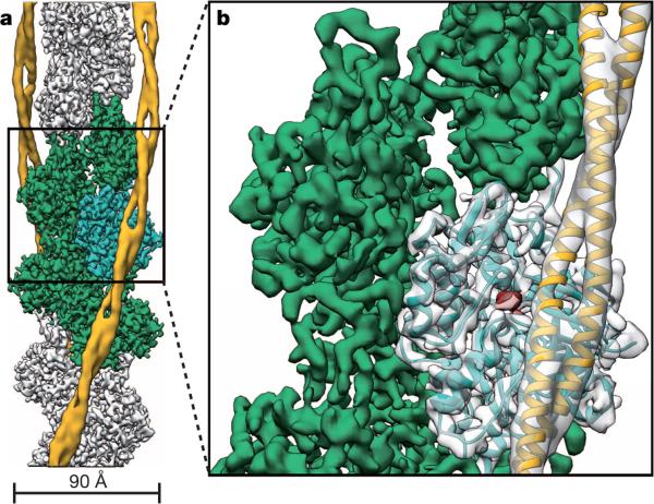
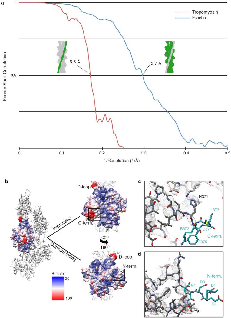
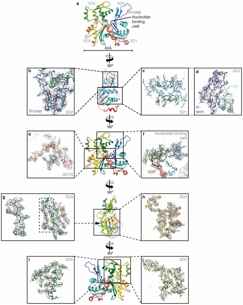
To determine the structure of F-actin is inherently difficult because of its flexibility and its resistance to crystallization. Therefore, the only structural models of F-actin so far have been determined either from medium-resolution electron cryomicroscopy (cryo-EM) maps9–13 or by interpreting X-ray fibre diffraction data14, which has certain limitations. Using a direct electron detector and drift correction and by improving the image processing of helical specimens (see Methods), we have determined the structure of F-actin in complex with tropomyosin at an average resolution of 3.7 Å for F-actin and 6.5 Å for tropomyosin using cryo-EM (Fig. 1a, Extended Data Fig. 1a, b, 2a, Supplementary Video 1). During refinement the helical parameters—that is, the rise per subunit and the azimuthal rotation—were estimated to be 27.5 Å and 166.4°, respectively (see Methods). The side-chain densities of most actin residues were clearly resolved (Extended Data Fig. 3, Supplementary Video 2) and allowed us to build an atomic model of F-actin (Fig. 1b, Extended Data Fig. 3). The first four residues of the amino terminus and the last four residues of the carboxy terminus were not resolved (Extended Data Fig. 2b–d), indicating that these regions are disordered in the filament. However, we could clearly identify density corresponding to ADP and the coordinated cation, which is most probably Mg2+ (Fig. 1b, Extended Data Fig. 3a).
Figure 1. Cryo-EM structure of F-actin decorated with tropomyosin.
a, Full cryo-EM reconstruction of F-actin (grey, with five central subunits in green and one subunit in cyan) decorated with tropomyosin (yellow). b, Close-up view of a with the atomic and molecular model of an F-actin subunit (cyan) and tropomyosin (yellow) and their corresponding densities, respectively. The density corresponding to ADP is depicted in red.
The overall organization of F-actin is similar to that described in previous structures and models10,14. However, given the superior resolution of our structure, we could clearly identify many salt bridges and therefore directly reveal intra- and intermolecular interactions of the F-actin filament in detail (Extended Data Fig. 4a).
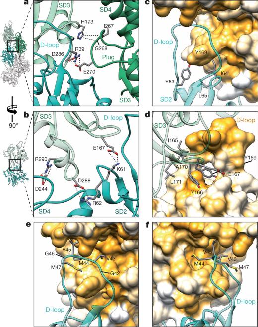
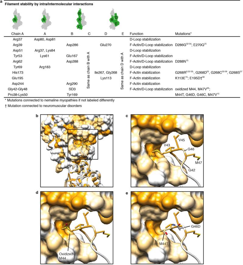
F-actin is composed of two long-pitch helical strands. Interactions between actin subunits of the same strand and the opposing strand—the so-called intrastrand and interstrand interactions, respectively—stabilize the F-actin filament (Fig. 2, Extended Data Figs 4 and 5). Intrastrand contacts are mediated by subdomains SD2 and SD4 of one part of the actin strand with the SD3 of the adjacent part of the actin strand (Fig. 2a). Besides several salt bridges between the edges of SD4 and SD3 (Fig. 2b), the major site of interaction is between the D-loop and the bottom of the β-sheet of SD3 (Fig. 2c–f, Extended Data Fig. 4b–e). The D-loop encloses tyrosine 169 of the neighbouring subunit, resembling a lock-and-key interaction (Fig. 2c). In addition, adjacent residues fit snugly into the groove formed by regions next to the D-loop around isoleucine 64 (Fig. 2d) and a prominent hydrophobic patch in the D-loop interacts with a hydrophobic groove on the neighbouring F-actin subunit (Fig. 2e, f). Thus, the intrastrand interface at this position is large and is stabilized not only by electrostatic and hydrophobic interactions but also by geometric surface complementarity. As expected, mutations at this site (which, for instance, induce charges at hydrophobic interfaces) hamper F-actin polymerization and stability (Extended Data Fig. 4d, e) and can lead to different forms of nemaline myopathy3,15 (Extended Data Fig. 4a).
Figure 2. Filament stability by intrastrand and interstrand interactions.
a–f, Neighbouring F-actin subunits stabilize the F-actin filament by interaction through salt bridges (a, b) and by hydrophobic interactions (c–f). The central F-actin subunit is depicted in cyan, and adjacent subunits are shown in shades of green. Surfaces are coloured from high (yellow) to low (white) hydrophobicity. Oxygen is coloured red, nitrogen is blue, carbon is grey and hydrogen is colourless. Interactions between amino acids are highlighted with dotted lines. a, Interstrand and intrastrand salt bridges of three actin subunits involving the plug. b, Several intrastrand salt bridges at the actin–actin interface. c–f, Front view (c, e), back view (d) and side view (f) of the D-loop interacting with the SD3 of the neighbouring intrastrand F-actin subunit. The D-loop wraps around Y169 of the neighbouring subunit and other residues snugly fit into the groove formed by regions adjacent to the D-loop (c, d), resembling a lock-and-key interaction. In addition, a prominent hydrophobic patch in the D-loop interacts with a hydrophobic groove on the neighbouring F-actin subunit (e, f).
In contrast to most G-actin structural models, in which the D-loop is not resolved owing to its high flexibility, the D-loop is well defined in our structure (Extended Data Fig. 3b), corroborating its importance in mediating actin–actin interaction. It also contrasts with results of medium-resolution cryo-EM data12 and disulphide cross-linking studies16 that suggested the presence of multiple D-loop conformational states. In addition, these and other studies17,18 suggested a close interaction of the D-loop with the C terminus of actin. Although the C terminus is located next to the D-loop, it is not resolved in the cryo-EM density (Extended Data Fig. 2c), indicating that the interaction between these two regions is either transient or structurally flexible.
Our structural determination also gives a possible explanation for the recently described F-actin disassembly by Mical, a multidomain cytosolic actin regulator19. Mical post-translationally oxidizes methionine 44 within the D-loop of actin20, leading to the less flexible and more hydrophilic sulfoxide. The increased polarity could lead to a weakening of the hydrophobic actin–actin interaction (Extended Data Fig. 4d) and consequently to a Mical-induced disassembly of the F-actin filament.
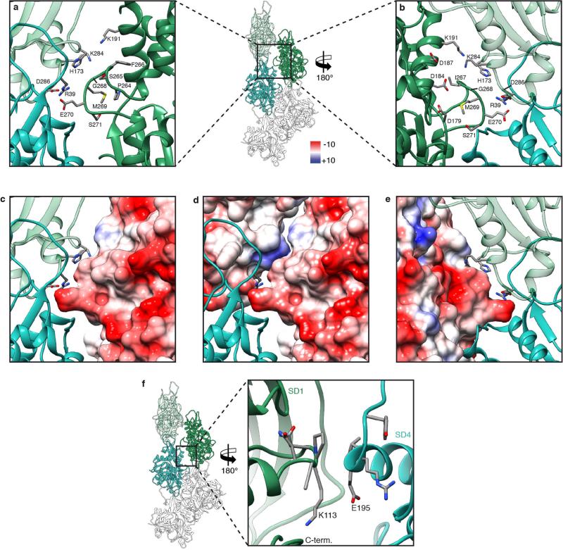
The F-actin structure confirms that the so-called hydrophobic plug9 connects three F-actin subunits with each other (Fig. 2a). However, as suggested previously10, this interstrand interaction is formed by salt bridges (Fig. 2a), not by hydrophobic interactions (Extended Data Fig. 5a–e). A large part of the plug is negatively charged on the surface, electrostatically interacting with a positively charged patch on the opposing actin, with histidine 173 and lysine 284 at its centre (Extended Data Fig. 5c–e). Another possible salt bridge connects two neighbouring actins at lysine 113 of SD1 and glutamate 195 of SD4 (Extended Data Fig. 5f). However, the interface atthis position is quite small and not surrounded by other prominent electrostatic or hydrophobic interactions. In general, the two strands of F-actin are held together by only a few contacts, and a large empty space is maintained between the strands. This is probably an important requisite for the flexibility of F-actin filaments.
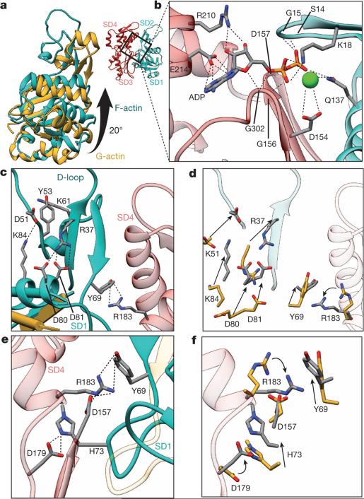
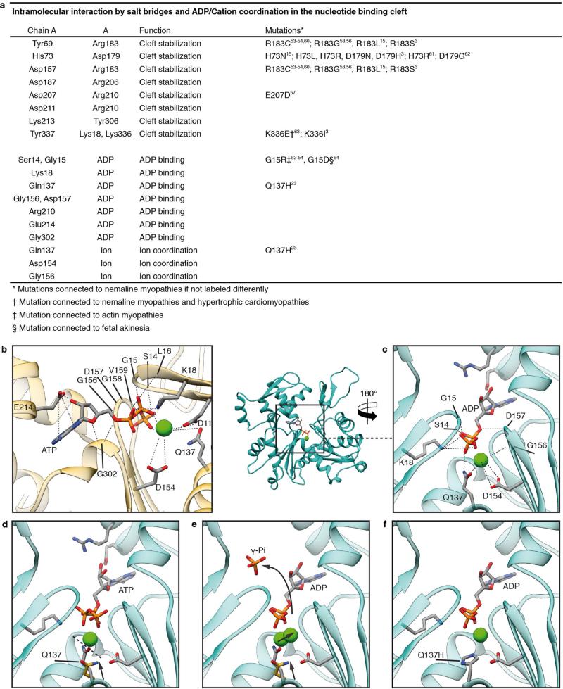
As previously described9,10,14, F-actin is more flattened than is G-actin because of a rotation of SD1 and particularly SD2 (Fig. 3a, Supplementary Video 3). New salt bridges between SD1, SD4 and SD2 stabilize the new interface between the opposing subdomains at the nucleotide-binding cleft (Fig. 3b–f, Extended Data Fig. 6a).
Figure 3. G-actin to F-actin transition.
a, A global rotation of SD1 and SD2 leads to a flattening of G-actin (yellow) during transition to F-actin (cyan). b, Coordination of ADP and a cation in the nucleotide binding cleft in F-actin (SD1–SD2 cyan, SD3–SD4 red). The cation is most probably Mg2+. However, Ca2+ cannot be excluded as the coordinated cation because the actin was purified in Ca2+-containing buffer. c–f, The conformation of F-actin is finally stabilized by intramolecular interactions between SD2, SD1 and SD4 (c, e). Most of the residues involved in the stabilization of the F-actin conformation show a considerable movement during the transition between G-actin and F-actin (d, f). a, G-actin with defined D-loop for better visualization; PDB accession code 1J6Z. c–f, ATP-bound G-actin; PDB accession code 3EL2.
The coordination of ADP and the divalent cation in the nucleotide-binding cleft by nearby residues is very similar to that in G-actin (Fig. 3b, Extended Data Fig. 6b). However, glutamine 137, which has been shown to play a central role in ATP hydrolysis21, is clearly moved closer to ADP, coordinating not only the cation (as in G-actin) but also the nucleotide β-phosphate (Extended Data Fig. 6c, d, Supplementary Video 3). Interestingly, the presence of ATP instead of ADP in the nucleotide-binding site would be sterically unfavourable (Extended Data Fig. 6d, Supplementary Video 3), suggesting that a different intermediate conformation exists for F-actin–ATP. High-resolution crystal structures of non-vertebrate actin showed that glutamine 137 positions the nucleophilic water that attacks the γ-phosphate of ATP22. Therefore, as previously suggested14, the shorter distance of glutamine 137 to the γ-phosphate probably induces ATP hydrolysis and then afterwards the cation takes the position of the γ-phosphate in the finally resulting ADP-binding-state (Extended Data Fig. 6e, Supplementary Video 3). A mutation of glutamine 137 connected to nemaline myopathy23 further highlights the importance of this residue in the proper function of F-actin (Extended Data Fig. 6f).
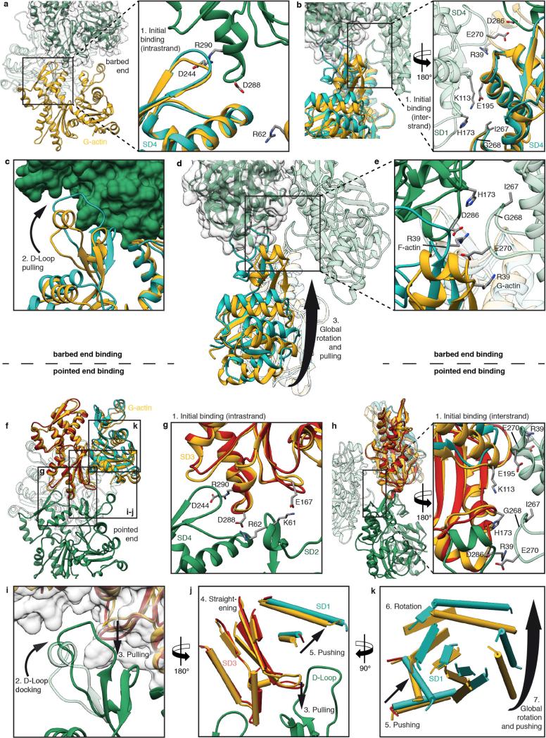
The comparison of the structures of F-actin with that of G-actin (PDB accession codes 3EL2 and 1J6Z), which represent the start and end points of filament formation, allows us to describe the possible conformational changes during polymerization (Extended Data Fig. 7, Supplementary Discussion).
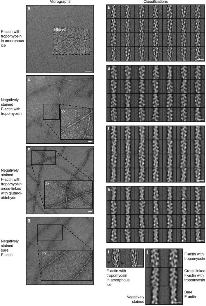
The F-actin filaments were completely decorated by tropomyosin (Fig. 1a, Extended Data Fig. 1a, b, i). Although tropomyosin consists of seven pseudo-repeating units, applying the helical symmetry of F-actin for the reconstruction of the F-actin–tropomyosin complex results in a reduced resolution of tropomyosin and the overlap region of the N and C termini is not visible in the map (see Methods). However, densities corresponding to the helices of the coiled-coil were well resolved (Fig. 1a, b) and allowed us to fit a previous chimeric model of tropomyosin derived from X-ray, nuclear magnetic resonance and molecular dynamics simulation data24 and to determine the register of the chains of tropomyosin. Together with the atomic resolution of F-actin, this allows us to describe the interaction between actin and tropomyosin in greater detail and with higher accuracy than previous studies.
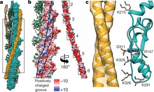
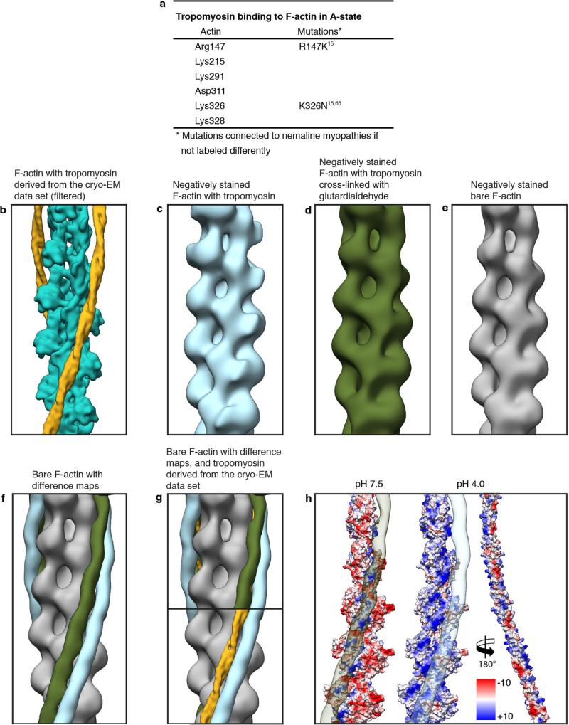
Tropomyosin, which is mainly negatively charged on its surface, interacts with a positively charged groove on F-actin, confirming previous predictions (Fig. 4a, b, Extended Data Fig. 8a). In particular, lysines 326 and 328 on F-actin strongly interact with the different pseudo-repeats of tropomyosin (Fig. 4c). The distance between tropomyosin and actin varies depending on the position along the filament between 38 Å and 40 Å. The distance would allow for direct interactions of opposing residues (Fig. 4c) and is similar to the distance in the M-state8 and to what was previously suggested for the other states of tropomyosin25,26. The interactions between tropomyosin and F-actin probably determine the position of tropomyosin on F-actin in the Apo-state (A-state), a term we recently introduced to describe the position of tropomyosin in the absence of troponin, myosin or Ca2+ (ref. 27).
Figure 4. F-actin interaction with tropomyosin.
a, Structural overview of an F-actin filament (green and cyan) decorated with tropomyosin (yellow). Half of the filament is shown in surface representation. The N and C termini of F-actin are included in this model. b, Surface of F-actin and tropomyosin (pseudo-repeats 2–6) with the electrostatic Coulomb potentials ranging from −10 kcal mol−1 to +10 kcal mol−1 at pH 7.5. Tropomyosin was rotated by 180° and shifted to the right to allow a better view on the F-actin–tropomyosin interface, which is delimited by lines drawn onto the surfaces. The overall negatively charged tropomyosin interacts with a positively charged groove on F-actin. c, Several charged residues of actin are within distances that would make it possible to interact with tropomyosin via putative salt bridges. Different rotamers (orientations of a residue) of the same residue are shown to indicate how F-actin subunits could adjust to the surfaces of different tropomyosin pseudo-repeats.
The position of tropomyosin in the A-state in our structure (Fig. 4a, Extended Data Fig. 8b) is close to that described by Sousa et al.13, but differs from a previous positioning based on negative stain data and molecular dynamics simulations24. To determine the source of this discrepancy, we first repeated the negative stain work (Extended Data Fig. 1c–j) and indeed reproduced the different position (Extended Data Fig. 8c). However, when we cross-linked the sample before staining, tropomyosin was in the same position as in our cryo-EM structure (Extended Data Fig. 1c–h, j, Extended Data Fig. 8d–g). This shows that negative staining rather than cryo-preparation (the sample is frozen quickly in liquid ethane without ice crystal formation) results in a change of the tropomyosin position on F-actin. The relatively low pH of the stain (pH 4) probably induces repulsions at the F-actin–tropomyosin interface and forces tropomyosin to change its position (Extended Data Fig. 8h). In any case, the change in position depending on preparative conditions confirms the striking ability of tropomyosin to translocate azimuthally across the actin filament at low energy cost27.
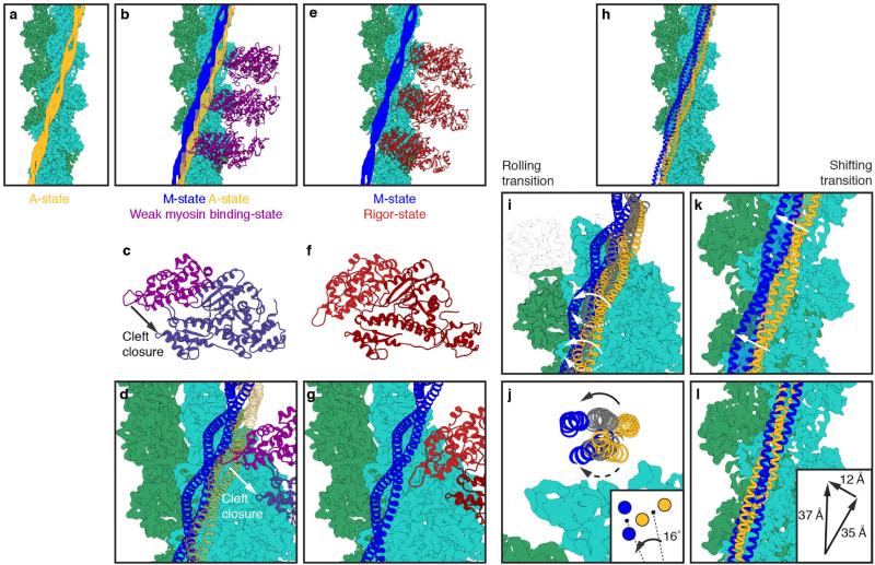
In comparison to the previously assumed position of tropomyosin in the A-state, the new position blocks only minor regions of the myosin-binding site. This supports our previous model of myosin binding to actin filaments in the absence of troponin8 even more strongly. If the current position of tropomyosin is the default state for tropomyosin, then only loop 4 and the cardiomyopathy loop of myosin would be sterically hindered from binding to the F-actin filament (Extended Data Fig. 9a–d, Supplementary Video 4) and probably allows for a weak binding of myosin, especially with its lower 50-kDa domain. Actin-induced cleft closure of myosin would then move tropomyosin to its M-state8 (Extended Data Fig. 9b–g, Supplementary Video 4).
Comparing the position of tropomyosin in the new A-state with the M-state(Extended Data Fig. 9h), we find two possible transitions between the states. Either tropomyosin rolls on the F-actin filament by an azimuthal rotation of about 16° and a left-handed rotation of about 70° or a right-handed rotation of about 110° along its own axis (Extended Data Fig. 9i, j) or tropomyosin shifts by about 37 Å (half the length of a pseudo-repeat) along the actin filament (Extended Data Fig. 9k, l) or a mixture of the two effects occurs. The distance of tropomyosin to the filament axis of F-actin is not altered during the transition. Gestalt-binding and rigidity of tropomyosin28 support a shifting mechanism, whereas the spatial limitations inside the sarcomere make a shift of 37 Å rather unlikely. However, direct localization of the N/C-terminal overlap of tropomyosin will be needed to discriminate between the two possibilities.
In summary, the structure of the F-actin-tropomyosin complex shows how F-actin filaments are stabilized in health and destabilized in certain diseases. Our results provide the structural framework for further experiments towards resolving the molecular details of actin polymerization and its interaction with actin-regulating proteins such as tropomyosin.
METHODS
Protein expression and purification
F-actin was isolated from rabbit skeletal muscle acetone powder and purified with several polymerization and depolymerization steps as described previously29. The composition of the G-actin buffer was 5 mM Tris pH 7.5, 1 mM DTT, 0.2 mM CaCl2. Recombinant α-tropomyosin (Mus musculus, alpha-1 chain, Uniprot-ID P58771) with an alanine-serine extension was purified from Escherichia coli, based on the protocol of ref. 30. The α-tropomyosin isoform we used is abundant in smooth and striated muscles. The actin–tropomyosin complex was prepared by mixing F-actin with tropomyosin initially at a molar ratio of 7:1 in filament buffer (5 mM Tris-HCl pH 7.5, 1 mM DTT, 100 mM KCl, and 2 mM MgCl2). The final concentration of tropomyosin for either negatively stained or frozen specimens was then adjusted empirically to obtain complete decoration and only few unbound tropomyosins in the background. For the cross-linking studies between F-actin and tropomyosin, samples were prepared in filament buffer containing 5 mM HEPES (pH 7.5).
Preparation for negative-stain electron microscopy
To stabilize and straighten the F-actin filaments (this is important for image processing), we decorated them with tropomyosin. Actin–tropomyosin complexes were directly prepared before the negative staining procedure. 4 μl of sample was applied on a freshly glow-discharged copper grid (Agar Scientific; G2400C) with an additional thin and continuous carbon film. After incubation for 60 s on the grid the sample was blotted using filter paper (Whatman no. 4), washed twice with filament buffer and stained with 0.75% uranyl formate (pH 4.0) for 30 s. For cross-linking studies, after incubation for 60 s of the sample solution on the grid and one washing step, a droplet of filament buffer with 0.25% glutardialdehyde was applied for 30 min on the grid before negative staining to avoid putative pH-induced artefacts. All images were taken with a JEOL JEM-1400 electron microscope equipped with a LaB6 cathode at an operation voltage of 120 kV. Micrographs were recorded manually with a 4,000 × 4,000 pixel complementary metal–oxide–semiconductor (CMOS) TemCam F416 (TVIPS) camera under minimal dose conditions.
Image processing of negatively stained filaments
All micrographs had a pixel size of 2.32 Å per pixel and filaments were boxed with a boxing distance of 13 pixels (overlap ~90%) and a total box size of 128 pixels. We analysed 8,371 segments from 40 images of bare F-actin, 27,926 segments from 111 images of F-actin decorated with tropomyosin, and 27,011 segments from 81 images of F-actin decorated with tropomyosin and cross-linked with glutardialdehyde. Subsequently, all segment stacks were aligned and classified independently using reference-free alignment and k-means classification procedures as implemented in SPARX31 (Extended Data Fig. 1c–h, j). During the helical refinement and reconstruction using the helicon package implemented in SPARX31, a cylinder filled with Gaussian noise was used as an initial three-dimensional template. The position of tropomyosin was determined in the resulting three-dimensional maps. The difference maps of tropomyosin–bare F-actin and glutardialdehyde–bare F-actin were calculated with the ‘vop subtract’ command in Chimera32 (Extended Data Fig. 8c–g).
Grid preparation and image acquisition for cryo-EM
A 1.5-μl sample was applied to a glow-discharged holey carbon grid (C-flats 2/1, Protochips), incubated for 10 s and manually blotted for 3 s from the backside with filter paper (Whatman no. 5), before vitrification by plunging the grid into liquid ethane using a Cp3 (Gatan). Screening for the best sample and blotting conditions was performed on a JEOL JEM 3200FSC electron microscope equipped with a field emission gun and operated at a voltage of 200 kV. The omega in-column energy filter of the microscope was used to estimate the best ice conditions (~40–60 nm thickness). Finally, a data set was taken with a spherical-aberration (Cs)-corrected FEI Titan Krios transmission electron microscope equipped with a X-field emission gun and operated at a voltage of 300 kV. Images were recorded with a back-thinned 4k × 4k FEI Falcon 2 direct detection camera under minimal dose conditions using the automatic data collection software EPU (FEI). Within each selected grid-hole, three different positions were imaged, each with a total exposure of 1 s and a frame time of 55 ms. Seven frames from 85 ms to 475 ms with a total dose of 14.6 electrons per Å2 and one total average with an electron dose of 30.7 electrons per Å2 were used for image processing. The defocus range of the data set was 0.8–2.6 μm. The pixel size was 1.14 Å per pixel, based on the reflection of gold at the same magnification. Since the inaccuracy of pixel size determination is about 2% with this method, we used the well-defined rise per subunit of F-actin (27.6 Å) from fibre diffraction studies14,33 instead to calibrate the pixel size, which was then 1.12 Å per pixel.
Image processing of the cryo-EM data set
As a first quality control, all 1,311 frame averages were manually inspected and only 689 images with high filament quality (Extended Data Fig. 1a) were used for further processing. Frames were aligned and afterwards summed up using motion correction34. Filaments were manually selected with helixboxer in SPARX. A total of 109,242 segments from 7,854 filaments were extracted with a box size of 256 pixels and a boxing distance of 29 pixels (overlap ~ 90%). Thus, the approximate distance between them (~32 Å) slightly exceeded the rise of the helical assembly of actin (~27–28 Å), as required by the helicon design. The defocus and astigmatism and the accuracy of both were determined by cter35 in SPARX. All segments were aligned and classified using reference-free alignment and k-means classification procedures implemented in SPARX (Extended Data Fig. 1b, i). For the initial reconstruction, the data set was binned twice to a pixel size of 2.24 Å and a box size of 128 pixels. We used a cylinder filled with Gaussian noise as a three-dimensional initial template for the helical refinement and reconstruction in the helicon. After adjusting the pixel size as described above, the helical symmetry parameters converged to a rise per subunit of 27.5 Å and an azimuthal rotation of 166.4°. Initially, the entire F-actin–tropomyosin map was used as the reference during the first rounds of refinement, using the helical symmetry parameters of F-actin. However, tropomyosin spans over seven actin subunits and therefore has a symmetry different to that of actin. Nevertheless, because it is divided into seven pseudo-repeating units, each of which binds to a successive actin subunit along F-actin, the symmetry of F-actin could be used for reconstructions of actin-tropomyosin complexes of up to 6 Å resolution, accepting that the overlap region of the N and C termini of tropomyosin would not be discernible in these maps. Once the refined map reached a resolution of 6.5 Å, as determined by the FSC0.5 criterion36, we masked out tropomyosin in the reference volume before continuing with high-resolution refinements of F-actin. In the last refinement iteration, we used only filaments derived from summed up frames with a drift of less than 7 Å, as estimated in the motion correction34 step and with a sufficient content of high-resolution information, as determined by cter35 in SPARX. This yielded a subset of 74,228 segments for the final map, which corresponded to ~120,000 asymmetric subunits. The segments’ statistics are given in Extended Data Table 1. Since an electron microscope map of a filament is truncated at the edges of the cubic volume of the box (here 2563 voxels), a mask with Gaussian edges must be applied for resolution estimation to minimize artefacts. Therefore, Fourier shell correlation (FSC) analysis was performed within the central area of the volume, resulting in a nominal resolution of 3.7 Å (FSC0.5 criterion36) for the F-actin electron density map (Extended Data Fig. 2a). The map of F-actin was then sharpened using a negative b factor of −50 Å2 and filtered to its nominal resolution. Finally, the tropomyosin map filtered to 6.5 Å was merged with the final F-actin map to obtain a map of the entire F-actin–tropomyosin complex.
We also tried to process tropomyosin separately from F-actin. After alignment of the filaments based on F-actin, we masked out tropomyosin. To find the N- or C-terminal overlap and guarantee the proper alignment of tropomyosin, we used very large boxes to allow tropomyosin to shift by almost its full length and tried to align the molecules. However, this approach did not work. We suspect that the pseudo-repeats and even the N/C-terminal overlaps are too similar to each other (at least in cryo-EM raw images), resulting in an improper alignment. We are therefore investigating labelling strategies to solve this problem.
Model building and refinement of F-actin
The central F-actin subunit (chain A) shows all available contacts to adjacent chains (B, C, D, E) and was therefore used for further structural analysis. In a first step, five central subunits (chains A–F) of an F-actin model (PDB accession code 4A7N; ref. 8) was rigid-body fitted into the electron microscope map, using ‘Fit in Map’ and the map was initially segmented with ‘Split Map’ in Chimera32,37. Homology modelling was performed using MODELLER38 and the resulting model of the central subunit was then flexibly fitted into its corresponding part of the density using DireX39. Finally, the flexibly fitted subunit was used to create a starting F-actin model of five adjacent subunits (hereafter referred to as the ‘pentamer’) for further model building. The electron density was converted to structure factors with the CCP4 program suite40. The model and the map were then used for real space refinement and model building in COOT41. After a single iteration of model building of the central F-actin subunit, its part of the map was further used for an initial automatic reciprocal space refinement using PHENIX.refine42. Since this part was less well resolved in the N terminus and the C terminus, and model building was difficult for a part of the D-loop, we deleted amino acids 1–4, 42–50 and 372–375 from the model. Owing to the high reliability of the experimental phases of the cryo-EM map, we were able to apply experimental phase restraints during refinement in PHENIX. After refinement the output model was again manually refined in COOT using the original cryo-EM map to minimize model bias. Rebuilding of the N or C terminus was not possible even in the refined map (Extended Data Fig. 2c, d). However, after refinement in PHENIX the definition of the D-loop improved, so ultimately it could be manually rebuilt ab initio.
After refinement of the subunit had converged and model building was completed, the resulting subunit was used to assemble the F-actin pentamer and the respective full map of the central pentamer was then segmented. The molecular model and the respective original density were then used as input for PHENIX.refine. Again, we alternated manual model building and refinement steps. Finally, the resulting model was validated using MOLPROBITY43 (see data statistics in Extended Data Table 1). For further structural analysis we used the final model and the cryo-EM map of the actin pentamer.
Structure analysis and visualization
To describe the interaction between F-actin and tropomyosin, a chimaeric molecular model of tropomyosin44 was initially rigid-body fitted into the cryo-EM density of F-actin–tropomyosin. Subsequently, the respective density of tropomyosin was extracted as described above using Chimera. The molecular model of tropomyosin was then flexibly fitted into the resulting density using DireX39. Furthermore, during flexible fitting, in order to preserve its electrostatically preferred position on F-actin we fixed tropomyosin in its vertical position on the filament. Atomic clashes and stereochemistry were repaired using PHENIX.geometry_minimization42. Since the tropomyosin N/C-terminal overlap is not fully understood45, we reduced the model to the five central pseudo-repeats. Owing to the limited resolution of the cryo-EM density in the region of tropomyosin, we avoided interpretation of tropomyosin on the single-amino-acid level.
We used the refined actin pentamer and the modelled tropomyosin to reconstruct a full filament for visualization of the actin–tropomyosin interaction (Fig. 3). The filament was protonated using H++46 at different pH values and the electrostatic coulomb potential of the filament surface was calculated to range from −10 kcal mol−1 to +10 kcal mol−1 in Chimera (Fig. 4b, Extended Data Fig. 8h). For visualization of the hydrophobicity per amino acid residue, we used ‘Define attribute’ in Chimera and generated amino-acid-specific scores47. Point mutations were introduced via COOT or Chimera to show charge-induced repulsions and changes in hydrophobicity. The HGMD48 library was browsed to find mutations in regions of interest.
For detailed analyses of intra- and intermolecular interactions in F-actin, we applied PISA tools49 and distance measurements in Chimera. The G- to F-actin transition within a monomer/subunit was visualized and interpreted with the ‘Morph Conformations’ in Chimera. Furthermore, the hinge region and the global rotation angle were detected with the DynDom Sever50 using an atomic model of G-actin (PDB accession code 1J6Z; ref. 51) and one subunit of our F-actin model (Fig. 3).
Extended Data
Extended Data Figure 1. Micrographs and classifications of different data sets.
a–h, Representative digital micrographs and corresponding representative two-dimensional class averages of F-actin decorated with tropomyosin in amorphous ice (in total 300 class averages of randomly chosen 40,000 phase-flipped segments of in total 109,242 segments from 689 images) (a, b), negatively stained (in total 300 class averages of 27,926 segments from 111 images) (c, d), negatively stained after cross-linking with glutardialdehyde (in total 300 class averages of 27,011 segments from 81 images) (e, f), and a micrograph of negatively stained bare F-actin (in total 100 class averages of 8,371 segments from 40 images) (g, h). Some areas of the micrographs are either filtered or enlarged, as indicated in the figures. Scale bars, 50 nm. Each class average (‘Classifications’) contains 130–200 (cryo data set) or 70–90 (negatively stained data sets) single segments. Scale bars, 10 nm. A boxed region of the digital micrograph in a was band-pass filtered to allow a better visualization of the filaments. Insets in c, e and g show 2× magnified regions of the digital micrographs. i, Two of the class averages depicted in b that show a clear tropomyosin density. The tropomyosin density is indicated by black arrows. Scale bar, 10 nm. j, Comparison of representative class averages of the three negative-stain data sets. Class averages of the data sets with tropomyosin (top panels) show additional density and a larger diameter than bare F-actin (bottom panel). Scale bar, 10 nm. 8,371 segments from 40 images of bare F-actin, 27,926 segments from 111 images of F-actin decorated with tropomyosin, and 27,011 segments from 81 images of F-actin decorated with tropomyosin and cross-linked with glutardialdehyde.
Extended Data Figure 2. Resolution of the F-actin–tropomyosin complex.
a, FSC curves of different areas of interest by masking (see Methods). The resolution of tropomyosin was estimated using the twice down-sampled data set (2.24 Å per pixel). The FSC0.5 criterion indicates that the tropomyosin electron density map has a resolution of 6.5 Å. The resolution of the final F-actin electron density map is estimated at a resolution of 3.7 Å (FSC0.5). b, Surfaces of F-actin with B-factors (high is red, low is blue; the B-factor indicates the true static or dynamic mobility of an atom) estimated by the reciprocal space refinement in PHENIX42. A side view as well as top views on the inward- and outward-facing surfaces, that is, facing the adjacent F-actin subunit inside the filament and oriented to the periphery, respectively, are shown. c, d, Putative structures of the C and N termini (cyan), respectively. Electron density is missing in these regions.
Extended Data Figure 3. Representative regions of the F-actin electron density map.
a, Overview of the atomic model of an F-actin subunit rainbow-coloured from the N terminus (blue) to the C terminus (red). ADP and the coordinated cation, probably Mg2+, are depicted inside their corresponding electron densities. b–d, Side view. Interface between the D-loop (SD2) and the SD3 of the adjacent actin subunit (b), outer two helices of SD1 (c), and inner β-sheet with N terminus (d). e, f, Front view. Connection of SD1 and SD3 (e) and nucleotide binding cleft (f). g, h, Side view. Inner β-sheet of SD3 with one highlighted strand (g) and outer part of SD3 (h). i, j, Back view. SD4 separated in two parts.
Extended Data Figure 4. Overview of inter- and intrastrand interactions and hydrophobic D-loop.
a, Table of identified residues that are involved in intra- and intermolecular interactions and known mutations. b, Overview of the D-loop bound to the hydrophobic cleft in SD3 of the F-actin molecule on top. Surfaces and residues are coloured from high (yellow) to low (white) hydrophobicity. c, Involved hydrophobic residues of the D-loop. d, e, Modifications in the D-loop, like oxidation of methionine 44 (ref. 20) (c) or mutations of methionine 44 and glycine 46 (M44T, G46G)15,20 (d) change the polarity or insert charges and consequently weaken the hydrophobic interactions. Thus, this destabilization of the intrastrand contact is connected to anomalous actin filament assembly and nemaline myopathies3,15,20,52–58.
Extended Data Figure 5. Interstrand and intrastrand F-actin interactions.
a–e, The interface at the plug involves three residues (R39, E270, D286) that form salt bridges and mediate not only one interstrand contact but also one intrastrand contact. In addition, the orientation of residues 264–269 result in a negatively charged patch that electrostatically interacts with positively charged residues on the opposing actin. a, b, Front and back view of the interface at the plug, respectively. c–e, Surface representations (front views in c and d, back view in e) depicting the Coulomb potential, indicating that the interaction of the upper region of the plug with adjacent inter- or intrastrand molecules is mediated by electrostatic interactions. f, Another interstrand contact is formed by residues 110–115 of SD1 and residues 191–199 of SD4 of the adjacent actin. However, no prominent electrostatic or hydrophobic interactions could be identified at this interface.
Extended Data Figure 6. Nucleotide binding site and intramolecular interactions.
a, Table of identified intramolecular interactions that result in a stabilization of the nucleotide binding cleft, coordination of ADP and a divalent cation. Data are from refs 3, 15, 23, 53, 54, 56, 57 and 60–64. b, Coordination of ADP and Ca2+ in the nucleotide binding cleft in G-actin (PDB accession code 3EL2; ref. 59). c–e, Back view of the nucleotide binding cleft of F-actin (cyan) with bound ADP–Mg2+ or ADP–Ca2+ (c), ATP–Ca2+ (d, relative position taken from PDB accession code 3EL2; ref. 59) and conformational changes between the G-actin-ATP and F-actin-ADP state (e). Glutamine 137 is moved closer to ADP, coordinating not only the cation (as in G-actin) but also the nucleotide β-phosphate (c). The presence of ATP instead of ADP in the nucleotide-binding site would be sterically unfavourable, suggesting that a different intermediate conformation exists for F-actin-ATP (d). The shorter distance of glutamine 137 to the γ-phosphate probably induces ATP hydrolysis and then afterwards the cation takes the position of the γ-phosphate in the ADP-state (e). For comparison the position of glutamine 137 in G-actin is shown in yellow and the transition from G-actin to F-actin is depicted by arrows. f, Mutation of glutamine 137 to histidine results in hampered coordination of the ion and the nucleotide and is connected to nemaline myopathies23.
Extended Data Figure 7. Model of barbed-end and pointed-end binding and G- to F-actin transition based on a comparison of start point (G-actin) and end point (F-actin).
a, b, Binding of new G-actin (yellow, PDB accession code 3EL2; ref. 59) at the barbed end of F-actin (green) is initiated by the intrastrand binding of SD4 of G-actin to SD3 of F-actin (a, side view) and the interstrand binding of SD4 and SD1 (b, front view), respectively. G-actin is overlaid with a subunit of the structure found in F-actin (cyan). The main interstrand contacts are already present at the start of the transition and thereby guide the binding G-actin to its correct position, determining the symmetry of the filament. c, After initial binding the D-loop is trapped in the hydrophobic cleft of SD3 of F-actin and pulls on SD2. F-actin is depicted in surface representation (green). d, Finally, the SD2 and concomitantly SD1 are rotated and the final F-actin conformation is stabilized by various intramolecular interactions (see Figs 2c–f and 3c–f, Extended Data Fig. 6a). e, Owing to the relatively large distance from the SD1 and SD2 subdomains of the newly bound G-actin to the subunit of the opposite strand, the only influence of the opposite strand on the binding of G-actin is at the docking position of the D-loop. The transition of R39 illustrates well the docking of the D-loop. The residue is depicted in both states (G-actin and F-actin). f–h, Binding of new G-actin (yellow, PDB accession code 3EL2; ref. 59) at the pointed end of F-actin (green) is initiated by initial intrastrand binding (g) of SD3 of G-actin to SD4 of F-actin at the pointed end and interstrand binding of SD4 to SD3 (h), respectively. Again, the main interstrand contacts are available before the transition of G-actin (yellow) to F-actin (SD1 and SD2 in cyan, SD3 and SD4 are red). i, During binding to F-actin the transition from G-actin to F-actin is initiated by an induced fit of the F-actin D-loop to the hydrophobic cleft of the newly bound G-actin. This leads to a pulling down of the central β-sheet of SD3 of G-actin. j, The β-sheet is thereby straightened and pushes up two adjacent helices of SD1. k, The slight dislocation of these helices is transmitted to other regions of SD1 and thereby emphasized. This leads to a global rotation of SD1, which results in a considerable rotation of SD2 by an angle of 20° and a closure of the nucleotide binding cleft (Fig. 3; see Supplementary Video 3).
Extended Data Figure 8. Tropomyosin binding and comparison of reconstructions regarding the tropomyosin position on F-actin.
a, Table showing putative residues of F-actin involved in tropomyosin binding and known mutations. b–e, Reconstructions of F-actin decorated with tropomyosin calculated from: the cryo-EM data set filtered to 15 Å (b), from a negatively stained data set (c), from a negatively stained data set after cross-linking with glutardialdehyde (d), and from negatively stained bare F-actin (e). f, By calculating a difference map between tropomyosin–bare F-actin (blue) and glutardialdehyde–bare F-actin (green), differences in the tropomyosin position on bare F-actin (grey) are visualized. g, Overlay of difference maps showing that the position of tropomyosin in the cryo-EM reconstruction (yellow) corresponds to the tropomyosin position of the negatively stained data set with the cross-linked complex (green). h, Surface of F-actin and tropomyosin (pseudo-repeats 2–6) with the electrostatic Coulomb potentials at pH 7.5 and pH 4 (see also Fig. 4b). Tropomyosin was rotated by 180° and shifted to the right to allow a better view of the F-actin–tropomyosin interface. Difference maps of the glutardialdehyde–bare F-actin and the tropomyosin–bare F-actin map are shown on the F-actin surface at pH 7.5 (left) and pH 4.0 (middle), respectively15,65.
Extended Data Figure 9. Model of tropomyosin transition on F-actin during myosin binding.
a, Cryo-EM structure of the F-actin–tropomyosin complex with tropomyosin in the A-state. Tropomyosin (yellow, A-state), F-actin (green). b–d, Initial weak binding of myosin (magenta, PDB accession code 1LKX; ref. 66) to the F-actin–tropomyosin filament in the absence of troponin. Most of the myosin binding sites on F-actin are not occupied by tropomyosin and only loop 4 and the cardiomyopathy loop are sterically hindered from binding to the F-actin filament (b). Actin-induced closure of the 50 kDa cleft of myosin (c) results in a strong binding of myosin and tropomyosin moves to its M-state position (blue) (d). e–g, Actin–tropomyosin–myosin complex in the rigor state (PDB accession code 4A7H; ref. 8). Myosin is shown in red. h–l, There are two possible ways for the transition of tropomyosin from the A-state to the M-state. Tropomyosin either rolls (i, j) or slides (k, l) from one to the other position. Rolling would involve an azimuthal rotation of ~16° with respect to the F-actin axis (inset of j) and a left-handed rotation of ~70° (indicated by solid arrows) or a right-handed rotation of ~110° (indicated by dotted arrows) with respect to its own axis (i, j). Sliding would imply not only an azimuthal shift of ~12 Å (indicated by white arrows in k), but also a tremendous shift of a half-tropomyosin repeat (that is, ~35 Å) along the F-actin filament (k, l). The radius to the filament axis would be preserved in both situations. The inset of l depicts the vectors for a shifting transition of tropomyosin: an azimuthal and longitudinal shift of 12 Å and 35 Å, resulting in an overall shift of 37 Å.
Extended Data Table 1.
Data collection and refinement statistics
| Data collection | ||
| Magnification | ×122,270 | |
| Defocus range (μm) | 0.8-2.6 | |
| Voltage (kV) | 300 | |
| Mircoscope | Titan Krios (Cs corrected) | |
| Camera | Falcon 2 (4k DED) | |
| Frame recording time (s) | 0.085-0.475 | |
| Number of frames | 7 | |
| Electron dose (e−Å−2) | 14.6 | |
| Pixel size (Å) | 1.12 | |
| Particle statistics | ||
| Filaments* | 7,854 (5,239) | |
| Box size (px) | 256 | |
| Boxing distance (px) | 29 | |
| Rise (Å) | 27.5 | |
| Azimuthal rotation (°) | 166.4 | |
| Segments* | 109,242 (74,228) | |
| Asymmetric subunits* | ~180,000 (~120,000) | |

|

|
||
|---|---|---|---|
| Model composition | Chain ID | ABCDE | A |
| Non-hydrogen atoms | 14,450 | 2,890 | |
| Protein residues | 1,835 | 367 | |
| Ligand (ADP Mg2+) | 140 | 28 | |
| Refinement | |||
| Resolution used for refinement (Å) | 95.2-3.7 | ||
| Map sharpening B-factor (Å2) | −50 | ||
| Average B factor (Å2) | 55.40 | 53.40 | |
| R factor† | 0.277 | ||
| Cross-Resolution function‡ | 0.81 | 0.83 | |
| Rms deviations | |||
| Bonds (Å) | 0.004 | 0.005 | |
| Angles (°) | 1.10 | 1.12 | |
| Validation | |||
| Clashscore, all atoms | 19.99 | 18.32 | |
| Poor rotamers (%) | 1.23 | 1.29 | |
| Ramachandran plot | |||
| Favored (%) | 87.20 | 87.40 | |
| Outliers (%) | 1.37 | 1.37 | |
Number in parentheses is count after sorting the dataset regarding micrograph quality
R factor = Σ|Fobs|-|Fcalc| / Σ|Fobs|
FCRoverall = Σ(Nshell FSCshell) / ΣNshell, with Nshell as number of ‘structure factors’ in given shell and FSCshell = Σ(Fmodel FEM) / √(Σ|Fmodel|2 Σ|FEM|2)
Refinement statistics are shown after the last step of the refinement of the F-actin pentamer. In addition, relevant values of the central chain A are shown. Rms, root mean squared.
Supplementary Material
Acknowledgements
We thank O. Hofnagel for excellent assistance in cryo sample preparation and electron microscopy, R. S. Goody for continuous support and for comments on the manuscript and I. Vetter for assistance in data processing. We gratefully acknowledge R. Matadeen and S. de Carlo (FEI Company) for image acquisition at the National Center for Electron Nanoscopy in Leiden (NeCEN), which is co-financed by grants from the Nederlandse Organisatie voor Wetenschappelijk Onderzoek (project 175.010.2009.001) and by the European Union's Regional Development Fund through ‘Kansen voor West’ (project 21Z.014). J.v.d.E. is a fellow of Studienstiftung des deutschen Volkes. This work was supported by the Behrens-Weise foundation (to S.R.), NIH U54 094598 and R01 60635 (to P.A.P.) and R37HL036153 (to W.L.).
Footnotes
Author Contributions J.v.d.E. and S.R. designed the project. M.M. and D.J.M. provided protein samples. W.L. and D.J.M. provided information on tropomyosin and actin. J.v.d.E. performed research, analysed the data, and prepared figures. J.v.d.E. and P.A.P. improved image processing of helical specimens. S.R. managed the project and wrote the manuscript. All authors discussed the results and commented on the manuscript.
Author Information The coordinates for the electron microscope structure has been deposited in the Electron Microscopy Data Bank under accession code EMD-6124. Coordinates of F-actin in complex with tropomyosin have been deposited in the Protein Data Bank with accession number 3J8A. The authors declare no competing financial interests. Readers are welcome to comment on the online version of the paper.
Online Content Methods, along with any additional Extended Data display items and Source Data, are available in the online version of the paper; references unique to these sections appear only in the online paper.
Supplementary Information is available in the online version of the paper.
References
- 1.van Wijk E, et al. A mutation in the gamma actin 1 (ACTG1) gene causes autosomal dominant hearing loss (DFNA20/26). J. Med. Genet. 2003;40:879–884. doi: 10.1136/jmg.40.12.879. [DOI] [PMC free article] [PubMed] [Google Scholar]
- 2.Milewicz DM, et al. Genetic basis of thoracic aortic aneurysms and dissections: focus on smooth muscle cell contractile dysfunction. Annu. Rev. Genomics Hum. Genet. 2008;9:283–302. doi: 10.1146/annurev.genom.8.080706.092303. [DOI] [PubMed] [Google Scholar]
- 3.Sparrow JC, et al. Muscle disease caused by mutations in the skeletal muscle alpha-actin gene (ACTA1). Neuromuscul. Disord. 2003;13:519–531. doi: 10.1016/s0960-8966(03)00101-9. [DOI] [PubMed] [Google Scholar]
- 4.Gordon AM, Homsher E, Regnier M. Regulation of contraction in striated muscle. Physiol. Rev. 2000;80:853–924. doi: 10.1152/physrev.2000.80.2.853. [DOI] [PubMed] [Google Scholar]
- 5.Maytum R, Lehrer SS, Geeves MA. Cooperativity and switching within the three-state model of muscle regulation. Biochemistry. 1999;38:1102–1110. doi: 10.1021/bi981603e. [DOI] [PubMed] [Google Scholar]
- 6.Pittenger MF, Kazzaz JA, Helfman DM. Functional properties of non-muscle tropomyosin isoforms. Curr. Opin. Cell Biol. 1994;6:96–104. doi: 10.1016/0955-0674(94)90122-8. [DOI] [PubMed] [Google Scholar]
- 7.Kabsch W, Mannherz HG, Suck D, Pai EF, Holmes KC. Atomic structure of the actin:DNase I complex. Nature. 1990;347:37–44. doi: 10.1038/347037a0. [DOI] [PubMed] [Google Scholar]
- 8.Behrmann E, et al. Structure of the rigor actin-tropomyosin-myosin complex. Cell. 2012;150:327–338. doi: 10.1016/j.cell.2012.05.037. [DOI] [PMC free article] [PubMed] [Google Scholar]
- 9.Holmes KC, Popp D, Gebhard W, Kabsch W. Atomic model of the actin filament. Nature. 1990;347:44–49. doi: 10.1038/347044a0. [DOI] [PubMed] [Google Scholar]
- 10.Fujii T, Iwane AH, Yanagida T, Namba K. Direct visualization of secondary structures of F-actin by electron cryomicroscopy. Nature. 2010;467:724–728. doi: 10.1038/nature09372. [DOI] [PubMed] [Google Scholar]
- 11.Murakami K, et al. Structural basis for actin assembly, activation of ATP hydrolysis, and delayed phosphate release. Cell. 2010;143:275–287. doi: 10.1016/j.cell.2010.09.034. [DOI] [PubMed] [Google Scholar]
- 12.Galkin VE, Orlova A, Schröder GF, Egelman EH. Structural polymorphism in F-actin. Nature Struct. Mol. Biol. 2010;17:1318–1323. doi: 10.1038/nsmb.1930. [DOI] [PMC free article] [PubMed] [Google Scholar]
- 13.Sousa DR, Stagg SM, Stroupe ME. Cryo-EM structures of the actin:tropomyosin filament reveal the mechanism for the transition from C- to M-state. J. Mol. Biol. 2013;425:4544–4555. doi: 10.1016/j.jmb.2013.08.020. [DOI] [PMC free article] [PubMed] [Google Scholar]
- 14.Oda T, Iwasa M, Aihara T, Maéda Y, Narita A. The nature of the globular- to fibrous-actin transition. Nature. 2009;457:441–445. doi: 10.1038/nature07685. [DOI] [PubMed] [Google Scholar]
- 15.Laing NG, et al. Mutations and polymorphisms of the skeletal muscle alpha-actin gene (ACTA1). Hum. Mutat. 2009;30:1267–1277. doi: 10.1002/humu.21059. [DOI] [PMC free article] [PubMed] [Google Scholar]
- 16.Oztug Durer ZA, Diraviyam K, Sept D, Kudryashov DS, Reisler E. F-actin structure destabilization and DNase I binding loop fluctuations: mutational cross-linking and electron microscopy analysis of loop states and effects on F-actin. J. Mol. Biol. 2010;395:544–557. doi: 10.1016/j.jmb.2009.11.001. [DOI] [PMC free article] [PubMed] [Google Scholar]
- 17.Strzelecka-Gołaszewska H, Mossakowska M, Woźniak A, Moraczewska J, Nakayama H. Long-range conformational effects of proteolytic removal of the last three residues of actin. Biochem. J. 1995;307:527–534. doi: 10.1042/bj3070527. [DOI] [PMC free article] [PubMed] [Google Scholar]
- 18.Crosbie RH, et al. Structural connectivity in actin: effect of C-terminal modifications on the properties of actin. Biophys. J. 1994;67:1957–1964. doi: 10.1016/S0006-3495(94)80678-2. [DOI] [PMC free article] [PubMed] [Google Scholar]
- 19.Hung R-J, et al. Mical links semaphorins to F-actin disassembly. Nature. 2010;463:823–827. doi: 10.1038/nature08724. [DOI] [PMC free article] [PubMed] [Google Scholar]
- 20.Hung R-J, Pak CW, Terman JR. Direct redox regulation of F-actin assembly and disassembly by Mical. Science. 2011;334:1710–1713. doi: 10.1126/science.1211956. [DOI] [PMC free article] [PubMed] [Google Scholar]
- 21.Iwasa M, Maeda K, Narita A, Maéda Y, Oda T. Dual roles of Gln137 of actin revealed by recombinant human cardiac muscle alpha-actin mutants. J. Biol. Chem. 2008;283:21045–21053. doi: 10.1074/jbc.M800570200. [DOI] [PMC free article] [PubMed] [Google Scholar]
- 22.Vorobiev S, et al. The structure of nonvertebrate actin: implications for the ATP hydrolytic mechanism. Proc. Natl Acad. Sci. USA. 2003;100:5760–5765. doi: 10.1073/pnas.0832273100. [DOI] [PMC free article] [PubMed] [Google Scholar]
- 23.Koy A, et al. Nemaline myopathy with exclusively intranuclear rods and a novel mutation in ACTA1 (Q139H) Neuropediatrics. 2007;38:282–286. doi: 10.1055/s-2008-1065356. [DOI] [PubMed] [Google Scholar]
- 24.Li XE, et al. Tropomyosin position on F-actin revealed by EM reconstruction and computational chemistry. Biophys. J. 2011;100:1005–1013. doi: 10.1016/j.bpj.2010.12.3697. [DOI] [PMC free article] [PubMed] [Google Scholar]
- 25.Lorenz M, Poole KJ, Popp D, Rosenbaum G, Holmes KC. An atomic model of the unregulated thin filament obtained by X-ray fiber diffraction on oriented actintropomyosin gels. J. Mol. Biol. 1995;246:108–119. doi: 10.1006/jmbi.1994.0070. [DOI] [PubMed] [Google Scholar]
- 26.Poole KJV, et al. A comparison of muscle thin filament models obtained from electron microscopy reconstructions and low-angle X-ray fibre diagrams from non-overlap muscle. J. Struct. Biol. 2006;155:273–284. doi: 10.1016/j.jsb.2006.02.020. [DOI] [PubMed] [Google Scholar]
- 27.Lehman W, Orzechowski M, Li XE, Fischer S, Raunser S. Gestalt-binding of tropomyosin on actin during thin filament activation. J. Muscle Res. Cell Motil. 2013;34:155–163. doi: 10.1007/s10974-013-9342-0. [DOI] [PMC free article] [PubMed] [Google Scholar]
- 28.Holmes KC, Lehman W. Gestalt-binding of tropomyosin to actin filaments. J. Muscle Res. Cell Motil. 2008;29:213–219. doi: 10.1007/s10974-008-9157-6. [DOI] [PubMed] [Google Scholar]
- 29.Pardee JD, Spudich JA. Purification of muscle actin. Methods Enzymol. 1982;85B:164–181. doi: 10.1016/0076-6879(82)85020-9. [DOI] [PubMed] [Google Scholar]
- 30.Coulton A, Lehrer SS, Geeves MA. Functional homodimers and heterodimers of recombinant smooth muscle tropomyosin. Biochemistry. 2006;45:12853–12858. doi: 10.1021/bi0613224. [DOI] [PMC free article] [PubMed] [Google Scholar]
- 31.Hohn M, et al. SPARX, a new environment for Cryo-EM image processing. J. Struct. Biol. 2007;157:47–55. doi: 10.1016/j.jsb.2006.07.003. [DOI] [PubMed] [Google Scholar]
- 32.Pettersen EF, et al. UCSF Chimera—a visualization system for exploratory research and analysis. J. Comput. Chem. 2004;25:1605–1612. doi: 10.1002/jcc.20084. [DOI] [PubMed] [Google Scholar]
- 33.Dominguez R, Holmes KC. Actin structure and function. Annu. Rev. Biophys. 2011;40:169–186. doi: 10.1146/annurev-biophys-042910-155359. [DOI] [PMC free article] [PubMed] [Google Scholar]
- 34.Li X, et al. Electron counting and beam-induced motion correction enable near-atomic-resolution single-particle cryo-EM. Nature Methods. 2013;10:584–590. doi: 10.1038/nmeth.2472. [DOI] [PMC free article] [PubMed] [Google Scholar]
- 35.Penczek PA, et al. CTER-rapid estimation of CTF parameters with error assessment. Ultramicroscopy. 2014;140:9–19. doi: 10.1016/j.ultramic.2014.01.009. [DOI] [PMC free article] [PubMed] [Google Scholar]
- 36.Penczek PA. Resolution measures in molecular electron microscopy. Methods Enzymol. 2010;482:73–100. doi: 10.1016/S0076-6879(10)82003-8. [DOI] [PMC free article] [PubMed] [Google Scholar]
- 37.Pintilie GD, Zhang J, Goddard TD, Chiu W, Gossard DC. Quantitative analysis of cryo-EM density map segmentation by watershed and scale-space filtering, and fitting of structures by alignment to regions. J. Struct. Biol. 2010;170:427–438. doi: 10.1016/j.jsb.2010.03.007. [DOI] [PMC free article] [PubMed] [Google Scholar]
- 38.Šali A, Blundell TL. Comparative protein modelling by satisfaction of spatial restraints. J. Mol. Biol. 1993;234:779–815. doi: 10.1006/jmbi.1993.1626. [DOI] [PubMed] [Google Scholar]
- 39.Wang Z, Schröder GF. Real-space refinement with DireX: from global fitting to side-chain improvements. Biopolymers. 2012;97:687–697. doi: 10.1002/bip.22046. [DOI] [PubMed] [Google Scholar]
- 40.Winn MD, et al. Overview of the CCP4 suite and current developments. Acta Crystallogr. D Biol. Crystallogr. 2011;67:235–242. doi: 10.1107/S0907444910045749. [DOI] [PMC free article] [PubMed] [Google Scholar]
- 41.Emsley P, Lohkamp B, Scott WG, Cowtan K. Features and development of Coot. Acta Crystallogr. D Biol. Crystallogr. 2010;66:486–501. doi: 10.1107/S0907444910007493. [DOI] [PMC free article] [PubMed] [Google Scholar]
- 42.Adams PD, et al. The Phenix software for automated determination of macromolecular structures. Methods. 2011;55:94–106. doi: 10.1016/j.ymeth.2011.07.005. [DOI] [PMC free article] [PubMed] [Google Scholar]
- 43.Chen VB, et al. MolProbity: all-atom structure validation for macromolecular crystallography. Acta Crystallogr. D Biol. Crystallogr. 2010;66:12–21. doi: 10.1107/S0907444909042073. [DOI] [PMC free article] [PubMed] [Google Scholar]
- 44.Li XE, Orzechowski M, Lehman W, Fischer S. Structure and flexibility of the tropomyosin overlap junction. Biochem. Biophys. Res. Commun. 2014;446:304–308. doi: 10.1016/j.bbrc.2014.02.097. [DOI] [PMC free article] [PubMed] [Google Scholar]
- 45.Lehman W, Li XE, Orzechowski M, Fischer S. The structural dynamics of a-tropomyosin on F-actin shape the overlap complex between adjacent tropomyosin molecules. Arch. Biochem. Biophys. 2014;552–553:68–73. doi: 10.1016/j.abb.2013.09.011. [DOI] [PMC free article] [PubMed] [Google Scholar]
- 46.Anandakrishnan A, Aguilar B, Onufriev AV. H+ + 3.0: automating pK prediction and the preparation of biomolecular structures for atomistic molecular modeling and simulations. Nucleic Acids Res. 2012;40:W537–W541. doi: 10.1093/nar/gks375. [DOI] [PMC free article] [PubMed] [Google Scholar]
- 47.Hessa T, et al. Recognition of transmembrane helices by the endoplasmic reticulum translocon. Nature. 2005;433:377–381. doi: 10.1038/nature03216. [DOI] [PubMed] [Google Scholar]
- 48.Stenson PD, et al. The Human Gene Mutation Database: building a comprehensive mutation repositoryfor clinical and molecular genetics, diagnostic testing and personalized genomic medicine. Hum. Genet. 2014;133:1–9. doi: 10.1007/s00439-013-1358-4. [DOI] [PMC free article] [PubMed] [Google Scholar]
- 49.Krissinel E, Henrick K. Inference of macromolecular assemblies from crystalline state. J. Mol. Biol. 2007;372:774–797. doi: 10.1016/j.jmb.2007.05.022. [DOI] [PubMed] [Google Scholar]
- 50.Hayward S, Lee RA. Improvements in the analysis of domain motions in proteins from conformational change: DynDom version 1.50. J. Mol. Graph. Model. 2002;21:181–183. doi: 10.1016/s1093-3263(02)00140-7. [DOI] [PubMed] [Google Scholar]
- 51.Otterbein LR, Graceffa P, Dominguez R. The crystal structure of uncomplexed actin in the ADP state. Science. 2001;293:708–711. doi: 10.1126/science.1059700. [DOI] [PubMed] [Google Scholar]
- 52.Bathe FS, Rommelaere H, Machesky LM. Phenotypes of myopathy-related actin mutants in differentiated C2C12 myotubes. BMC Cell Biol. 2007;8:2. doi: 10.1186/1471-2121-8-2. [DOI] [PMC free article] [PubMed] [Google Scholar]
- 53.Costa CF, et al. Myopathy mutations in alpha-skeletal-muscle actin cause a range of molecular defects. J. Cell Sci. 2004;117:3367–3377. doi: 10.1242/jcs.01172. [DOI] [PubMed] [Google Scholar]
- 54.Nowak KJ, et al. Mutations in the skeletal muscle alpha-actin gene in patients with actin myopathy and nemaline myopathy. Nature Genet. 1999;23:208–212. doi: 10.1038/13837. [DOI] [PubMed] [Google Scholar]
- 55.Ohlsson M, Tajsharghi H, Darin N, Kyllerman M, Oldfors A. Follow-up of nemaline myopathy in two patients with novel mutations in the skeletal muscle alpha-actin gene (ACTA1). Neuromuscul. Disord. 2004;14:471–475. doi: 10.1016/j.nmd.2004.05.016. [DOI] [PubMed] [Google Scholar]
- 56.Ilkovski B, et al. Evidence for a dominant-negative effect in ACTA1 nemaline myopathy caused by abnormal folding, aggregation and altered polymerization of mutant actin isoforms. Hum. Mol. Genet. 2004;13:1727–1743. doi: 10.1093/hmg/ddh185. [DOI] [PubMed] [Google Scholar]
- 57.Graziano C, Bertini E, Minetti C, Porfirio B. Alpha-actin gene mutations and polymorphisms in Italian patients with nemaline myopathy. Int. J. Mol. Med. 2004;13:805–809. [PubMed] [Google Scholar]
- 58.Perkins KZ, et al. P3.48 Exome sequencing with linkage analysis identifies a novel ACTA1 variant in a large family with progressive muscle weakness. Neuromuscul. Disord. 2011;21:696–697. [Google Scholar]
- 59.Nair UB, et al. Crystal structures of monomeric actin bound to cytochalasin D. J. Mol. Biol. 2008;384:848–864. doi: 10.1016/j.jmb.2008.09.082. [DOI] [PMC free article] [PubMed] [Google Scholar]
- 60.Sudo A, et al. Sibling cases of severe infantile form of nemaline myopathy with ACTA1-gene mutation. [in Japanese] No To Hattatsu. 2013;45:452–456. [PubMed] [Google Scholar]
- 61.Yao X, Grade S, Wriggers W, Rubenstein PA. His(73), often methylated, is an important structural determinant for actin. A mutagenic analysis of HIS(73) of yeast actin. J. Biol. Chem. 1999;274:37443–37449. doi: 10.1074/jbc.274.52.37443. [DOI] [PubMed] [Google Scholar]
- 62.Agrawal PB, et al. Heterogeneity of nemaline myopathy cases with skeletal muscle alpha-actin gene mutations. Ann. Neurol. 2004;56:86–96. doi: 10.1002/ana.20157. [DOI] [PubMed] [Google Scholar]
- 63.D'Amico A, et al. Fatal hypertrophic cardiomyopathy and nemaline myopathy associated with ACTA1 K336E mutation. Neuromuscul. Disord. 2006;16:548–552. doi: 10.1016/j.nmd.2006.07.005. [DOI] [PubMed] [Google Scholar]
- 64.Stenzel W, et al. Fetal akinesia caused by a novel actin filament aggregate myopathy skeletal muscle actin gene (ACTA1) mutation. Neuromuscul. Disord. 2010;20:531–533. doi: 10.1016/j.nmd.2010.06.008. [DOI] [PubMed] [Google Scholar]
- 65.Jain RK, et al. Nemaline myopathy with stiffness and hypertonia associated with an ACTA1 mutation. Neurology. 2012;78:1100–1103. doi: 10.1212/WNL.0b013e31824e8ebe. [DOI] [PubMed] [Google Scholar]
- 66.Kollmar M, Dürrwang U, Kliche W, Manstein DJ, Kull FJ. Crystal structure of the motor domain of a class-I myosin. EMBO J. 2002;21:2517–2525. doi: 10.1093/emboj/21.11.2517. [DOI] [PMC free article] [PubMed] [Google Scholar]
Associated Data
This section collects any data citations, data availability statements, or supplementary materials included in this article.


