Abstract
This paper reports the design, fabrication, and characterization of a miniature high-frequency kerfless phased array prepared from a PMN-PT single crystal for forward-looking intravascular or endoscopic imaging applications. After lapping down to around 40 μm, the PMN-PT material was utilized to fabricate 32-element kerfless phased arrays using micromachining techniques. The aperture size of the active area was only 1.0 × 1.0 mm. The measured results showed that the array had a center frequency of 40 MHz, a bandwidth of 34% at −6 dB with a polymer matching layer, and an insertion loss of 20 dB at the center frequency. Phantom images were acquired and compared with simulated images. The results suggest that the feasibility of developing a phased array mounted at the tip of a forward-looking intravascular catheter or endoscope. The fabricated array exhibits much higher sensitivity than PZT ceramic-based arrays and demonstrates that PMN-PT is well suited for this application.
I. Introduction
Intravascular ultrasound (IVUS), using a specially designed catheter with a miniaturized ultrasonic transducer attached to the distal end of the catheter, has found many clinical applications, including diagnosing arterial diseases, guiding intervention such as stent deployment, and monitoring ablation procedures. Similarly, endoscopic ultrasound (EUS) is a medical procedure that uses an endoscope with an ultrasound probe attached to create detailed pictures of the digestive tract as well as surrounding tissues and organs. Currently, high-frequency (>10 MHz) ultrasound has extensively been used in EUS and IVUS imaging applications [1]–[5]. At present, single-element-transducer-based side-looking (SL) IVUS catheters are commercially available for use in the 20-MHz to 40-MHz frequency range. These probes provide high-resolution cross-sectional images of the vessel. However, because mechanical scanning is required for the single-element transducers, motion-induced artifacts may affect image quality and the image quality is best only at the transducer focus. SL probes may also use circular arrays mounted along the circumference of the catheter to enable electronic scanning of the cross-sectional area without mechanical artifacts caused by rotating transducers [6]. A major disadvantage of these SL probes is the lack of forward-looking (FL) capability to provide a view of the path or structures in front of the catheter, which is helpful in guiding interventions, especially in the case of chronic total occlusions [7]. Although single-element-transducer-based systems in which the transducer is mounted on a rotating cam assembly have been realized for FL-IVUS, these systems require a complex mechanism with complicated beam alignment and calibration protocols [8]–[10]. On the other hand, commercial endoscopic ultrasound transducers are available in various diameters (2.0 to 2.9 mm) and frequencies (12 to 30 MHz). However, they are also incapable of FL. Therefore, the development of a miniature high-frequency array transducer may be beneficial in FL-EUS and FLIVUS imaging systems for providing more diagnostic capabilities and device maneuvering. Further, phased arrays are more suitable than linear arrays for FL-EUS and FLIVUS applications because they are capable of providing a wider field of view in the far field.
Although in recent years there has been intensive development in high-frequency linear arrays, the physical limitation in fabrication technology restricts the development of high-frequency arrays, especially for intravascular imaging applications. In conventional piezoelectric transducer technology, the arrays are prepared from mechanical dicing or laser-dicing of a plate of transducer material so that the elements are separated physically (kerfed arrays). Previously, mechanically diced linear arrays with center frequencies up to 30 MHz have been reported [11], [12]. However, the pitch of these arrays was greater than 1/2λ, which was too large to satisfy the criteria of phased-array design. By adopting a laser-dicing technique, the kerf can be minimized, and PZT arrays with center frequencies up to 50 MHz have been developed successfully by Foster's group for small animal imaging [3], [13], [14]. However, the pitch is still too large and the entire array size is too big for intravascular imaging applications. More recently, Cannata et al. developed a 64-element 35-MHz composite ultrasonic array using a mechanical dice-and-fill method [15]. The pitch of the array was successfully pushed to almost 1/2 λ or 25 μm using the double-index dicing technique. To construct miniature high-frequency array transducers, capacitive micromachined ultrasonic transducers (CMUTs) were also studied extensively. Because the array size can be minimized easily with IC technology with CMUTs, researchers have put forth great effort in developing forward-looking circular arrays for intravascular imaging [7], [16]–[18]. These devices have very complex configurations that utilize a sparse array approach. Thus far, the highest frequency reported is only 20 MHz.
As an alternative to mechanical separation of transducer elements physically, ultrasonic arrays can also be constructed in separating the elements electronically, which are so-called kerfless arrays [19]–[22]. The electrodes of the array elements are simply patterned onto the transducer surface. Initially, kerfless arrays were developed for annular arrays because the circular pattern cannot be made with a dicing saw [23]. Compared with the kerfed arrays, the fabrication method of the kerfless arrays is simple and reliable but the drawbacks are relatively high crosstalk and large active area. Because the signal coupled between adjacent elements would increase both the ring-down time and effective element width [24], lack of isolation between elements in kerfless array structure should exhibit relatively high crosstalk. Nevertheless, the kerfless arrays have been shown to exhibit comparable performance to the kerfed arrays if the undesired factors are considered in the system design [25]. Recently, Bezanson et al. developed a 40-MHz phased array using a FL kerfless design [26]. Although the transducer performance has been improved significantly compared with the previous reports, the pitch is larger than 1/2 λ and the array size is large.
Besides the fabrication technology, materials also play an important role on the array transducer performance. Previously, piezoelectric lead zirconate titanate (PZT) ceramics and films were used for developing high-frequency kerfless linear arrays [27]. Although the array frequency can be increased easily using the thick film as the transducer element, the insertion loss is generally higher because of the poor material quality of the film. Bulk ceramics are much denser than films, and so exhibit much better performance. Consequently, the transducer performance could be enhanced when bulk ceramic is used as the active element [15], [22]. Besides piezoelectric ceramics, lead magnesium niobate-lead titanate (PMN-PT) single crystals near the morphotropic phase boundary (MPB) composition have also been used for a wide range of applications [28]–[32]. The features of high piezoelectric capability, high dielectric constant, and low dielectric loss make PMN-PT single crystals ideal for high-sensitivity and small-aperture transducer designs [33]–[36]. However, PMN-PT single crystals are more brittle in nature and prone to fracture than PZT ceramics. This may cause excessive cracking during a mechanical dicing process for kerfed arrays, especially with a small pitch.
The objective of this work is to study the development of a high-frequency phased array fabricated from miniature active 32-element 40-MHz PMN-PT single-crystal array elements. Individual array elements were spaced at a 33-μm pitch (0.9 λ in water). The design, fabrication, and characterization of the kerfless array are presented in this paper. The axial and lateral resolutions of the array were evaluated by ultrasound (US) imaging of a wire phantom. Its photoacoustic (PA) imaging capability has been demonstrated by imaging a graphite rod target.
II. Materials and Methods
A. Array Design
To achieve adequate signal sensitivity with the restricted element size, a highly sensitive PMN-PT single crystal was selected as piezoelectric material, which has high dielectric constant and high electromechanical coupling factor (kt). Table I lists the major properties of the PMN-PT single crystal used in this study. The array transducer was targeted at a center frequency of around 40 MHz for high-resolution capability. The design parameters of the kerfless array are shown in Table II.
TABLE I.
Properties of PMN-PT Single Crystal.
| Material | PMN-30%PT single crystal |
| Vendor | H. C. Materials Corp. |
| Density | 7.8 g/cm3 |
| Acoustic impedance | 37 MRayl |
| Piezoelectric d33 coefficient | 1500 pC/N |
| Dielectric constant (free) | ~5000 |
| Dielectric constant (clamped) | 800 |
| Loss tangent | 0.005 |
| Electromechanical coupling coefficient kt | 0.58 |
| Acoustic velocity | 4600 m/s |
TABLE II.
Design Parameters of the Phased-Array Transducer.
| Specification | Value |
|---|---|
| Design frequency | 40 MHz |
| Element width | 25 μm |
| Electrode kerf | 8 μm |
| Pitch | 33 μm |
| Elevation dimension | 1 mm |
| Azimuthal dimension | 1.048 mm |
| Number of elements | 32 |
| Piezoelectric material (PM) | PMN-PT single crystal |
| Thickness of PM | 40 μm |
| Matching layer (ML) | Parylene |
| Thickness of ML | 12 μm |
| Backing | E-solder 3022 |
| Thickness of backing | 2 mm |
B. Fabrication Process
The high-frequency kerfless phased-array transducer was fabricated using a micromachining technique. Specifically, a 〈001〉-oriented bulk PMN-33%PT single crystal (H. C. Materials Corp., Bolingbrook, IL) was polished from one side. A thin layer of Cr/Au (500 Å/1000 Å) film was sputtered on the polished side as top electrodes. Here, a photo-mask was designed for patterning the 32-element phased arrays. Fig. 1(a) shows the layout of the mask, where the phased array had an electrode kerf of 8 μm, an element width of 25 μm, and an elevation length of 1 mm. The design patterns were then patterned onto the surface using a combination of photolithography and Cr/Au etching. Fig. 1(c) shows the patterned top electrodes of the array. After patterning top electrodes, the sample was flipped over to the other side and lapped down to the designed thickness of 40 μm. A 2-mm-thick conductive backing material, E-solder 3022 (VonRoll Isola, New Haven, CT), was cured on the PMN-PT single crystal. These processing procedures are illustrated in Fig. 2. Each array element was then individually connected to a thin wire by a small amount of E-Solder. The arrays were housed in an aluminum tube and sealed with insulated epoxy (EPOTEK 301, Epoxy Technology Inc., Billerica, MA). Finally, vapor-deposited Parylene (Specialty Coating Systems, Indianapolis, IN) with a thickness of 12 μm was used to coat the aperture and the housing. Fig. 1(b) shows a photo of the kerfless phased-array transducer prototype. The active area of the array is 1.0 × 1.0 mm. After fabrication, every array element was poled in air at room temperature under an electric field of 20 kV/cm for 10 min.
Fig. 1.
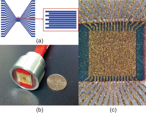
(a) PMN-PT kerfless phased array pattern with 32-element, (b) photo of PMN-PT kerfless phased array prototype, and (c) photo of top electrodes of the array.
Fig. 2.
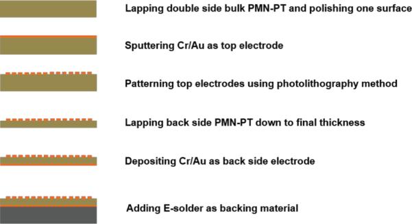
Fabrication flow of PMN-PT kerfless phased array.
C. Transducer Characterizations
To validate the array design, a 2-D finite element model (PZFlex, Weidlinger Associates Inc., Mountain View, CA) was used to predict the array performance. The finite element modeling is capable to provide an accurate prediction of high-frequency array performance as well as reduce the number of time-consuming prototype fabrication runs.
Several standard non-imaging transducer tests were first performed on the array to characterize its performance including electrical impedance, pulse–echo response, insertion loss, combined electrical and mechanical crosstalk, and single-element azimuthal one-way angular response, or directivity [15]. Measured results were compared with simulation.
D. Phantom Imaging Evaluations
The ultimate performance indication of a transducer was determined by its imaging capability. In the imaging evaluation, the kerfless phased array was paired with a 32-channel high-frequency ultrasound imaging system to image a fine-wire phantom. This approach was used to determine the array's spatial resolution.
The customized digital imaging system sampled the echo signals at 140 megasamples per second (MSPS). In total, 128 scanning beams were focused and steered within ±30°. No apodization or thresholding was implemented during imaging reconstruction. Some specifications of the imaging system are given in Table III.
TABLE III.
Specifications of 32-Channel Digital Imaging System.
| Number of transmit channels | 32 |
| Number of receive channels | 32 |
| Number of bits per channel | 12 |
| Number of samples per scan line | 2048 (around 11 mm depth) |
| Transmit focus | One focus at 4 mm |
| Receive focus | Dynamic, updated with every sample |
The imaging target was five 20-μm-diameter tungsten wires (California Fine Wire Company, Grover Beach, CA) which were arranged diagonally with equal distance in the axial (1.5 mm) and lateral (0.65 mm) directions, respectively (Fig. 3). In the experiment, the wire phantom target was immersed in degassed water.
Fig. 3.
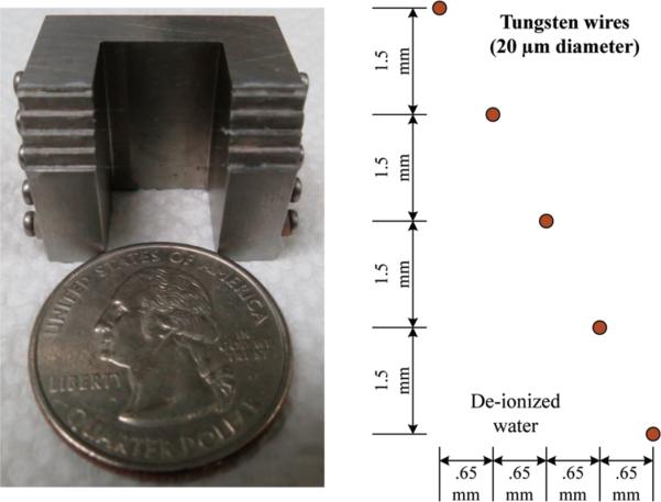
The arrangement of imaging target with five tungsten wires.
In the present work, the kerfless phased array was also evaluated for PA imaging; because PA signals are subject to only one-way, the impact to the imaging quality caused by crosstalk is expected to be less than round-trip. A graphite rod with 0.5 mm diameter was used as a PA imaging target that has strong light absorption characteristics [37]. In our PA imaging system, a pulsed Q-switched Nd:YAG laser (Spectra-Physics Explorer 532–2Y, Newport Corp., Santa Clara, CA) was used as a PA excitation source. The free-space laser output was coupled by a 4× objective lens into an optical fiber and then delivered to the lead strip surface. The array was placed in front of the graphite rod and connected to the high-frequency ultrasonic phased array system. The high-frequency ultrasonic phased array system was used to generate US pulses and receive both US and PA signals. Received signals are digitized and processed in the computer.
III. Results
A. Performance Evaluation
The simulated and measured frequency dependence of the electrical impedance and phase of a representative array element are displayed in Figs. 4(a) and 4(b), respectively. The simulated and measured results are compared in Table IV. It is shown that the measured results are in good agreement with the simulated ones. The measured results showed that the electrical impedance at a phase peak was 69.9 ± 2.9 Ω at 40 MHz. The series (fr) and parallel (fa) resonant frequencies were 39.4 ± 1.0 MHz and 46.1 ± 1.1 MHz, respectively. The electromechanical coupling coefficient (kt) of the array elements was found to be 0.56 ± 0.02, which was comparable to that of the bulk PMN-PT single crystal (0.58, HC materials, Bolingbrook, IL).
Fig. 4.
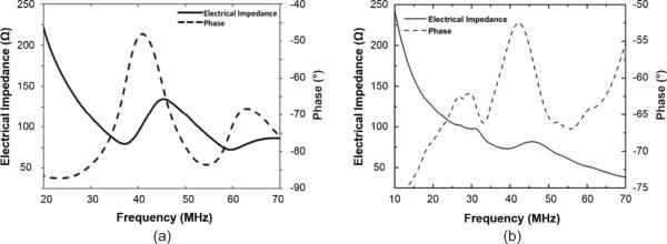
(a) Simulated and (b) measured electrical impedance and phase of a representative array element.
TABLE IV.
Comparison of Simulated and Measured Electrical Impedance Results.
| Property | PZFlex | Measured |
|---|---|---|
| Impedance | 85.9 Ω @ 40 MHz | 69.9 ± 2.9 Ω @ 40 MHz |
| f r | 37.3 MHz | 39.4 ± 1.0 MHz |
| f a | 45.5 MHz | 45.7 ± 1.1 MHz |
| k t | 0.61 | 0.56 ± 0.02 |
The simulated and measured pulse–echo responses and their corresponding FFT spectra of a representative array element are shown in Figs. 5(a) and 5(b), respectively. The center frequency (fc) and −6-dB bandwidth (BW) of the 32 array elements were measured at 42.6 ± 0.4 MHz and 34.1 ± 2.2%, respectively. The measured insertion loss (IL) for all array elements was 20.0 ± 1.3 dB. Comparison of simulated and measured results is shown in Table V. The measured results were found to be comparable to the simulation.
Fig. 5.
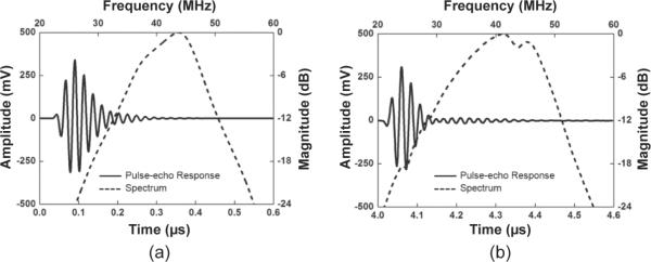
(a) Simulated and (b) measured pulse–echo response and the FFT spectrum of a representative array element.
The simulated and measured crosstalks for the array are shown in Figs. 6(a) and 6(b), respectively. The measured crosstalk near the center frequency of the array was <−10 dB, which was higher than that of the conventional kerfed arrays, as expected [22]. Although the maximum crosstalk value was found to be identical in both measured and simulated results, the crosstalk between the element and 2-elements away was found to be higher than that between the element and the adjacent elements in the measurement. This phenomenon may be a result of the electrical design in the present work. Because the major source of crosstalk in the array is electrical in nature, the variations of crosstalk magnitude and frequency could be affected significantly by adopting different electrical connection designs. In the present work, the array is kerfless with interdigitated electrode (IDE) as an electrode pattern. Because the electrical traces of the element and that of the element which is 2 elements away are connected to the same side of the electrode in the IDE structure, their crosstalk should be higher than that between the element and its adjacent one.
Fig. 6.
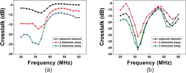
(a) Simulated and (b) measured crosstalk of the array by PZFlex.
Compared with the conventional kerfed arrays, the crosstalk of the kerfless array is high, resulting in a reduction of the element acceptance angle. The measured oneway directivity pattern for a representative array element is shown in Fig. 7. The −6-dB acceptance angle was 10° for the kerfless array element. As expected, the kerfless array directivity suffered from increased crosstalk between elements.
Fig. 7.
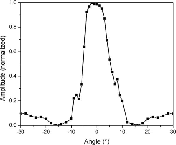
Measured one-way directivity for a single array element.
The measured results of the kerfless array are summarized and compared with PZFlex modeling results in Table VI. It is obvious that the measured results are in good accordance to the measured results.
TABLE VI.
Comparison Between Measured and Modeling Results for the Array.
| Property | Measured | PZFlex |
|---|---|---|
| Number of elements | 32 | 32 |
| Average fc | 42.6 MHz | 41.5 MHz |
| Highest/lowest fc | 43.4 MHz / 41.7 MHz | 42.1 MHz / 40.4 MHz |
| Average –6-dB BW | 34% | 31% |
| Highest/lowest –6-dB BW | 37.3% / 29.0% | 33.1% / 28.5% |
| Average Vp-p | 653.7 mV (no gain) | 534.8 mV (no gain) |
| Highest/lowest Vp-p | 898.0 mV / 391.5 mV | 654.2 mV / 162.6 mV |
| Average IL | 20.0 dB | N/A |
| Highest/lowest IL | 23.7 dB / 18.1 dB | N/A |
| –6 dB / –20 dB pulse length | 63 / 169 ns | 69 / 147 ns |
| k t | 0.557 | 0.612 |
| Crosstalk | <–5 dB | <–5 dB |
Table VII shows performance comparison between a 35-MHz PZT ceramic 2–2 composite array [15], a 32-MHz PZT ceramic kerfless array [22], and the PMN-PT single-crystal kerfless array. The insertion loss of kerfless array was 2.8 dB higher than composite array and comparable to the ceramic kerfless array. The bandwidth of the kerfless array was about 20% to 30% lower than the composite array and the ceramic kerfless array. However, given the simplicity of the kerfless array design with only one matching layer, lower bandwidth can be improved in more comprehensive design in the future.
TABLE VII.
Comparison Between Measured and Modeling Results for the Array.
| Previous work |
Current work |
||
|---|---|---|---|
| Property | Composite array [15] | Kerfless array [22] | Kerfless array |
| Material | PZT ceramic 2–2 composite | PZT ceramic | PMN-PT single crystal |
| Number of elements | 64 | 64 | 32 |
| Number of open / shorted elements | 1 / 0 | 13 / 2 | 0 / 0 |
| Average center frequency | 35.3 MHz | 32 MHz | 42.6 MHz |
| Average bandwidth (–6 dB) | 55% | 61% | 34% |
| Average sensitivity | 403 mV (no gain) | 1.65 V (20 dB gain) | 653.7 mV (no gain) |
| Insertion loss* | 22.8 dB | 19.9 dB | 20.0 dB |
| –20 dB pulse length* | 94 ns | 124 ns | 169 ns |
| Crosstalk | <–24 dB | <–11 dB | <–5 dB |
| Transmit acceptance angle (–6 dB)* | 22° | 22° | 12° |
Measured on a representative array element.
B. Imaging Evaluation
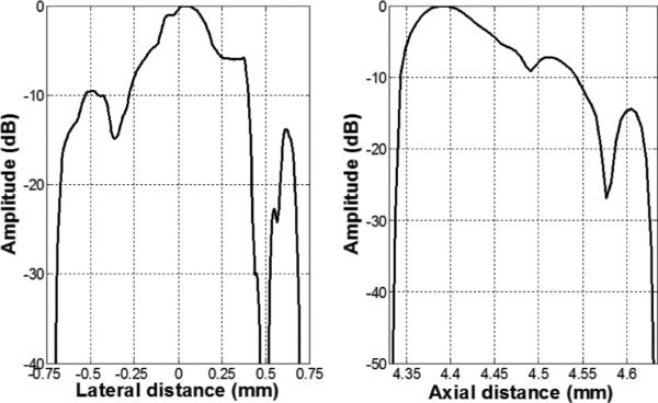
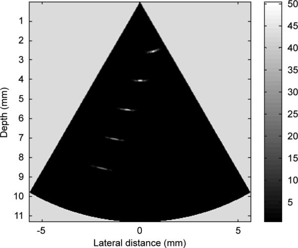
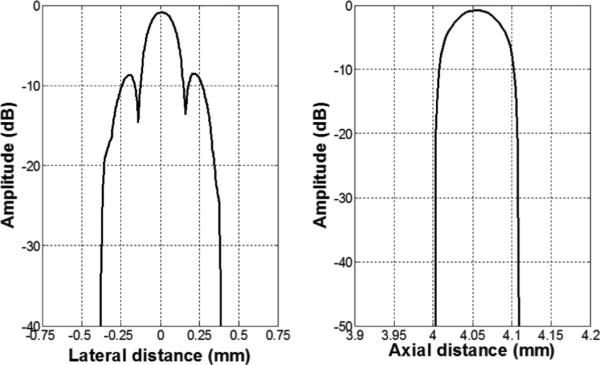
A B-mode image of the five-wire phantom is shown in Fig. 8, which is in a linear gray scale and 50 dB dynamic range. Plots of the axial and lateral line spread functions for the second wire are shown in Fig. 9. The measured full-width at half-maximum (FWHM) spatial resolutions were 467 μm and 118 μm in lateral and axial directions, respectively. For comparison, Field II [38], [39] simulation is shown in Fig. 10. The lateral and axial profiles of the second wire are shown in Fig. 11. The theoretical lateral and axial resolution are 229 μm and 90 μm, respectively. Large discrepancies between theoretical (Field II) and measured resolutions are attributed to the basis of the Field II program. In the simulation, wires were considered as perfect point sources that should not be the case in reality. Also, because Field II is simulated based on the transducer geometry, it cannot differentiate the kerfless structure for simulation.
Fig. 8.
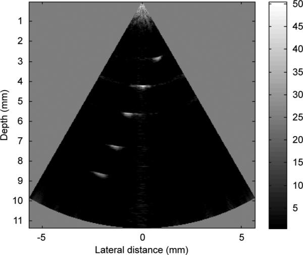
Wire phantom image with the 40 MHz PMN-PT kerfless phased array.
Fig. 9.
Lateral (left) and axial (right) line spread functions for the second wire of the wire phantom.
Fig. 10.
Field II simulation wire phantom image of 40-MHz phased array.
Fig. 11.
Field II simulation lateral (left) and axial (right) line spread functions for the second wire of the wire phantom.
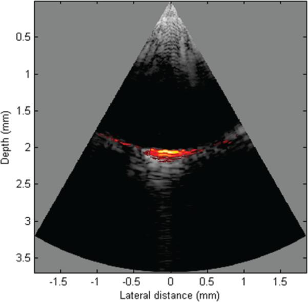
A co-registered US and PA image of the graphite rod is shown in Fig. 12 using a linear gray scale and 50 dB dynamic range. The scan angle is also set at ± 30°. No apodization or thresholding was implemented during reconstruction.
Fig. 12.
Co-registered US and PA image of a graphite rod using the 40-MHz PMN-PT single-crystal kerfless phased array.
IV. Summary
A 40-MHz 32-element kerfless phased array using PMN-PT single crystal was modeled, fabricated, and tested. The aperture size of active area was only 1.0 × 1.0 mm. The measured results showed that the array exhibited a center frequency of 40 MHz, a bandwidth of 34% at −6 dB, and an insertion loss of 20 dB at the center frequency. Its imaging capability has been demonstrated by US wire phantom imaging and PA graphite rod imaging. The FWHM spatial lateral and axial resolutions were measured to be 467 μm and 118 μm, respectively. By using PMN-PT single crystal as the transducer element, this array has higher frequency and is more sensitive than the previously built composite and kerfless arrays [15], [22]. As expected, the kerfless array directivity suffered from high crosstalk between elements. Based upon the results presented, the kerfless array technology appears to be a viable alternative for forward-looking IVUS and EUS applications.
TABLE V.
Comparison of Simulated and Measured Pulse-Echo Response and its FFT Spectrum.
| Property | PZFlex | Measured |
|---|---|---|
| fc (MHz) | 41.5 ± 0.6 | 42.6 ± 0.4 |
| –6-dB BW (%) | 31.3 ± 1.3 | 34.1 ± 2.2 |
| Vpp (mV) | 534.8 ± 127.5 | 653.7 ± 100.3 |
| –6-dB / –20-dB pulse length | 69 / 147 ns | 63 / 169 ns |
| Compensated IL (dB) | N/A | 20.0 ± 1.3 |
Acknowledgments
The authors thank Dr. H. H. Kim and J. A. Williams for their suggestions and technical support.
This work was supported by National Institutes of Health (NIH) grant P41-EB002182.
Biography
 Ruimin Chen (S’07) received his B.S. degree from the University of Electronics Science and Technology of China, Chengdu, China, and his M.S. degree from the University of Southern California, Los Angeles, CA, in 2006 and 2008, respectively, both in biomedical engineering. He is currently a Ph.D. student in the NIH Resource Center for Medical Ultrasonic Transducer Technology at the Department of Biomedical Engineering of University of Southern California.
His research interests include the design, modeling, and fabrication of high-frequency ultrasonic transducers and arrays for medical imaging applications, piezoelectric material characterization, and photoacoustic imaging.
 Nestor E. Cabrera-Munoz (S’12) obtained a B.S. degree in mechanical-electrical engineering from the Monterrey Institute of Technology (ITESM Campus Monterrey, Mexico) in 2005, and an M.S. degree in biomedical engineering from the University of Southern California, Los Angeles, CA, in 2010. He is now pursuing a Ph.D. degree in biomedical engineering at the University of Southern California, focusing his research on high-frequency ultrasonic transducers and arrays. Before joining the biomedical engineering field, he worked as an R&D principal engineer and project manager for a European company specialized in HVAC, obtaining the American and German patents for a new product. He also worked as a project engineer for an American automotive company in its power-train division. His current interests include the design, modeling, fabrication, and testing of ultrasonic transducers and ultrasonic arrays for medical and NDT applications. Mr. Cabrera-Munoz is a student member of IEEE and the American Society of Mechanical Engineers.
 Kwok Ho Lam received M.Phil. and Ph.D. degrees in applied physics from the Hong Kong Polytechnic University in 2002 and 2006, respectively. He worked as a Postdoctoral Fellow on vibration control applications of smart materials in civil and environmental engineering at the Hong Kong Polytechnic University from 2007 to 2009. After working on medical ultrasonic transducers in applied physics for two years, he then joined the NIH Resource Center for Medical Ultrasonic Transducer Technology at the University of Southern California as a Research Associate and engaged in ultrahigh-frequency ultrasonic transducer development. Dr. Lam is currently an Assistant Professor in Department of Electrical Engineering at the Hong Kong Polytechnic University. His research interests include multifunctional smart materials, smart sensor and actuator technology, ultrasonic transducer technology, acoustic tweezers, energy harvesting applications, and condition and structural health monitoring.
 Hsiu-sheng Hsu received his Ph.D. degree in materials science from the University of Southern California, Los Angeles, CA, in 2012. His research interests include the development of ferroelectric thin films, MEMS technology, and design and fabrication of high-frequency ultrasonic transducers for acoustic tweezers applications. Dr. Hsu currently works as a principal engineer at Taiwan Semiconductor Manufacturing Company.
 Fan Zheng received the Ph.D. degree in biomedical engineering from the University of Southern California, Los Angeles, CA, in 2012. His research interests include high-frequency ultrasound phased arrays in medical and nondestructive testing application.
 Qifa Zhou received his Ph.D. degree from the Department of Electronic Materials and Engineering at Xi'an Jiaotong University, China, in 1993. He is currently a Research Professor at the NIH Resource on Medical Ultrasonic Transducer Technology and the Department of Biomedical Engineering and Industry and System Engineering at the University of Southern California, Los Angeles, CA. Before joining USC in 2002, he worked in the Department of Physics at Sun Yat-Sen University of China, the Department of Applied Phys ics at Hong Kong Polytechnic University, and the Materials Research Laboratory at The Pennsylvania State University.
Dr. Zhou is a senior member of the IEEE Ultrasonics, Ferroelectrics, and Frequency Control (UFFC) Society and a member of the society's Ferroelectric Committee. He is a member of the technical program Committee of the IEEE International Ultrasonics Symposium (IUS). He is an Associate Editor of the IEEE Transactions on Ultrasonics, Ferroelectrics, and Frequency Control. He is also a fellow of the International Society for Optics and Photonics (SPIE) and the American Institute for Medical and Biological Engineering (AIMBE). His current research interests include the development of piezoelectric thin films, MEMS technology, nanocomposites, and fabrication of high-frequency ultrasound transducers and arrays for medical imaging applications such as photoacoustic imaging and intravascular imaging. He has published more than 130 journal papers in this area.
 K. Kirk Shung obtained a B.S. degree in electrical engineering from Cheng-Kung University in Taiwan in 1968; an M.S. degree in electrical engineering from University of Missouri, Columbia, MO, in 1970; and a Ph.D. degree in electrical engineering from University of Washington, Seattle, WA, in 1975. He taught at The Pennsylvania State University, University Park, PA, for 23 years before moving to the Department of Biomedical Engineering, University of Southern California, Los Angeles, CA, as a professor in 2002. He has been the director of the NIH Resource on Medical Ultrasonic Transducer Technology since 1997.
Dr. Shung is a Life Fellow of IEEE, and a fellow of the Acoustical Society of America and the American Institute of Ultrasound in Medicine. He is a founding fellow of the American Institute of Medical and Biological Engineering. He received the IEEE Engineering in Medicine and Biology Society Early Career Award in 1985 and was the coauthor of a paper that received the best paper award for the IEEE Transactions on Ultrasonics, Ferroelectrics and Frequency Control (UFFC) in 2000. He was elected an outstanding alumnus of Cheng-Kung University in Taiwan in 2001. He was selected as the distinguished lecturer for the IEEE UFFC society for 2002–2003. He received the Holmes Pioneer Award in Basic Science from American Institute of Ultrasound in Medicine in 2010. He was selected to receive the academic career achievement award from the IEEE Engineering in Medicine and Biology Society in 2011.
Dr. Shung has published more than 400 papers and book chapters. He is the author of the textbook Principles of Medical Imaging, published by Academic Press in 1992, and the textbook Diagnostic Ultrasound: Imaging and Blood Flow Measurements, published by CRC Press in 2005. He co-edited the book Ultrasonic Scattering by Biological Tissues, published by CRC Press in 1993. He is an associate editor of the IEEE Transactions on Ultrasonics, Ferroelectrics and Frequency Control and a member of the editorial board of Ultrasound in Medicine and Biology. Dr. Shung's research interest is in ultrasonic transducers, high-frequency ultrasonic imaging, ultrasound microbeams, and ultrasonic scattering in tissues.
References
- 1.Potkin BN, Bartorelli AL, Gessert JM, Neville RF, Almagor Y, Roberts WC, Leon MB. Coronary artery imaging with intravascular high-frequency ultrasound. Circulation. 1990 May;81(5):1575–1585. doi: 10.1161/01.cir.81.5.1575. [DOI] [PubMed] [Google Scholar]
- 2.Nissen SE, Yock P. Intravascular ultrasound novel patho-physiological insights and current clinical applications. Circulation. 2001 Jan.103(4):604–616. doi: 10.1161/01.cir.103.4.604. [DOI] [PubMed] [Google Scholar]
- 3.Foster FS, Pavlin CJ, Harasiewicz KA, Christopher DA, Turnbull DH. Advances in ultrasound biomicroscopy. Ultrasound Med. Biol. 2000 Jan.26(1):1–27. doi: 10.1016/s0301-5629(99)00096-4. [DOI] [PubMed] [Google Scholar]
- 4.Vazquez-Sequeiros E, Wiersema MJ. High-frequency US catheter-based staging of early esophageal tumors. Gastrointest. Endosc. 2002 Jan.55(1):95–99. doi: 10.1067/mge.2002.120099. [DOI] [PubMed] [Google Scholar]
- 5.Hurlstone DP, Cross SS, Sanders DS. 20-MHz high-frequency endoscopic ultrasound-assisted endoscopic mucosal resection for colorectal submucosal lesions: A prospective analysis. J. Clin. Gastroenterol. 2005 Aug.39(7):596–599. doi: 10.1097/01.mcg.0000170740.82004.39. [DOI] [PubMed] [Google Scholar]
- 6.O'Donnell M, Eberle MJ, Stephens DN, Litzza JL, San Vicente K, Shapo BM. Synthetic phased arrays for intraluminal imaging of coronary arteries. IEEE Trans. Ultrason. Ferroelectr. Freq. Control. 1997 May;44(3):714–721. [Google Scholar]
- 7.Tekes C, Karaman M, Degertekin FL. Optimizing circular ring arrays for forward-looking IVUS imaging. IEEE Trans. Ultrason. Ferroelectr. Freq. Control. 2011 Dec.58(12):2596–2607. doi: 10.1109/TUFFC.2011.2123. [DOI] [PMC free article] [PubMed] [Google Scholar]
- 8.Evans JL, Ng KH, Vonesh MJ, Kramer BL, Meyers SN, Mills TA, Kane BJ, Aldrich WN, Jang YT, Yock PG. Arterial imaging with a new forward-viewing intravascular ultra-sound catheter, I. Initial studies. Circulation. 1994 Feb.89(2):712–717. doi: 10.1161/01.cir.89.2.712. [DOI] [PubMed] [Google Scholar]
- 9.Ng KH, Evans JL, Vonesh MJ, Meyers SN, Mills TA, Kane BJ, Aldrich WN, Jang YT, Yock PG, Rold MD. Arterial imaging with a new forward-viewing intravascular ultrasound catheter, II. Three-dimensional reconstruction and display of data. Circulation. 1994 Feb.89(2):718–723. doi: 10.1161/01.cir.89.2.718. [DOI] [PubMed] [Google Scholar]
- 10.Liang DH, Hu BS. A forward-viewing intravascular ultra-sound catheter for intracoronary use. Biomed. Instrum. Technol. 1997 Jan-Feb;31(1):45–53. [PubMed] [Google Scholar]
- 11.Nguyen-Dinh A, Ratsimandresy L, Mauchamp P, Dufait R, Flesch A, Lethiecq M. High frequency piezo-composite transducer array designed for ultrasound scanning applications. Proc. IEEE Ultrasonics Symp. 1996:943–947. [Google Scholar]
- 12.Michau S, Mauchamp P, Dufait R. Piezocomposite 30 MHz linear array for medical imaging: Design challenges and performances evaluation of a 128 element array. Proc. IEEE Ultrasonics Symp. 2004:898–901. [Google Scholar]
- 13.Foster FS, Mehi J, Lukacs M, Hirson D, White C, Chaggares C, Needles A. A new 15-50 MHz array-based micro-ultra-sound scanner for preclinical imaging. Ultrasound Med. Biol. 2009 Oct.35(10):1700–1708. doi: 10.1016/j.ultrasmedbio.2009.04.012. [DOI] [PubMed] [Google Scholar]
- 14.Lukacs M, Yin J, Pang G, Garcia RC, Cherin E, Williams R, Mehi J, Foster FS. Performance and characterization of new micromachined high-frequency linear arrays. IEEE Trans. Ultrason. Ferroelectr. Freq. Control. 2006 Oct.53(10):1719–1729. doi: 10.1109/tuffc.2006.105. [DOI] [PubMed] [Google Scholar]
- 15.Cannata JM, Williams JA, Zhou Q, Ritter TA, Kirk Shung K. Development of a 35-MHz piezo-composite ultrasound array for medical Imaging. IEEE Trans. Ultrason. Ferroelectr. Freq. Control. 2006 Jan.53(1):224–236. doi: 10.1109/tuffc.2006.1588408. [DOI] [PubMed] [Google Scholar]
- 16.Oralkan O, Hansen ST, Bayram B, Yaralioglu GG, Ergun AS, Khuri-Yakub T. CMUT ring arrays for forward-looking intravascular imaging. Proc. IEEE Ultrasonics Symp. 2004:403–406. [Google Scholar]
- 17.Degertekin FL, Guldiken RO, Karaman M. Annular-ring CMUT arrays for forward-looking IVUS: transducer characterization and imaging. IEEE Trans. Ultrason. Ferroelectr. Freq. Control. 2006 Feb.53(2):474–482. doi: 10.1109/tuffc.2006.1593387. [DOI] [PubMed] [Google Scholar]
- 18.Yeh DT, Oralkan O, Wygant IO, O'Donnell M, Khuri-Yakub BT. 3-D ultrasound imaging using a forward-looking CMUT ring array for intravascular/intracardiac applications. IEEE Trans. Ultrason. Ferroelectr. Freq. Control. 2006 Jun.53(6):1202–1211. doi: 10.1109/tuffc.2006.1642519. [DOI] [PubMed] [Google Scholar]
- 19.Morton CE, Lockwood GR. Evaluation of kerfless linear arrays. Proc. IEEE Ultrasonics Symp. 2002:1257–1260. [Google Scholar]
- 20.Zhu BP, Chan NY, Dai JY, Shung KK, Takeuchi S, Zhou QF. New fabrication of high-frequency (100-MHz) ultrasound PZT film kerfless linear array. IEEE Trans. Ultrason. Ferroelectr. Freq. Control. 2013 Apr.60(4):854–857. doi: 10.1109/TUFFC.2013.2635. [DOI] [PMC free article] [PubMed] [Google Scholar]
- 21.Zhu BP, Wu DW, Zhang Y, Ou-Yang J, Chen S, Yang XF. Sol–gel derived PMN–PT thick films for high frequency ultrasound linear array applications. Ceram. Int. 2013;39(8):8709–8714. [Google Scholar]
- 22.Cannata JM, Williams JA, Shung KK. A kerfless 30 MHz linear ultrasonic array. Proc. IEEE Ultrasonics Symp. 2005:109–112. [Google Scholar]
- 23.Morton CE, Lockwood GR. Design of a 40 MHz annular array. Proc. IEEE Ultrasonics Symp. 2001:1135–1138. [Google Scholar]
- 24.Dmore CEM, Brown JA, Lockwood GR. Investigation of cross talk in kerfless annular arrays for high-frequency imaging. IEEE Trans. Ultrason. Ferroelectr. Freq. Control. 2013 May;53(5):1046–1056. doi: 10.1109/tuffc.2006.1632694. [DOI] [PubMed] [Google Scholar]
- 25.Harman G. Wire Bonding in Microelectronics. Mc-Graw-Hill Professional; New York, NY: 2010. [Google Scholar]
- 26.Bezanson A, Garland P, Adamson R, Brown JA. Fabrication of a miniaturized 64-element high-frequency phased array. Proc. IEEE Ultrasonics Symp. 2012:2114–2117. doi: 10.1109/TUFFC.2014.6689774. [DOI] [PubMed] [Google Scholar]
- 27.Wu DW, Zhou Q, Geng X, Liu CG, Djuth F, Shung KK. Very high frequency (beyond 100 MHz) PZT kerfless linear arrays. IEEE Trans. Ultrason. Ferroelectr. Freq. Control. 2009 Oct.56(10):2304–2310. doi: 10.1109/TUFFC.2009.1311. [DOI] [PMC free article] [PubMed] [Google Scholar]
- 28.Park SE, Shrout TR. Characteristics of relaxor-based piezoelectric single crystals for ultrasonic transducers. IEEE Trans. Ultrason. Ferroelectr. Freq. Control. 1997 Sep.44(5):1140–1147. [Google Scholar]
- 29.Lam KH, Chan HLW, Luo HS, Yin QR, Yin ZW. Piezoelectrically actuated ejector using PMN-PT single crystal. Sens. Actuators A. 2005 May;121(1):197–202. [Google Scholar]
- 30.Edwards G, Chan HLW, Batten A, Lam KH, Luo HS, Scott DA. PMN-PT single crystal transducer for non-destructive evaluation. Sens. Actuators A. 2006 Nov.132(2):434–440. [Google Scholar]
- 31.Lam KH, Lo CY, Dai JY, Chan HLW, Luo HS. Enhanced ME effect in a stress–biased PMN–PT single crystal / Terfenol–D alloy magnetoelectric sensor. J Appl. Phys. 2011 Jan.109 art. no. 024505. [Google Scholar]
- 32.Zhang S, Li F. High performance ferroelectric relaxor-PbTiO3 single crystals: Status and perspective. J. Appl. Phys. 2012 Feb.111(3) art. no. 031301. [Google Scholar]
- 33.Lau ST, Lam KH, Chan HLW, Choy CL, Luo HS, Yin QR, Yin ZW. Ferroelectric lead magnesium niobate-lead titanate single crystals for ultrasonic hydrophone applications. Mater. Sci. Eng. B. 2004 Aug.111(1):25–30. [Google Scholar]
- 34.Zhou Q, Xu X, Gottlieb EJ, Sun L, Cannata JM, Ameri H, Humayun MS, Han P, Shung KK. PMN-PT single crystal, high-frequency ultrasonic needle transducers for pulsed-wave Doppler application. IEEE Trans. Ultrason. Ferroelectr. Freq. Control. 2007 Mar.54(3):668–675. doi: 10.1109/tuffc.2007.290. [DOI] [PubMed] [Google Scholar]
- 35.Lam KH, Chen Y, Cheung KF, Dai JY. PMN-PT single crystal focusing transducer fabricated using a mechanical dimpling technique. Ultrasonics. 2012 Jan.52(1):20–24. doi: 10.1016/j.ultras.2011.06.004. [DOI] [PubMed] [Google Scholar]
- 36.Chen Y, Lam KH, Zhou D, Cheng WF, Dai JY, Luo HS, Chan HLW. High frequency PMN–PT single crystal focusing transducer fabricated by a mechanical dimpling technique. Ultrasonics. 2013 Feb.53(2):345–349. doi: 10.1016/j.ultras.2012.06.017. [DOI] [PubMed] [Google Scholar]
- 37.Kong F, Chen YC, Lloyd HO, Silverman RH, Kim HH, Cannata JM, Shung KK. High-resolution photoacoustic imaging with focused laser and ultrasonic beams. Appl. Phys. Lett. 2009 Jan.94(3) doi: 10.1063/1.3073749. art. no. 033902. [DOI] [PMC free article] [PubMed] [Google Scholar]
- 38.Jensen JA. Field: A program for simulating ultrasound systems. Med. Biol. Eng. Comput. 1996;34(suppl. 1)(pt. 1):351–353. [Google Scholar]
- 39.Jensen JA, Svendsen NB. Calculation of pressure fields from arbitrarily shaped, apodized, and excited ultrasound transducers. IEEE Trans. Ultrason. Ferroelectr. Freq. Control. 1992 Mar.39(2):262–267. doi: 10.1109/58.139123. [DOI] [PubMed] [Google Scholar]


