

Abstract
Isotropic detectors with spherical scattering tips are commonly used for in-vivo dosimetry of light fluence rate during photodynamic therapy (PDT). These detectors are typically calibrated in-air. It has been well established that the response of an isotropic detector is a function of the refractive index (n) of the surrounding medium when it is surrounded by an infinite medium of uniform n. However, there are few, if any, studies of the isotropic detector response when the detector is placed in a secondary medium, such as air, before it is placed inside the infinite uniform medium. This condition often arises when one places the isotropic detector inside an air-filled catheter which is then inserted into a turbid medium, such as tissue. We have performed theoretical and experimental studies to determine the correction factors in water (n = 1.33), which has a refractive index similar to that of tissue (n = 1.4). We found that the resulting correction factor is almost the same (within 20%) as the correction factor for the outermost medium (the water) rather than the immediate medium surrounding the isotropic detector (air). The detector correction factor is also a function of the index of refraction of the probe material. For a 1-mm diameter probe from CardioFocus, the detector correction factor varied from 1 (in air) to 1.09 (at air-water interface) to 1.49 (completely submerged in water). At the air-water interface the spherical bulb of the isotropic detector is placed half in air and half in water. For a 0.5-mm diameter probe from the same company, it varied from 1 (in air) to 1.32 (at air-water interface) to 1.87 (in water). For a 0.3-mm diameter probe from the same company, it varied from 1 (in air) to 1.32 (at air-water interface) to 1.71 (in water). We have also found that the detector response changes by less than 10% when the detector position is varied from touching the catheter wall closest to the light source, to not touching, to touching the catheter wall farthest from the light source. The calibration factors between individual isotropic detectors of the same type varied within 5% for all detector types. Thus mean correction factor can be used for each individual isotropic detector of the same type.
Keywords: In-vivo light dosimetry, detector calibration factor, diffusion approximation
1. INTRODUCTION
Isotropic detectors made of scattering spherical bulbs are routinely used in clinic for photodynamic therapy as interstitial in-vivo dosimeters (1). The response of isotropic detector is, however, a function of the indices of refraction of the surrounding medium and the scattering bulb because the signal detected by the isotropic detector depends on the amount of light transmitted into the scattering bulb from the surrounding medium (2). If an isotropic detector is calibrated in air and is subsequently used in tissue, then a correction factor must be applied. This correction factor can be as large as 2.0, depending on the indices of refraction of the surrounding medium and the scattering bulb.
Often times the isotropic detector is first inserted into an air-filled catheter, which is then inserted into the tissue. Under this condition, multiple medium layers existed surrounding the isotropic detector: the medium immediately surrounding the detector is air; it is then surrounded by the tissue (if one ignores the thin catheter medium). We present experimental measurement as well as theoretical analysis to show that the detector calibration factor is not determined by the medium immediately surrounding the detector, but rather by the outmost bulk medium. As a result, the detector correction factor for a detector inside an air-filled catheter is approximately the same as that for a bare isotropic detector (without the catheter) immersed inside the same bulk medium.
2. METHODS AND MATERIALS
1. Experimental determination of detector calibration factor
The experimental setup to determine the detector calibration factor, β, is shown in Fig. 1. The detector calibration factor, β, for a detector merged in a medium at depth d is determined by measurements at four points:
| (1) |
where ϕwat and ϕair are the light fluence rates measured in water and in air, respectively, at depth d and dref. ϕ0(d) and ϕ0(dref) are the light fluence rates measured in air at the same locations. The reference depth, dref, is typically chosen to be 5 mm above the air-water interface in air. The ratio ϕ0(d)/ϕ0(dref) corrects the light fluence rate variation due to divergence of the light beam (or inverse square law) since the incident laser light is not strictly collimated. If the laser power for setups (a) and (b) in Fig. 1 is exactly the same, then ϕair(dref) = ϕ0(dref) and Eq. (1) can be further simplified to β = ϕ0(d)/ϕwat(d).
Fig. 1.

Schematics of the experimental setup used to determine the detector calibration factor. The reference depth is defined as 5 mm above the air-medium (water) interface, in air. The detector calibration is performed under a collimator laser source under a flat-cut fiber fitted with microlens.
To characterize the effect of radius of the scattering bulb on the detector calibration factor, a measurement of β is performed for three types of detectors with different bulb radius at the interface between water and air, d = 0 cm. This measurement is made to demonstrate the impact of scattering bulb size and expected reduction of β because half of the scattering bulb now lies within air and only half lies within water.
To determine the influence of the catheter on the detector calibration factors, we measured β for three different geometries: (a) detector in water-filled catheter in water; (b) detector in air-filled catheter in water; (c) detector in water-filled catheter in air. These results are compared to β measured for the bare isotropic detector without a catheter. These experiments are designed to test whether the detector calibration factor is determined by the immediate surounding medium of the detector or by the outmost medium. Additional experiments are performed to determine the variation of β when the detector position is varied from touching the catheter wall closest to the light source, to not touching, to touching the catheter wall farthest from the light source.
2. Diffusion theory of detector calibration factor
2.1 Two layered medium
This section will summarize the results of the work of Star and Marijnissen (3). This work considers an isotropic detector composed of a nonscattering medium (fiber) of radius r1 surrounded by a scattering bulb of index n2 and radius r2 embedded in a medium of index n1 (see Fig. 2). For simplicity, the outer medium is considered to be nonscattering. The sphere is illuminated by an isotropic incidence of I0.
Figure 2.

Schematics of the two layered spherical model. The index of refraction for the surrounding medium is n1. The index of refraction for the scattering medium (the isotropic detector) is n2. The index of refraction for the inner most medium is n0. The radius of the scattering bulb is r2 and the radius for the detector fiber is r1. R12, R21 is the reflectance coefficient for light radiance leaving and entering interface r2. R20 is the reflectance factor for light radiance entering interface r0.
In the scattering bulb, the fluxes in the inward (F−) and outward (F+) directions can be found by solving equations 4 and 5 of that paper (3):
| (1a) |
| (2a) |
The magnitudes of the fluxes are defined in terms of the radiance: and , where μ is the cosine of the angle with the radial vector. The outward and inward fluxes are related to the radiance by
| (2) |
The above equations are subject to boundary conditions at each of the two boundaries. At r2, the interface between the bulb and the surrounding medium, the boundary condition for the radiance is
| (3) |
where r21 is the Fresnel coefficient for reflection of light incident from the scattering bulb with index n2 onto the surrounding medium with index n1. Expanding Eq. (6) using Eq. (5), we get for the left-hand side,
| (4) |
The first term of the right-hand side yields
| (5) |
where is the reflectance coefficient for complete isotropic light incident from medium 2 onto medium 1 (see Fig. 2) and . The source term (the last term in the right-hand side of Eq. 3) gives
| (6) |
where is the reflectance coefficient for complete isotropic light incident from medium 1 onto medium 2 (see Fig. 2). Combining Eqs. (3) through (6), we obtain
| (7) |
where defines the reflectance factor for complete isotropic light incident from medium 2 onto medium 1.
As a special case, we consider a non-absorbing scattering bulb. In this case, μa is zero, so μeff becomes zero and μt′ is equal to μs′. The probe’s response is proportional to the light fluence rate at r1. According to Star et al (3), one can solve Eq. (1) for Φ(r)=2[F+(r)+F−(r)]:
| (8) |
Thus the detector response is proportional to the ratio (1-R12)/(1-R21) that is determined by the indices of refraction for the surrounding medium and the scattering bulb. R12 and R21 are the reflectance coefficients determined by
| (9a) |
| (9b) |
where r21(μ) and r12(μ) is the Fresnel reflection coefficients (ratio of reflected-to-incident radiance) for radiant incident on medium 1 from medium 2 and on medium 2 from medium 1, respectively, with an incident angle of μ = cosθ (see Fig. 2). The correction factor, defined as the relative response of the detector between the air and the medium of interest can be calculated as
| (10) |
2.2 Three layered medium
This section will extend the work of the previous section to a three-layer problem. In particular, we will consider a scattering bulb of radius r2 and index n2 surrounding a clear fiber of radius r1 as in the previous section, but we will now interpose a nonscattering layer of index nc and radius rc between the scattering bulb and the surrounding medium (see Fig. 3). The subscript c denotes the catheter. The ambient medium of index n1 is assumed to be the same as in the two-layer case.
Figure 3.

Schematics of the three layered spherical model. The index of refraction for the surrounding medium is n1. The index of refraction for the scattering medium (the isotropic detector) is n2. The index of refraction for the immediate medium surrounding the isotropic detector is nc. The index of refraction for the inner most medium is n0. The radius of the scattering bulb is r2, the radius for the detector fiber is r1, and the radius of the immediate medium is rc. R2c, Rc2 are the reflectance coefficients for light radiance leaving and entering interface r2. Rc1, R1c are the reflectance coefficients for light radiance leaving and entering the interface rc. R20 is the reflectance coefficient for light radiance entering interface r0.
In the three layered medium case, the major difference is the existence of two non-scattering mediums (n1 and nc) surrounding the scattering medium (n2). If one can relate the radiance (Li) incident on the interface at rc to the total radiance (Lr) reflected back into the medium from the interfaces at r2 and rc, one can reduce the three-layered problem into a two-layered problem. In effect, one can use the same solution in Eq. (8) but replace the reflection coefficient r12 in Eq. 9 by an effective reflection coefficient r12* = Lr/Li. Likewise, one can find an effective reflection coefficient r21* to replace r21 in Eq. 9. Thus the key of solving the three layered problem is to determine the relationship between the radiances for the two nonscattering mediums.
2.2.1 Determination of r12* for inward directed light
In the spherical case, the directions from which radiance can be incident can be categorized into two groups. First, at large angles of incidence, the incoming radiance may either (a) be totally externally reflected or (b) enter the spherical cavity in such a way that it misses the scattering sphere completely, as shown in Fig. 4a and Fig. 4b. In case (a), the critical angle for total external reflection is given by
Figure 4.
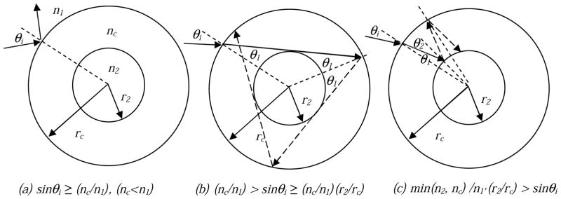
Multiple reflections in the spherical geometry: (a) total reflection at interface between n1 and nc; (b) missing the sphere with radius r2; (c) hitting the sphere with radius r2.
| (11) |
In case (b), the ray, once it misses the scattering sphere, will strike the interior of the outer sphere. Part of its radiance will be reflected (shown as the dotted line in Fig. 3b), and part will escape. The reflected portion will continue to miss the scattering sphere upon further reflection until it is completely reflected. The critical angle for missing the scattering sphere θm is given by sin−1(r2/rc). However, this is a constraint on the ray inside the clear medium, at angle θ1. This angle is related to θ1 by Snell’s law, so the critical angle for hitting the scattering sphere becomes
| (12) |
Therefore, all rays incident at angles greater than the greater of these two critical angles will be effectively totally reflected at the surface of the outer sphere (rc).
If the ray strikes at a steeper angle, it will strike the scattering sphere (Fig. 4c). The angle to the normal at which it strikes the scattering sphere can be found from the law of sines,
| (13) |
A straightforward construction with similar triangles can be used to prove that successive multiple reflections will occur at the same two angles (Fig. 4c). There is still a possibility of total internal reflection at r2. The corresponding critical angle is given by sinθ2 = n2/nc, thus according to Eq. (13) we have
| (14) |
In summary, any inward-directed beam incident on the boundary will undergo total reflection if the incident angle θi is larger than any one of the conditions defined by Eqs. (11), (12), and (14). From now on, we will refer to the minimum angle determined by Eqs. (11), (12), (14) as the effective critical angle for total reflection, θc.
Following the method of multiple reflections in a layered nonscattering medium (4,5), we find that the ratio of reflected to incident radiance for the inward radiance is given by
| (15) |
We therefore replace the reflection coefficient r12 in the two-layer problem with r12*, given by
| (16) |
2.2.2 Determination of r21* for outward directed light
For light originating in the scattering sphere, a similar analysis can be made. First, the critical angle for total internal reflection at the r2 boundary is given by
| (17) |
If the light is not totally internally reflected, it passes into the clear medium at an angle θ2 given by sinθ2 = (n2/nc)sinθi. The angle this light strikes the rc boundary with the normal, θ1 can be found from Eq. (13), and is given by . The critical angle for total internal reflection at the rc boundary is given by sinθ1≥n1/nc, or
| (18) |
Analogous to the inward-directed case, an outward-directed beam incident on the boundary at r2 will undergo total reflection if the incident angle θi is larger than the critical angle, θc, determined as the minimum of angles defined by Eqs. (17) and (18), sinθc = min(nc, n1·rc/r2)/n2.
Similar to Eq. (16), r21 can be replaced by
| (19) |
3. RESULTS AND DISCUSSION
We summarize the detector calibration factor for three different types of bare isotropic detectors (without catheter) in Table 1. It is clear that although the value of β for different types of isotropic detector is different, for the same type of detector the variation of β is within 5% for all detector types.
Table 1.
Detector water correction factor, β, measured for three different scattering bulbs in water medium.
| β | 0.3 mm bulb | 0.5 mm bulb | 1 mm bulb |
|---|---|---|---|
| Minimum | 1.706 | 1.895 | 1.444 |
| Maximum | 1.810 | 2.007 | 1.519 |
| Average | 1.77 ± 0.05 | 1.96 ± 0.03 | 1.48± 0.03 |
A comparison of β between when it is at the air-water interface and when it is in uniform medium of water shows a reduction of β, as expected (Fig. 5). The measured value were 13–14% lower than the average of β in water and in air for all detector types.
Figure 5.

Detector calibration factor, β, measured at different depths from an air-water interface for three isotropic detectors with different radius.
We verified experimentally that when isotropic detectors are used inside a catheter, it is the outmost medium rather than the immediate surrounding medium of the isotropic detector that determines the detector calibration factor β. For an isotropic detector within an air-filled catheter in water, β is within 18%, 20%, 4% of the β for a bare isotropic detector in water for 0.3, 0.5, 1 mm scattering bulbs, respectively (Table 2). Overall the agreement is within 20% of that of the bare isotropic detector for all types but will be 50% if one assume the correction factor is 1. For an isotropic detector within a water-filled catheter in air, β is within 1.3% of that of bare detector in air (Table 2). Theoretically, we predicted that the index of refraction (nc) for the intermediate medium surrounding the isotropic detector has no impact on the detector calibration factors (see Fig. 6) and is independent of the ratio of the radius (rc/r2). The calculated value gives β = 1.7 for water (n1 = 1.33), which is approximately in agreement with the 0.3 mm isotropic detector. We suspect the differnce from the measurement is caused by the difference of the index of refraction of the scattering bulb that used in the calculation (n2 = 1.5), as illustrated by analytical calculations by Star et al (3).
Table 2.
Detector water correction factor, β, measured for three different scattering bulbs in catheters filled with different insdie and outside mediums. The inner diameter of the catheter is 2 mm.
| Detector types | water filled catheter in water | air filled catheter in water | water filled catheter in air | no catheter in water |
|---|---|---|---|---|
| 0.3mm | 1.860 | 1.577 | 0.987 | 1.811 |
| 0.5mm | 1.517 | 1.583 | 0.993 | 1.914 |
| 1.0mm | 1.396 | 1.421 | 0.999 | 1.478 |
Figure 6.

Calculated correction factor as a function of the index of refraction of the outmost medium, n1, for an isotropic detector (n2 = 1.5) inside a spherical cavity with different index of refraction, nc. r2/rc is the ratio of the radius of the scattering bulb and spherical cavity for the catheter.
We also examined the effect of the detector touching the catheter wall (Table 3). The variation of β among detectors having no contact with catheter, conacting the front of catheter (toward the light source), and contacting the back of the catheter are within 10% for all isotropic detector types examined.
Table 3.
The effect of contact with the air-filled catheter on the detector calibration factor
| Detector \ conditions | no contact with catheter | Contact with front of catheter | Contact with back of catheter |
|---|---|---|---|
| 0.3mm | 1.577 | 1.508 | 1.633 |
| 0.5mm | 1.583 | 1.603 | 1.591 |
| 1.0mm | 1.421 | 1.368 | 1.339 |
Theoretically, it is remarkable that the index of refraction for the immediate surrunding medium (nc) has no impact on the detector calibration factor. The theoretical value is exactly the same as that predicted by the two layered model (Eq. 10) as if one can simply ignore the intermediate medium (nc). Figures 7 and 8 compare the variation of reflection coefficient r12* vs. r12 and r21* vs. r21 as a function of incident angle θi between the three-layered (dashed lines) and the two-layered (solider lines) models for r2/rc = 0.5 and 0.9, respectively, for a series of indices of the nonscattering catheter medium (nc) and outmost surrounding medium (n1). Here n2 is the index of the scattering sphere. Clearly the introduction of the intermediate medium changes the critical angle, θc, above which the reflection coefficient becomes 1. In addition, the curve shape of r* is often very different from r.
Figure 7.

Comparison of r21*, r12* (dashed lines) and r21, r12 (solid lines) as a function of θ for r2/rc = 0.5 and different combinations of indices: (a) n1 = 1, nc = 1; (b) n1 = 1, nc =1.6; (c) n1 = 1.4, nc = 1.5; (d) n1 = 1.4, nc = 1.5. The index of the scattering sphere is kept constant: n2 = 1.5.
Figure 8.

Comparison of r21*, r12* (dashed lines) and r21, r12 (solid lines) as a function of θ for r2/rc = 0.9 and different combinations of indices: (a) n1 = 1, nc = 1; (b) n1 = 1, nc =1.6; (c) n1 = 1.4, nc = 1.5; (d) n1 = 1.4, nc = 1.5. The index of the scattering sphere is kept constant: n2 = 1.5.
The difference is also significant between the two layer and three layer models once an integration over angles θ is performed according to Eq. (9). Figure 9 shows that (1-R12) for the three-layered models are often substantially lower than those of the two-layered model. Conversely, (1-R21) for the three-layered models are often substantially higher than those of the two-layered model. As a result, the ratio (1-R12)/(1-R21) is exactly the same between the the three-layered and the two-layered models (Fig. 6).
Figure 9.

Comparison of 1- R21 and 1 – R12 as a function of n1 between three-layered (dashed lines) and two-layered (solid line) models for r2/rc = 0.9 (a, b) and 0.5 (c, d). nc is varied (nc = 1, 1.2, 1.4, 1.6) for the three-layer model.
4. CONCLUSION
We have demonstrated that the detector calibration factor is determined by the index of refraction of the outmost medium surrounding the isotropic detector, rather than the immediate medium surrounding the detector. Theoretical analysis demonstrated that the effect of intermediate medium is negligible. Experimental studies showed this method is accurate to within 20% for all types of isotropic detectors studied.
Acknowledgments
This work is supported by grants from National institute of health (NIH) P01 CA87971-01A1 and Department of Defense (DOD) DAMD17-03-1-0132.
References
- 1.Star WM. Light dosimetry in vivo. Phys Med Biol. 1997;42:763–787. doi: 10.1088/0031-9155/42/5/003. [DOI] [PubMed] [Google Scholar]
- 2.Marijnissen JPA, Star WM. Calibration of isotropic light dosimetry probes based on scattering bulbs in clear media. Phys Med Biol. 1996;41:1191–1208. doi: 10.1088/0031-9155/41/7/008. [DOI] [PubMed] [Google Scholar]
- 3.Star WM, Marijnissen JPA. Calculating the response of isotropic light dosimetry probes as a function of tissue refractive index. Appl Opt. 1989;28:2288–2291. doi: 10.1364/AO.28.002288. [DOI] [PubMed] [Google Scholar]
- 4.Hecht E. Optics. 2. Chapter 9 Addison-Wesley Pub. Co; 1990. [Google Scholar]
- 5.Prahl SA. PhD thesis. University of Texas at Austin; Austin, TX: 1998. Light transport in tissue. [Google Scholar]