Abstract
The mechanical properties of the extracellular matrix (ECM) can dictate cell fate in biological systems. In tissue engineering, varying the stiffness of hydrogels—water-swollen polymeric networks that act as ECM substrates—has previously been demonstrated to control cell migration, proliferation, and differentiation. Here, “digital plasmonic patterning” (DPP) is developed to mechanically alter a hydrogel encapsulated with gold nanorods using a near-infrared laser, according to a digital (computer-generated) pattern. DPP can provide orders of magnitude changes in stiffness, and can be tuned by laser intensity and speed of writing. In vitro cellular experiments using A7R5 smooth muscle cells confirm cell migration and alignment according to these patterns, making DPP a useful technique for mechanically patterning hydrogels for various biomedical applications.
1. Introduction
Patterning biomaterials in a controlled, systematic fashion is a focal point in the fields of tissue engineering and more broadly biomedical research. [1–3] The engineering of heterogeneous material properties can instigate a complex cellular response, better mimicking the complexity of tissue in vivo. [4,5] Specifically, mechanics of the extracellular matrix have been demonstrated to play a pivotal role in governing cell fate. [6–8] For instance, soft (~1 kPa) versus stiff (>30 kPa) materials can dictate adipogenic or osteogenic lineages in stem cell differentiation, respectively. [9] Additionally, it has been shown that stiff materials provide enhanced traction for cell motility, compared to soft substrates [10] Consequently, adhesive cells preferably migrate toward stiffer substrates by focal adhesion polarization when exposed to a stiffness gradient. This phenomenon is called durotaxis and is observed in many cell cultures including smooth muscle cells and stem cells. [8,11,12] The design of biomaterials with tunable mechanical properties is thus central to tissue engineering, and can facilitate cell migration, proliferation, and differentiation.
In this paper, we have developed a new patterning technique called “digital plasmonic patterning” (DPP) to alter mechanical properties of a polymeric hydrogel. Gold nanorods within a loosely crosslinked poly(ethylene glycol) (PEG) hydrogel matrix absorb a focused laser to generate heat and thermally crosslink the network further. A femtosecond near-infrared (NIR) laser beam (pulse width = 100 femtoseconds, wavelength = 800 nm, 80 MHz) passes through an objective lens onto a motorized microscope stage and the stage moves according to a digital (computer-generated) pattern. Atomic force microscopy (AFM) is used to assess stiffness profiles on the hydrogel substrate. Changes in both light intensity and speed of writing can alter the crosslinking (and accompanying stiffness increase) of the matrix. We then assess cellular response to the patterned stiffness, demonstrating a high degree of cell migration and alignment to the patterns.
Previously, other fabrication techniques have been used to pattern mechanical changes in hydrogels, such as photolithography. [8,13] However, multiple materials and hard masks are a requirement of these types of processes, in addition to clean room conditions. Here, DPP can enhance a hydrogel’s stiffness on the same gel template (with no additional materials), in a highly tunable fashion and without the requirement of a physical mask or clean room. DPP represents a potentially useful tool in locally tuning the mechanical properties of hydrogels for biomedical applications.
2. Results and Discussion
2.1. The DPP Platform: a Two-Step Polymerization Process
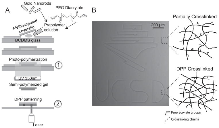
Hydrogels patterned using DPP technology were fabricated in a two-step polymerization process (Figure 1A). In the first step, a loosely-crosslinked hydrogel was made by UV photopolymerization. A prepolymer solution—consisting of 9% (v/v) PEG diacrylate (PEGDA) (MW 575 Da), 0.05% (w/v) LAP photointiator, 1 nM gold nanorods, and diH20—was administered between glass coverslips and exposed to a UV light source (350 nm, 4.5 mW cm−2) for various times (see methods for details). The UV light permits free radical polymerization through conversion of the acrylate double bonds on the PEG monomer. DPP represents the second step of polymerization. Highlighting its digital nature, a computer-generated design was applied to the stage controller and patterned within a few minutes on the hydrogel substrate (depending on the fabrication parameters and scale of the design). The resulting pattern was visualized under brightfield microscopy without the requirement of any fluorescent tags or external labeling techniques. The darker regions can be attributed to higher material density due to DPP crosslinking of the network.
Figure 1.
Process of DPP. a) Two-step process of making patterned hydrogels, with the outset showing the prepolymer constituents (gold nanorods and PEG diacrylate). A partially-crosslinked network is photopolymerized under UV light (1), followed by DPP patterning using a focused NIR laser (2), causing further crosslinking to take place. b) Digital image patterned onto the hydrogel substrate, and mechanism of crosslinking illustrated.
The mechanism of crosslinking during the two-step polymerization process is illustrated in Figure 1B. We anticipate only partial acrylate conversion in the first step thereby producing a “partially-crosslinked” soft gel that serves as a template for further mechanical patterning. We conjecture that DPP drives conversion of the remaining free acrylate bonds due to thermal crosslinking, in addition to possible physical entanglements of the PEG chains.
PEG hydrogels have traditionally been utilized in tissue engineering research for their biocompatibility, high water retention, low immunogenicity and strong molecule transport. [14,15] Additionally, PEG can be easily functionalized with cell adhesion peptides (e.g. RGD) and synthesized with a range of molecular weights and crosslinking arms, allowing for a variety of material properties tailored to a specific application and design. In this paper, while we explored relatively high-molecular weight PEGs (e.g. 10 kDa), we ultimately chose a low-molecular weight PEGDA (575 Da) to limit hydrogel swelling after the first step of polymerization and encourage thermal crosslinking in the subsequent DPP step.
During DPP, gold nanorods embedded in the hydrogel matrix were photothermally excited by a femtosecond NIR laser to mechanically pattern the substrate. The laser was directed through the objective lens (10×, NA = 0.45) and onto a motorized microscope stage where the laser beam is focused onto the sample. Based on microscopic inspection, we concluded the beam size was around ~40–50 μm in diameter and exhibited a Gaussian distribution. The beam size is a limitation of our setup, though presumably this could be further narrowed with higher magnification systems that produce a more focused laser beam. Importantly, the laser wavelength (800 nm) coincided with the longitudinal surface plasmon peak of the gold nanorods, allowing for their plasmonic enhancement (Figure 2). It has been well documented that gold nanorod absorption at their plasmon resonance produces a photothermal effect due to excitable electrons on the nanoparticle surface, releasing energy in the form of phonons. [16,17] Due to this photothermal crosslinking event, we performed the DPP step prior to any cell seeding to prevent cellular damage, a limitation of the current fabrication design.
Figure 2.
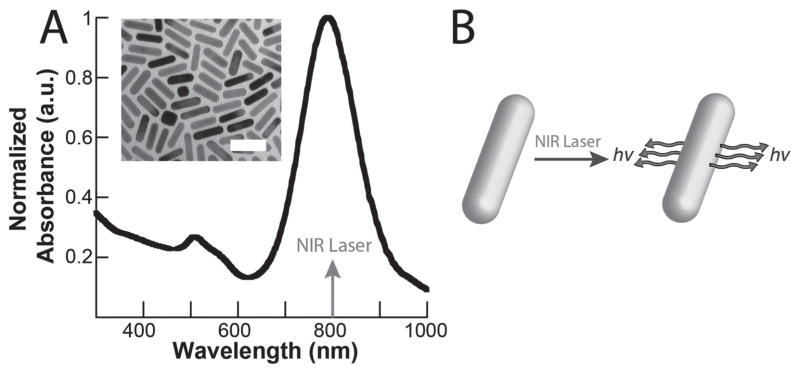
Plasmonic enhancement of gold nanorods. a) Absorbance of aqueous gold nanorod solution in relation to the laser wavelength (inset: transmission electron microscopy image of gold nanorods, scale bar = 50 nm). b) Mechanism of the photothermal effect, where the nanorods absorb near-infrared light at their surface plasmon resonance (800 nm) to produce a thermal output.
2.2. Surface Topography and Mechanical Characterization Using AFM
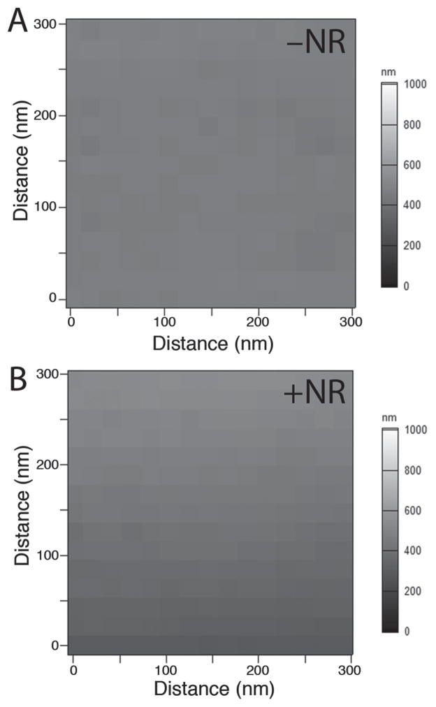
It was important to verify whether the nanorods themselves contributed to topographical features on the hydrogel substrate, which could potentially affect cell responses. AFM was used to assess the surface topography and the results are shown in Figure 3. The surface appears smooth across samples with and without nanorods, confirming that gold nanorods did not contribute to the surface nanotopography.
Figure 3.
Surface nanotopography of PEG hydrogels a) without and b) with gold nanorods, at a constant stiffness.
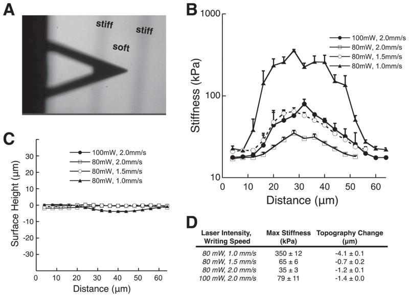
Figure 4 depicts the AFM mechanical testing of DPP hydrogel substrates. We fabricated hydrogels with a baseline stiffness of 17 kPa for mechanical patterning, though this value could be adjusted by the time of UV exposure during the first polymerization step (see Supplementary info for other baseline stiffness profiles). Laser intensity was tuned using a polarizer to achieve either 80 mW or 100 mW of average power and writing speeds were set to 1.0, 1.5 or 2.0 mm s−1 by a motorized stage controller. Figure 4A shows a microscope image of the AFM tip over the DPP stiffened regions of the hydrogel (darkened regions). Interestingly, both writing speed and laser intensity determined the degree to which the hydrogel stiffened. For instance, DPP writing criteria of 80 mW : 1.0 mm s−1, 80 mW : 1.5 mm s−1, 80 mW : 2.0 mm s−1 and 100 mW : 2.0 mm s−1 produced stiffness peaks of 350 ± 12 kPa, 65 ± 6 kPa, 35 ± 3 kPa, and 79 ± 11 kPa, with topographical changes of −4.1 ± 0.1 μm, −0.7 ± 0.2 μm, −1.2 ± 0.1 μm, and −1.37 ± 0.0 μm, respectively (Figure 4B–D). We explored another baseline stiffness of 7 kPa and have included the results in supplementary information (Figure S1). In both cases, it was observed that increasing the laser intensity or decreasing the laser writing speed produced an increase in the stiffness jump. The marginal change in topography can be attributed to a change in crosslinking density that affects the swelling of the material. By comparison, a fully crosslinked gel (prepolymer solution exposed to UV for ~10 min) produced a substrate stiffness of ~250 kPa. Thus, we believe that for stiffened regions greater than 250 kPa are a result of increased physical entanglement of the PEG chains.
Figure 4.
AFM Characterization. a) AFM tip over a patterned hydrogel substrate. AFM analysis of b) mechanical and c) topographical changes associated with DPP areas on hydrogel with various laser intensities and writing speeds. d) Quantification of max stiffness and height change from (b) and (c).
2.3. In Vitro Cellular Experiments
Employing gold nanorods with their NIR-absorbing optical properties offers an interesting avenue for crosslinking hydrogels in tissue engineering. In previous biomedical research, gold nanorods have been utilized in triggered drug delivery, hydrogel actuation, and sensing. [18–20] A concern in each case is nanorod cell toxicity. Thus, we modified the nanorod surface with PEG-thiol (a non-biofouling, nontoxic coating) and selected a concentration of PEGylated nanorods (1 nM) that minimally affects cell viability. [21]
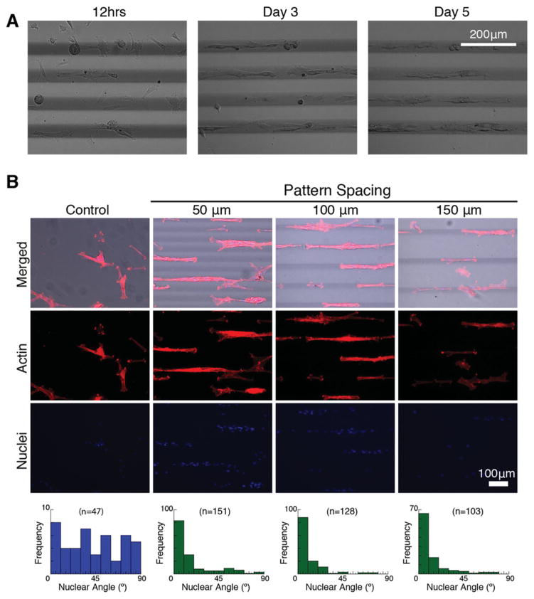
After validating the stiffness increases associated with DPP, we investigated the in vitro cellular response to the mechanical patterns. 17 kPa gels were patterned with 80 mW : 1.0 mm s−1 (which produced an increase in stiffness to 370 kPa at the peak value, as noted in Figure 4). Gels were modified with the addition of 2.5 mM PEG-RGDS for cell adhesion. A7R5 smooth muscle cells were seeded onto the gels and grown for six days. Images were taken at each day to assess migratory patterns, and on day 6, cells were fixed and stained for actin and nuclei. The timelapse images in Figure 5A suggest that cells evenly distributed initially but migrated onto the patterned areas and elongated by day 3 or 4.
Figure 5.
in vitro cell analysis. a) A7R5 smooth muscle cells show migration to the stiffer regions patterned by DPP. b) A7R5 cells stained for actin/nuclei on day 6 after incubating on DPP stiffened hydrogels with 50, 100, 150 micron spacing between the patterns. Cell alignment is quantified according to the patterned lines (0 degrees being perfectly aligned to the pattern) and compared to controls with no patterning.
Figure 5B details the actin alignment according to patterns. We chose to vary the distance between patterns, namely 50 μm, 100 μm, and 150 μm, to assess cell recruitment and alignment. 50 μm spaced-patterns showed some bridging effects between cells in close proximity and on adjacent patterns, however all patterns exhibited optimal nuclei alignment. Moreover, these data suggest that once cells migrated to the pattern, they recruited other cells to form aligned cell aggregates. It is well known that cells migrate towards stiffer regions of their substrate, a process called durotaxis. At the molecular level, cells transmit mechanical signals from their extracellular environment—in this case a patterned hydrogel—via mechanotransduction pathways and undergo migration to stiffer areas. [22] By providing a means to control substrate stiffness, DPP can be a useful platform for studying a range of molecular sensing mechanisms during durotaxis.
3. Conclusion
DPP provides a novel way to spatially and tunably pattern mechanical changes on a hydrogel substrate. It allows the user to modulate stiffness according to laser intensity, writing speed and any digital pattern, thus providing enhanced flexibility in hydrogel design without the requirement of multiple polymer solutions or physical masks. DPP could be employed in various facets of tissue engineering, such as for studying tissue mechanics in governing cell fate (e.g. stem cell differentiation, migration, and proliferation). More generally, the platform could be used on a variety of temperature-sensitive materials for the effect of altering scaffold mechanics (via thermal crosslinking or degradation). Patterning resolution could also be optimized with the appropriate automated stage and light configuration (e.g. ultra-focused laser). With its versatility and adaptability, DPP can be a potentially useful tool for mechanically patterning hydrogels in a designer fashion.
4. Experimental Section
Materials
For gold nanorod synthesis and modification, hydrochloroauric acid (HAuCl4), silver nitrate (AgNO3), sodium borohydride, and L-ascorbic acid were purchased from Sigma-Aldrich and cetyltrimethylammonium bromide (CTAB) was purchased from CalBioChem (EMD Millipore). Milli-Q water (18.2 Ω, MilliPore) was used in all synthesis steps. mPEG-thiol (5 kDa) (Nanocs) was used in nanorod surface modification. For pre-polymer solution, poly(ethylene glycol)diacrylate (PEGDA) (575 Da, Sigma), Milli-Q H2O (Milli-Pore), and lithium phenyl-2,4,6-trimethylbenzoylphosphinate (LAP) photoinitiator [23] were used. Acryloyl-PEG-RGDS was synthesized according to previous protocols. [24]
Digitial Plasmonic Patterning
Hydrogels patterned by DPP were made in a two-step polymerization process. First, a prepolymer solution was photopolymerized with UV light, creating a partially polymerized hydrogel network. Second, a focused NIR laser was used to crosslink the network further. Gold nanorods (average length = 33.2 ± 3.0 nm, width = 9.5 ± 1.1 nm, aspect ratio = 3.5 ± 0.5) were synthesized according to a general wet chemical synthesis and surface modified with PEG-SH to reduce cytotoxicity. [25,26] A prepolymer solution was made consisting of 9% (v/v) poly(ethylene glycol) diacrylate (MW 575 Da), 1 nM gold nanorods, and 0.05% (w/v) LAP photoinitiator in diH2O. The solution was pipetted between two glass slides and a cover slip spacer (#1 thickness, Chemglass), where one side was methacrylated glass for chemical linkage to the hydrogel and the other side was coated with dichlorodimethylsilane (DCDMS), a hydrophobic monolayer to allow easy hydrogel removal. The solution was exposed to UV light (350 nm, 4.5 mW cm−2, UVP) for 10 or 12 s to produce partially crosslinked gels with stiffness measurements of 7 kPa or 17 kPa, respectively. Gels were incubated in diH2O for several days to remove any unreacted materials from the gel, then placed on a glass coverslip with 25 μL fresh diH2O and secured to an automatic stage atop an inverted microscope. Patterning via DPP occurred when a femtosecond laser beam (800 nm, 80 MHz, Coherent) was focused through the laser objective lens (10×, NA 0.45) and onto the gel sample. Patterns were drawn according to a digital mask designed on the computer and relayed to the stage controller (MS2000, ASI) for controlled writing speed (mm/s).
AFM Analysis: Mechanical and Topographical Testing
Stiffness of the hydrogel was confirmed by atomic force microscopy (AFM; MFP3D, Asylum Research) as detailed previously. [8,27] Briefly, a pyramidal probe, 0.08 N m−1 spring constant with a 35° half angle (PNP-TR20, Nanoworld), was used to indent a substrate every 10 μm in triplicate over two repeats of the low/high pattern stripes. The probe indentation velocity was fixed at 2 μm/s with the trigger force of 2 nN. Elastic modulus maps were determined by the Hertz cone model with a sample Poisson ratio of 0.5 fit over a range of 10 to 90% indentation force. [27] Surface height is also simultaneously computed based on when probe deflection occurs as it indents the material. AFM software (Igor pro 6.22) was applied to generate the stiffness and analyze height data.
In vitro Cell Studies
Prepolymer solution was modified with 2.5 mM acryloyl-PEG-RGDS prior to the first crosslinking step to facilitate cell attachment to the hydrogels. Gels were patterned by DPP with 80 mW of laser power and 1.0 mm s−1 writing speed, and were subsequently exposed to 2% Penn/strep in PBS for several days in a 24-well plate followed by 1 h of UV-exposure (cell culture hood) for sterilization. A7R5 smooth muscle cells were cultured in Dulbecco’s Modified Eagle’s Medium with 10% FBS, trypsinized, and seeded at a cell density of 25,000 cells mL−1 into each well. Media was exchanged every two days. Images were captured at various timepoints (up to six days) using DIC microscopy. Cells were fixed on day 6 with 4% paraformaldehyde and stained for actin and nuclei with rhodamine phalloidin and DAPI fluorescent dyes, respectively. Fluorescent images were captured with a Leica fluorescent microscope and analyzed for cell distributions and alignment (determined by the long axis of the nuclei) using ImageJ computer software.
Supplementary Material
Acknowledgments
We greatly appreciate the support from the National Science Foundation (grants CMMI-1130894, CMMI-1332681), the National Institute of Health (NIH DP02 OD006460), and UCSD Neuroscience Microscopy Shared Facility Grant P30 NS047101. We would like to thank Dr. Marilyn Farquhar for the use of the electron microscopy facility at UCSD, and Timo Meerloo for electron microscopy sample preparation. We would also like to thank Dr. Xin Qu (UC San Diego) and Professor Jason Burdick (University of Pennsylvania) for helpful discussions.
Footnotes
Supporting Information is available from the Wiley Online Library or from the author.
Contributor Information
Kolin C. Hribar, Department of NanoEngineering, University of California, San Diego, La Jolla, CA 92093–0448, USA
Yu Suk Choi, Department of Bioengineering, University of California, San Diego, La Jolla, CA 92037, USA. Kolling Institute of Medical Research, University of Sydney, Sydney, Australia.
Matthew Ondeck, Materials Science and Engineering Program, University of California, San Diego, La Jolla, CA 92093, USA.
Adam J. Engler, Department of Bioengineering, University of California, San Diego, La Jolla, CA 92037, USA
Shaochen Chen, Email: chen168@eng.ucsd.edu, Department of NanoEngineering, University of California, San Diego, La Jolla, CA 92093–0448, USA.
References
- 1.Nie Z, Kumacheva E. Nature Mater. 2008;7:277. doi: 10.1038/nmat2109. [DOI] [PubMed] [Google Scholar]
- 2.Dvir T, Timko BP, Kohane DS, Langer R. Nature Nanotechnol. 2011;6:13. doi: 10.1038/nnano.2010.246. [DOI] [PMC free article] [PubMed] [Google Scholar]
- 3.Kloxin AM, Kasko AM, Salinas CN, Anseth KS. Science. 2009;324:59. doi: 10.1126/science.1169494. [DOI] [PMC free article] [PubMed] [Google Scholar]
- 4.Atala A, Kasper FK, Mikos AG. Sci Trans Med. 2012;4:160rv12. doi: 10.1126/scitranslmed.3004890. [DOI] [PubMed] [Google Scholar]
- 5.Lutolf MP, Hubbell JA. Nat Biotechnol. 2005;23:47. doi: 10.1038/nbt1055. [DOI] [PubMed] [Google Scholar]
- 6.Engler AJ, Sen S, Sweeney HL, Discher DE. Cell. 2006;126:677. doi: 10.1016/j.cell.2006.06.044. [DOI] [PubMed] [Google Scholar]
- 7.Engler A, Bacakova L, Newman C, Hategan A, Griffin M, Discher D. Biophys J. 2004;86:617. doi: 10.1016/S0006-3495(04)74140-5. [DOI] [PMC free article] [PubMed] [Google Scholar]
- 8.Choi YS, Vincent LG, Lee AR, Kretchmer KC, Chirasatitsin S, Dobke MK, Engler AJ. Biomaterials. 2012;33:6943. doi: 10.1016/j.biomaterials.2012.06.057. [DOI] [PMC free article] [PubMed] [Google Scholar]
- 9.Guvendiren M, Burdick JA. Nature Commun. 2012;3:792. doi: 10.1038/ncomms1792. [DOI] [PubMed] [Google Scholar]
- 10.Lo CM, Wang HB, Dembo M, Wang YL. Biophys J. 2000;79:144. doi: 10.1016/S0006-3495(00)76279-5. [DOI] [PMC free article] [PubMed] [Google Scholar]
- 11.Isenberg BC, Dimilla PA, Walker M, Kim S, Wong JY. Biophys J. 2009;97:1313. doi: 10.1016/j.bpj.2009.06.021. [DOI] [PMC free article] [PubMed] [Google Scholar]
- 12.Vincent LG, Choi YS, Alonso-Latorre B, del Alamo JC, Engler AJ. Biotechnol J. 2013;8:472. doi: 10.1002/biot.201200205. [DOI] [PMC free article] [PubMed] [Google Scholar]
- 13.Pathak A, Kumar S. Proc Natl Acad Sci USA. 2012;109:10334. doi: 10.1073/pnas.1118073109. [DOI] [PMC free article] [PubMed] [Google Scholar]
- 14.Peppas NA, Hilt JZ, Khademhosseini A, Langer R. Adv Mater. 2006;18:1345. [Google Scholar]
- 15.Lin CC, Anseth KS. Pharm Res. 2009;26:631. doi: 10.1007/s11095-008-9801-2. [DOI] [PMC free article] [PubMed] [Google Scholar]
- 16.Link S, El-Sayed MA. J Phys Chem B. 1999;103:8410. [Google Scholar]
- 17.Link S, El-Sayed MA. Int Rev Phys Chem. 2000;19:409. [Google Scholar]
- 18.Hribar KC, Metter RB, Ifkovits JL, Troxler T, Burdick JA. Small. 2009;5:1830. doi: 10.1002/smll.200900395. [DOI] [PMC free article] [PubMed] [Google Scholar]
- 19.Hribar KC, Lee MH, Lee D, Burdick JA. ACS Nano. 2011;5:2948. doi: 10.1021/nn103575a. [DOI] [PubMed] [Google Scholar]
- 20.Huang X, El-Sayed IH, Qian W, El-Sayed MA. J Am Chem Soc. 2006;128:2115. doi: 10.1021/ja057254a. [DOI] [PubMed] [Google Scholar]
- 21.Grabinski C, Schaeublin N, Wijaya A, D’Couto H, Baxamusa SH, Hamad-Schifferli K, Hussain SM. ACS Nano. 2011;5:2870. doi: 10.1021/nn103476x. [DOI] [PubMed] [Google Scholar]
- 22.Holle AW, Engler AJ. Curr Op Biotechnol. 2011;22:648. doi: 10.1016/j.copbio.2011.04.007. [DOI] [PMC free article] [PubMed] [Google Scholar]
- 23.Fairbanks BD, Schwartz MP, Bowman CN, Anseth KS. Biomaterials. 2009;30:6702. doi: 10.1016/j.biomaterials.2009.08.055. [DOI] [PMC free article] [PubMed] [Google Scholar]
- 24.Hahn MS, Taite LJ, Moon JJ, Rowland MC, Ruffino KA, West JL. Biomaterials. 2006;27:2519. doi: 10.1016/j.biomaterials.2005.11.045. [DOI] [PubMed] [Google Scholar]
- 25.Sau TK, Murphy CJ. Langmuir. 2004;20:6414. doi: 10.1021/la049463z. [DOI] [PubMed] [Google Scholar]
- 26.Liao HW, Hafner JH. Chem Mater. 2005;17:4636. [Google Scholar]
- 27.Radmacher M. Method Cell Biol. 2007;83:347. doi: 10.1016/S0091-679X(07)83015-9. [DOI] [PubMed] [Google Scholar]
Associated Data
This section collects any data citations, data availability statements, or supplementary materials included in this article.


