

Abstract
Here we demonstrate a method for creating multilayer or 3D microfluidics by casting a curable resin around a water-soluble, freestanding sacrificial mold. We use a purpose-built 3D printer to pattern self-supporting filaments of the sugar alcohol isomalt, which we then back-fill with a transparent epoxy resin. Dissolving the sacrificial mold leaves a network of cylindrical channels as well as input and output ports. We use this technique to fabricate a combinatorial mixer capable of producing 8 combinations of two fluids in ratios ranging from 1 : 100 to 100 : 1. This approach allows rapid iteration on microfluidic chip design and enables the use of geometry and materials not accessible using conventional soft lithography. The ability to precisely pattern round channels in all three dimensions in hard and soft media may prove enabling for many organ-on-chip systems.
Introduction
Most microfluidic devices are made by bonding one or more layers of molded polydimethylsiloxane (PDMS). PDMS, though versatile, is incompatible with high pressures and some organic solvents.1 For these applications, glass and polymer microfluidics can be fabricated by embossing, injection molding, and laser or X-ray ablation.1,2 However, these methods are generally similar to soft lithography in that they produce open channels with a fixed depth and vertical walls that are closed by bonding to a substrate. The bonding process requires precise alignment, so that the fabrication time and the probability of a leak scale with the number of layers bonded. The bonding problem may be avoided by using techniques for creating monolithic multilayer devices, of which there are four: two-photon femtosecond laser micromachining, direct 3D-printing, fugitive ink deposition, and sacrificial molding.
Femtosecond micromachining allows the ablation of transparent polymers at a focal point within their volume. It has resolution on the order of nanometers, but, like 3D printing, is an inherently serial process. Fabrication time is proportional to channel volume, and the depth of features that can be machined is limited by the working distance of the objective.3 Femtosecond lasers are also quite expensive, which has likely limited their use in academic settings for the development of microfluidics.
Layer-by-layer 3D printing of microfluidic devices was demonstrated at least as early as 2005.4 Reports of 3D-printed microfluidic devices have increased over the past few years5–13 and can be attributed in part to improvements in the cost, performance, and availability of 3D printers and 3D printing services. Commercial layer-by-layer printers can achieve resolution on the order of tens of microns, but printing at higher resolution generally requires a more expensive printer and a longer build time.14 Also, the resolution specification is not necessarily equal to the minimum buildable channel dimension. For example, Au et al.9 found that channels less than 400 μm wide fabricated via stereolithography could not reliably be cleared of resin. Although layer-by-layer printing can be performed with many different materials, including hydrogels,15 3D printing services offer a limited choice of materials, which may lack the mechanical, chemical, and optical properties required for any given application.
3D microfluidics can also be fabricated via fugitive ink deposition, in which filaments of a sacrificial “fugitive” ink are extruded through a nozzle into a fluid reservoir. After the printing process is complete, the reservoir is cured and the ink is removed via suction. Wax16–19 and hydrogel20–22 fugitive inks have been used for applications in microfluidic and tissue engineering. Although these inks can be extruded at room temperature, their low stiffness means that cantilevered or spanning filaments require a supporting fluid reservoir.
Sacrificial molding is conceptually similar to fugitive ink deposition but uses a stiff material, so that the construct can be built without the support of a liquid reservoir. Miller et al. recently demonstrated the use of a modified 3D printer to pattern a lattice of sacrificial carbohydrate glass, which was then used as a sacrificial mold to create vascular channels in a variety of cell-laden gels.23 It is apparent from videos of the process24 that due to the high feed rate and flow rate, the filaments did not cool immediately upon exiting the nozzle, but drooped until they rested on the substrate or on previously printed filaments. All of the printed filaments started and ended on the substrate, and there was no demonstration that filaments could be branched (started from existing filaments) or cantilevered. We show that by precisely controlling the temperature and extrusion pressure and using a low feed rate, it is possible to pattern filaments of a carbohydrate glass along 3D paths with minimal drooping and bleeding of the material. New filaments can originate from existing filaments and can terminate at existing filaments or in free space, forming a cantilever. The diameter can be controlled by varying the rate of extrusion relative to the rate of translation, and input and output ports can be formed directly as part of the build process. Thus, we show that sacrificial molding of a 3D-printed construct is a practical method for creating monolithic microfluidic devices with controlled flows in media that can be cast at low temperatures.
Materials and methods
Preparation of carbohydrate glass
For our sacrificial mold we used isomalt (galenIQ 990, Beneo-Palatinit GmbH), a sugar alcohol commonly used as an artificial sweetener. When cooled rapidly to below its glass transition temperature of 55 °C, isomalt forms a stiff, optically clear glass that is resistant to recrystallization.25 Crystallization can be further inhibited by reducing the water content.26 We found that isomalt boiled to 195 °C resisted crystallization in the extruder during the printing process. The flexural modulus of cast isomalt samples was measured using a 4-point bending test and found to be 2.6 GPa (ESI† Table S1).
Generator design
The structure of our mixture generator is similar to that given by Walker et al.27 The geometry and equivalent circuit of the mixture generator are shown in Fig. 1. The two components of each mixture originate from a feed channel and pass through a throttling channel before meeting at the output channel.
Fig. 1.

(a) Equivalent circuit of the mixture generator. (b) Molding process. (c) Dye-filled channels. (d) Cut-away view showing round channel cross-section.
The resistances and the net flow through all of the output channels are set equal, so the pressure drop between the inlet and the meeting of each throttling channel is also equal. Under this condition, at each bifurcation of each feed channel, the ratio of the output flow Qout and the downstream flow Qi − Qn is determined by the resistance of the throttling channel Rn and the effective downstream resistance. The resistance of the feed channel between bifurcations is constant and assigned a value of 1. Therefore,
| (1) |
| (2) |
Solving for Rn+1,
| (3) |
Qn and Qi are known. R0 must be chosen such that none of the computed resistances are negative. The relationship between diameter, length, and resistance in a round tube under laminar flow conditions (i.e., Poiseuille flow) is given by
| (4) |
Using this relationship, we selected R0 such that the smallest diameter used in the design was 25% of the largest diameter. Thus, the feed channels were 1 mm in diameter while the smallest throttling channel was 250 μm in diameter. The mixing ratios were chosen to be 100 : 1, 31.6 : 1. 10 : 1, 3.16 : 1, and their reciprocals.
CAD processing
The AutoCAD .dxf file was parsed by purpose-written scripts into a set of toolpaths, defined as a sequence of XYZ coordinates to be passed at prescribed times. The order in which to print the filaments must satisfy two conditions: each printed filament must start either on the substrate or an existing filament, and no path traversed by the nozzle can collide with an existing filament. The simplicity of the design allowed us to choose the printing order manually, though it is also possible to choose the order algorithmically.
Diameter calibration
For any given volumetric flow rate Q, the diameter of a cylindrical filament is given by the conservation of mass relation
| (5) |
where D is the diameter and v is the feed rate. Under laminar flow conditions, Q is directly proportional to the pressure drop across the nozzle and inversely proportional to the fluid viscosity.28 Therefore,
| (6) |
where Pn is pressure inside the nozzle, Pf the pressure inside the filament at the nozzle exit, and η the fluid viscosity. Pf and η are dependent upon temperature and, as we discuss later, the spatiotemporal temperature profile of an extruded filament is dependent upon diameter. This means that diameter cannot be calculated based on feed rate alone. In order to determine what feed rate should be applied to achieve each design diameter, we printed a series of horizontal filaments at different feed rates and measured the diameter optically. Images were acquired at 5× magnification on a light microscope (Axio Imager, Zeiss). The line detection utility in the LabVIEW Vision package (National Instruments) was used to fit a line to either edge of the channel, and the distance between lines was taken as the filament diameter. The feed rate for each channel within the device was determined by fitting a cubic spline to the calibration points and interpolating the feed rate values for the desired diameters. These calibration points are shown in Fig. 2(a).
Fig. 2.
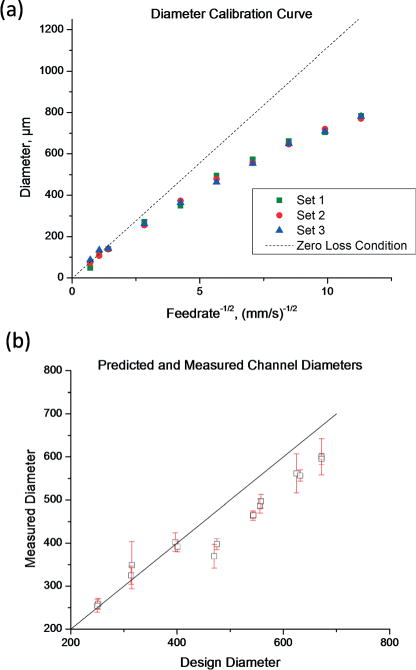
(a) Relationship between feed rate and filament diameter. The zero loss condition is a linear fit to the data points where the filament diameter is less than the nozzle diameter. (b) Comparison of predicted and measured channel diameters (R2 = 0.95).
Printing
The printer was custom-built using precision stages (Aerotech ANT-160, ATS-100) and a heated piston-style extruder. Extrusion pressure was monitored using a hot-melt transducer (MPI MN207) and used in a servo loop to control the piston position. The use of pressure feedback in conjunction with a low-compliance piston extruder allows pressure to be applied and removed very quickly—within 250 ms (ESI† Fig. S4). By using a very low flow rate and a very fast means of turning the flow on and off, deposition of unwanted material is minimized. This closed-loop pressure feedback is essential to precise flow control and, to our knowledge, has not been implemented on any commercial or previously reported 3D printers. The details of this pressure control scheme are provided in the ESI.†
The extruder temperature was set to 115 °C. In order to facilitate adhesion to the substrate, the X–Y stage was heated to 60 °C, near the glass transition temperature of isomalt, when printing the filaments attached to the substrate. For the generator shown, we used a tapered 150 μm nickel–silver micronozzle (Subrex) and an extrusion pressure of 25 psi. Printing took about one hour. Video from a camera aligned with the printer Y axis showed that filaments drooped less than 200 μm below the nozzle during printing.
Epoxy casting
The printed mold was inverted and placed in a flexible silicone cavity. Epoxy resin (EpoxAcast, Smooth-On) was mixed and poured into the mold so that it wet the glass substrate. After curing overnight, isomalt was removed from the cured construct under via dissolution in water. Dissolution was complete after immersion in still water at room temperature for 36 hours, sonication in water at 41 °C for 16 hours, or immersion in boiling water for 3 hours.
Agarose casting
Preliminary experiments showed that immersion of isomalt in aqueous solutions resulted in dissolution within seconds or minutes. In order to preserve the channels long enough for the gel to set, we coated the mold with a thin layer of polycaprolactone. Polycaprolactone (Mn 80 000, Sigma-Aldrich) was dissolved at 5% w/v in dichloromethane. The mold was dipped in this solution and removed, depositing a thin film of polycaprolactone around the isomalt. A 3% agarose gel was then cast around the mold. The channels were clear of isomalt within 30 minutes of casting.
Channel dimensions
The finished device was filled with food dye and imaged at 5× magnification a light microscope (Axio Imager, Zeiss). In order to capture variation in the channel diameters, the caliper function in the LabVIEW Vision development kit was used to measure the distance between edges for each row of pixels perpendicular to each channel.
Device performance
The performance of the epoxy mixture generator was measured using aqueous solutions of two dyes, tetrazine and Coomassie brilliant blue R-250 (Sigma-Aldrich) Fig. 3. A syringe pump (Fusion 200, Chemyx) was used to pump the two dyes through the device and the outputs were collected in acrylic cuvettes (Brand Tech Scientific). Optical absorbance values between 275 and 750 nm were measured using a UV-visible spectrometer (GeneQuant 1300, General Electric). The ratio of the tetrazine solution to the Coomassie blue solution for each output was determined by minimizing the squared error for the over-constrained system of equations
| (7) |
where x is the proportion of tetrazine solution, ai is the absorbance of tetrazine, bi is the absorbance of Coomassie blue, and ci is the absorbance of the output at wavelength i.
Fig. 3.
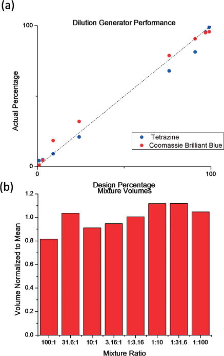
(a) Dilution generator performance (R2 = 0.99). (b) Volume of each mixture collected, normalized to the mean of 800 μL. The standard deviation is 10.5%.
Results
The calibration curve for the relationship between pressure and feed rate is shown in Fig. 2(a). Based on eqn (5), a constant flowrate Q would result in a straight line on the plot of D against v(−1/2). This “zero-loss condition” can be estimated by applying a linear fit to the data points for which the filament diameter is less than the nozzle diameter. For filament diameters greater than the nozzle diameter, Q decreases monotonically with D. This can be explained as follows.
The extruder pressure Pn is precisely controlled by a servo loop and can be regarded as independent of any other variables. Temperature, however, is controlled using a sensor on the surface of the extruder, and the temperature near the nozzle exit is not equal to the temperature measured by this sensor. The dependence of Q on D can be explained in part through the effect of temperature on Pf and η.
The nozzle loses heat via conduction to the filament, and a thicker filament will remove heat faster than a thin filament. This causes a local temperature decrease at the nozzle tip, which is effectively invisible to the temperature controller. The viscosity η of isomalt increases exponentially with temperature.29 Therefore, a slight decrease in temperature at the nozzle tip would decrease Q and therefore decrease D. This explanation assumes that conduction, not convection, is the dominant mode of heat transfer.
Pf, the pressure inside the filament, can be attributed to surface tension γ, and is inversely related to diameter.
| (8) |
Although thicker filaments have larger radii of curvature, they are also subject to more rapid cooling via conduction down the filament and free convection from the surface. Surface tension for most materials decreases with temperature. Thus, a thick filament might exhibit increased Pf relative to a thin filament due to a much cooler surface.
The agreement between predicted and measured channel diameters is shown in Fig. 2(b). As is apparent in Fig. 1(c), we found that the diameter of the channels became smaller near the channel junctions. For shorter channels, this would be expected to decrease the average diameter and restrict flow. Indeed, the shortest channels, designed to be 2 mm long and about 475 μm in diameter, showed the greatest negative deviation from the design diameter.
Channels of similar design dimensions had very similar measured diameters, and the deviation from the design diameters became more negative at higher diameters. This suggests some systematic error, which may be due to slight changes in material properties. Crystallization or degradation due to extended time in the extruder and differences in the water content of the isomalt feedstock are two factors that could influence the material rheology and cause time- or batch- dependent changes in the relationship between feed rate and diameter.
The performance of the epoxy mixture generator is shown in Fig. 2(a). The device achieved good linearity over the entire range of operation (R2 = 0.9925). The volume of each mixture collected is shown in Fig. 2(b). The deviation from the design values can be attributed to the error in the channel diameters and neglect of bending losses in the design calculation. Bending losses in microfluidic devices increase monotonically with mass flow rate.30 For a larger channel with lower frictional (major) losses, bending (minor) losses will constitute a larger proportion of the total pressure loss. The net effect would be to decrease the relative flow through larger channels, causing error in the output ratios such that they are closer to 1 : 1. This is consistent with the data, but is easily explained by error in the channel diameters themselves as well.
Discussion
We have demonstrated a means of fabricating free-standing, 3D, branched and cantilevered filament networks using a stiff, water-soluble, biocompatible material. An immediate application of this process is monolithic microfluidic devices, for which it offers advantages in certain applications. For example, cylindrical channels minimize the channel surface area for any given volume, limiting adsorption to the channel walls. Hydrodynamic focusing is more easily implemented in round channels than rectangular channels and allows confinement of suspended analytes like cells to a small region within the center of the channel.31 The fixed channel height inherent in lamination-based processes limits the range of channel resistance per unit length; thus, microfluidic mixture and dilution generators can require very long, serpentine channels in order to achieve a large range of mixing ratios.32 This process, which can produce channels with a resistance per unit length spanning at least 4 orders of magnitude, can simplify the design of such devices and reduce their 2D footprint. The device presented here can be reconfigured to produce different mixing ratios by changing only the diameters, with no need to change the topology.
Sacrificial molding can create complex networks of round channels in a variety of media, which may prove useful for recapitulating physiological flows, stresses, and strains. Sacrificial molds can also be dissolved very quickly in hydrogels, enabling rapid perfusion of large constructs before hypoxia occurs. A potential pitfall, however, is the effect of dissolved mold material on encapsulated cells. We found that isomalt filaments with diameters on the order of 100 μm dissolve completely in seconds to minutes, requiring the application of a thin layer of polylactide or polycaprolactone to the sacrificial mold in order to preserve the cylindrical channels while the gel sets. However, polylactide and polycaprolactone are permeable to water.33 Using an epoxy matrix, we found that immersion in water at room temperature required 36 hours to clear the carbohydrate glass. The same glass clears in less than 30 minutes when coated in polycaprolactone and cast in agarose. We take this as evidence that isomalt diffuses through the polymer layer, whereas the agarose or other gelling agent does not. This allows for very rapid perfusion of vascularized constructs; however, if the volume of the vasculature is sufficiently large relative to the total volume of the construct, the resulting large concentration of sugars or sugar alcohols could have toxic effects. Using a soluble material of higher molecular weight, such as polyvinyl alcohol or thermoplastic starch, could reduce the potential metabolic effects of large concentrations of sugars and sugar alcohols.
Conclusions
In summary, we have demonstrated that 3D printing of the water-soluble sugar alcohol isomalt enables the facile fabrication of 3D branching cylindrical channels in monolithic microfluidic devices. This may find application in the rapid prototyping of chips for synthetic and analytical chemistry as well as in tissue engineering, where there is often a need to fabricate cylindrical microchannels in soft media.
Supplementary Material
Acknowledgments
M. K. Gelber was supported by fellowships from the Roy G. Carver Foundation and the Arnold and Mabel Beckman Foundation. We gratefully acknowledge the gift of isomalt and advice on its processing provided by Mr. Oliver Luhn of Südzucker AG/Beneo-Palatinit GmbH. The development of the printer was supported by the Beckman Institute for Advanced Science and Technology via its seed grant program. Device fabrication was partially supported by the National Institutes of Health via grant number 2R01EB009745.
Footnotes
Electronic supplementary information (ESI) available. See DOI: 10.1039/c4lc01392a
Notes and references
- 1.Sollier E, Murray C, Maoddi P, Di Carlo D. Lab Chip. 2011;11:3752–3765. doi: 10.1039/c1lc20514e. [DOI] [PubMed] [Google Scholar]
- 2.Beebe DJ, Mensing GA, Walker GM. Annu Rev Biomed Eng. 2002;4:261–286. doi: 10.1146/annurev.bioeng.4.112601.125916. [DOI] [PubMed] [Google Scholar]
- 3.Gattass RR, Mazur E. Nat Photonics. 2008;2:219–225. [Google Scholar]
- 4.Kang H-W, Lee IH, Cho D-W. J Eng Ind. 2005;126:766–771. [Google Scholar]
- 5.Kitson PJ, Rosnes MH, Sans V, Dragone V, Cronin L. Lab Chip. 2012;12:3267–3271. doi: 10.1039/c2lc40761b. [DOI] [PubMed] [Google Scholar]
- 6.Anderson KB, Lockwood SY, Martin RS, Spence DM. Anal Chem. 2013;85:5622–5626. doi: 10.1021/ac4009594. [DOI] [PubMed] [Google Scholar]
- 7.Waldbaur A, Carneiro B, Hettich P, Wilhelm E, Rapp B. Microfluid Nanofluidics. 2013:1–11. doi: 10.1007/s10404-013-1177-x. [DOI] [Google Scholar]
- 8.Comina G, Suska A, Filippini D. Lab Chip. 2014;14:424–430. doi: 10.1039/c3lc50956g. [DOI] [PubMed] [Google Scholar]
- 9.Au AK, Lee W, Folch A. Lab Chip. 2014;14:1294–1301. doi: 10.1039/c3lc51360b. [DOI] [PMC free article] [PubMed] [Google Scholar]
- 10.Lee KG, Park KJ, Seok S, Shin S, Kim DH, Park JY, Heo YS, Lee SJ, Lee TJ. RSC Adv. 2014;4:32876–32880. [Google Scholar]
- 11.Erkal JL, Selimovic A, Gross BC, Lockwood SY, Walton EL, McNamara S, Martin RS, Spence DM. Lab Chip. 2014;14:2023–2032. doi: 10.1039/c4lc00171k. [DOI] [PMC free article] [PubMed] [Google Scholar]
- 12.Bhargava KC, Thompson B, Malmstadt N. Proc Natl Acad Sci U S A. 2014;111:15013–15018. doi: 10.1073/pnas.1414764111. [DOI] [PMC free article] [PubMed] [Google Scholar]
- 13.Moore J, McCuiston A, Mittendorf I, Ottway R, Johnson RD. Microfluid Nanofluid. 2011;10:877–888. [Google Scholar]
- 14.Neill PF, Ben Azouz A, Vázquez M, Liu J, Marczak S, Slouka Z, Chang HC, Diamond D, Brabazon D. Biomicrofluidics. 2014;8:052112. doi: 10.1063/1.4898632. [DOI] [PMC free article] [PubMed] [Google Scholar]
- 15.Chan V, Zorlutuna P, Jeong JH, Kong H, Bashir R. Lab Chip. 2010;10:2062–2070. doi: 10.1039/c004285d. [DOI] [PubMed] [Google Scholar]
- 16.Therriault D, White SR, Lewis JA. Nat Mater. 2003;2:265–271. doi: 10.1038/nmat863. [DOI] [PubMed] [Google Scholar]
- 17.Dharmatilleke S, Henderson HT, Bhansali S, Ahn CH. Proc SPIE 4177, Microfluidic Devices and Systems III. 2000;83 [Google Scholar]
- 18.Toohey KS, Sottos NR, Lewis JA, Moore JS, White SR. Nat Mater. 2007;6:581–585. doi: 10.1038/nmat1934. [DOI] [PubMed] [Google Scholar]
- 19.Hansen CJ, Wu W, Toohey KS, Sottos NR, White SR, Lewis JA. Adv Mater. 2009;21:4143–4147. [Google Scholar]
- 20.Wu W, DeConinck A, Lewis JA. Adv Mater. 2011;23:H178–H183. doi: 10.1002/adma.201004625. [DOI] [PubMed] [Google Scholar]
- 21.Bertassoni LE, Cecconi M, Manoharan V, Nikkhah M, Hjortnaes J, Cristino AL, Barabaschi G, Demarchi D, Dokmeci MR, Yang Y, Khademhosseini A. Lab Chip. 2014;14:2202–2211. doi: 10.1039/c4lc00030g. [DOI] [PMC free article] [PubMed] [Google Scholar]
- 22.Kolesky DB, Truby RL, Gladman AS, Busbee TA, Homan KA, Lewis JA. Adv Mater. 2014;26:3124–3130. doi: 10.1002/adma.201305506. [DOI] [PubMed] [Google Scholar]
- 23.Miller JS, Stevens KR, Yang MT, Baker BM, Nguyen DHT, Cohen DM, Toro E, Chen AA, Galie PA, Yu X, Chaturvedi R, Bhatia SN, Chen CS. Nat Mater. 2012;11:768–774. doi: 10.1038/nmat3357. [DOI] [PMC free article] [PubMed] [Google Scholar]
- 24.Evan Lerner KS. Printing 3D Blood Vessel Networks out of Sugar. http://www.upenn.edu/spotlights/rep-rap-3d-printing-blood-vessel-networks, Accessed September 17, 2014.
- 25.Borde B, Cesàro A. J Therm Anal Calorim. 2002;69:267–280. [Google Scholar]
- 26.Cammenga HK, Zielasko B. Ber Bunsen-Ges. 1996;100:1607–1609. [Google Scholar]
- 27.Walker GM, Monteiro-Riviere N, Rouse J, O’Neill AT. Lab Chip. 2007;7:226–232. doi: 10.1039/b608990a. [DOI] [PubMed] [Google Scholar]
- 28.Munson BR, Young DF, Okiishi TH. Fundamentals of Fluid Mechanics. J Wiley & Sons; New York: 1990. [etc.] [Google Scholar]
- 29.Raudonus J, Bernard J, Janßen H, Kowalczyk J, Carle R. Food Res Int. 2000;33:41–51. [Google Scholar]
- 30.Yuk Kwan Lee S, Wong M, Zohar Y. IEEE International Conference on Micro Electro Mechanical Systems – MEMS. 2001:491494. [Google Scholar]
- 31.Paie P, Bragheri F, Vazquez RM, Osellame R. Lab Chip. 2014;14:1826–1833. doi: 10.1039/c4lc00133h. [DOI] [PubMed] [Google Scholar]
- 32.Lee K, Kim C, Kim Y, Jung K, Ahn B, Kang J, Oh K. Biomed Microdevices. 2010;12:297–309. doi: 10.1007/s10544-009-9385-6. [DOI] [PubMed] [Google Scholar]
- 33.Shogren R. J Environ Polym Degrad. 1997;5:91–95. [Google Scholar]
Associated Data
This section collects any data citations, data availability statements, or supplementary materials included in this article.