Abstract
Core-shell hybrid nanoparticles (NPs) for drug delivery have attracted numerous attentions due to their enhanced therapeutic efficacy and good biocompatibility. In this work, we fabricate a two-stage microfluidic chip to implement a high-throughput, one-step, and size-tunable synthesis of mono-disperse lipid-poly (lactic-co-glycolic acid) NPs. The size of hybrid NPs is tunable by varying the flow rates inside the two-stage microfluidic chip. To elucidate the mechanism of size-controllable generation of hybrid NPs, we observe the flow field in the microchannel with confocal microscope and perform the simulation by a numerical model. Both the experimental and numerical results indicate an enhanced mixing effect at high flow rate, thus resulting in the assembly of small and mono-disperse hybrid NPs. In vitro experiments show that the large hybrid NPs are more likely to be aggregated in serum and exhibit a lower cellular uptake efficacy than the small ones. This microfluidic chip shows great promise as a robust platform for optimization of nano drug delivery system.
I. INTRODUCTION
Core-shell type hybrid nanoparticles (NPs) for drug delivery have been widely investigated for their improved therapeutic efficacy and enhanced biocompatibility.1–4 The drugs can be encapsulated in the core-region and the lipid shell provides a possibility of surface modification.5,6 Lipid-shell poly (lactic-co-glycolic acid) (PLGA)-core NPs have attracted particular attention as an ideal delivery system for several reasons. (1) The PLGA core can keep the structure stable during the systemic circulation.7 (2) The loaded drugs can be released from PLGA cores in a controlled and sustained manner.8,9 (3) The lipid shell can keep the NP stealth during the circulation.10 (4) The whole structure of NP is rigid, which can enhance the cellular uptake as well as the biological effects.11,12 However, to develop an efficient nano-drug delivery system, the size distribution of hybrid NPs, and their effects on cellular uptake and biological effects, should be systemically investigated. To achieve this goal, methods for controlled synthesis of hybrid NPs of mono-dispersion are highly required.
One of the most widely applied methods for fabricating core-shell type hybrid NPs is the double emulsion method.13,14 In this approach, the synthesis process includes emulsion, sonication, evaporation of solvent, and purification of the generated NPs, which involves complex and multi-step operations.15 Moreover, the synthesized NPs are always of poor size distribution, low drug recovery rate, and unclear nanostructure.16 This might be due to the lack of fluidic control in bulk methods. In order to synthesize structure- and size-controlled NPs, microfluidic techniques have been applied.17,18 Microfluidics enables the rapid mixing and precise control of fluids, giving rise to the generation of polymeric NPs by nano-precipitation in a rapid manner.19,20 The self-assembly of mono-disperse lipid-polymer NPs was achieved via the combination of hydrodynamic flow focusing and passive mixing inside a microfluidic chip with Tesla structures.21 The microfluidic hydrodynamic focusing was also employed to control the convective-diffusive mixing of two miscible nanoparticle precursor solutions, thus leading to the formation of liposome-hydrogel hybrid nanoparticles.22 In our previous work, we fabricated a two-stage microfluidic chip for the synthesis of core-shell lipid-PLGA hybrid NPs.12 Briefly, the PLGA core of hybrid NP is formed by nano-precipitation in the first stage of the microfluidic chip in which the PLGA solution is introduced from middle inlet and the two water sheaths are injected from two side inlets. At the second stage, the lipid solution is introduced from the center inlet, and the lipid shell is adsorbed onto the surface of PLGA core through hydrophobic interaction between the aliphatic chain of lipid and PLGA, to form the lipid-PLGA core-shell NP. Since the solid PLGA core can increase the particle Young's modulus to ∼1 GPa, these hybrid NPs loaded with chemotherapy drugs display an enhanced cellular uptake and cancer treatment than flexible liposomes of similar sizes (Young's modulus ∼1 MPa) loaded with the same drugs. However, the effects of size distribution of hybrid NPs on cellular uptake are still far away from being conclusive.
To generate mono-disperse NPs of tunable sizes, microfluidics approaches are utilized with the advantages of precise control of mixing inside the microfluidic channels.23–25 A microfluidic oscillator mixer which can generate high-frequency oscillatory flow to enhance the fluid mixing, allowed for the fabrication of solid lipid nanoparticles of 50–240 nm.26 Using parallel 3D hydrodynamic flow focusing, polymeric NPs with sizes tunable in the range of 13–150 nm could be fabricated in a reproducible manner.27 Self-assembly of smallest polymeric NPs of ∼13 nm in diameter is difficult to achieve by bulk methods. The microfluidic hydrodynamic flow focusing technique was also adopted for synthesis of liposomes of distinct sizes ranging from 40 to 277 nm.28 Cellular uptake of liposomes was strongly size-dependent, and the internalization pathways and uptake mechanisms of liposomes of different sizes were different. We previously employed a microfluidic origami chip to prepare the mono-disperse PLGA NPs, the diameter of which was tunable from ∼50 nm to 250 nm by manually folding the origami chip to form a 3D geometry or adjusting the flow rate ratio between the middle PLGA inlet and two side water sheaths. The doxorubicin (Dox)-loaded PLGA NPs with diameter of ∼100 nm exhibited an enhanced cellular uptake and anticancer efficacy than free Dox of the same concentration.29 To achieve a high-throughput synthesis of PLGA NPs, we developed a robust interconnection between the polydimethylsiloxane (PDMS) microfluidic chip and external equipment, and enabled a maximum flow rate up to 410 ml/h.30 Accordingly, the microfluidic chip can generate PLGA NPs ranging from 55 to 135 nm in diameter by changing the flow rate and flow rate ratio in the channel. Although the size-controlled synthesis of polymeric NPs was achieved by the aforementioned one-stage microfluidic chips, it is still difficult to synthesize the hybrid core-shell NPs with tunable sizes due to their complex structures.
In this work, we employ a two-stage microfluidic platform for the size-controlled synthesis of core-shell lipid-PLGA NPs. The diameter of NPs is regulated by changing the total flow rate in the channel. The hybrid NPs are characterized with dynamic light scattering (DLS) and transmission electronic microscope (TEM). The fluidic mixing at different flow rates inside the two-stage chip is visualized by confocal laser scanner microscopy, and investigated by a numerical model. After obtaining the hybrid NPs of different sizes, we evaluate their stability in serum and the cellular uptake by labeling the NPs with DiI. Mono-disperse NPs with tunable diameters may behave different in the in vitro experiments.
II. MATERIALS AND METHODS
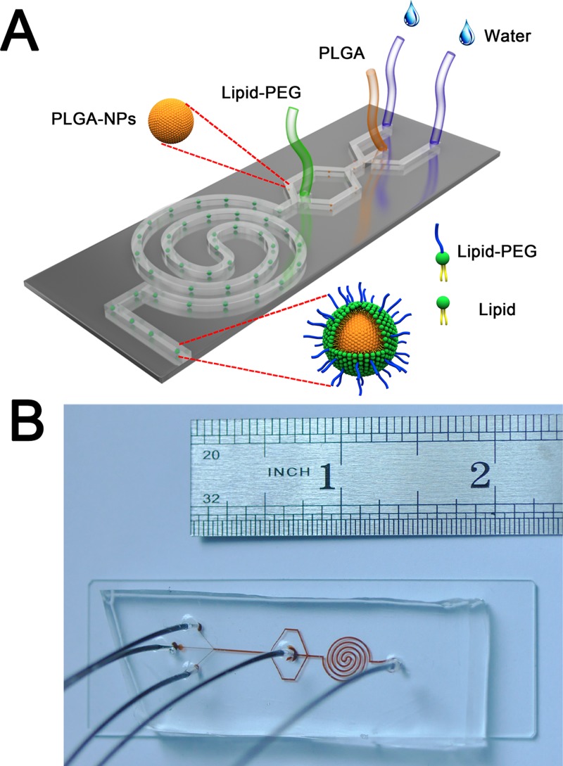
The design of the two-stage microfluidic chip is shown in Fig. 1. The width of the three inlets in the first stage is 100 μm, while the width of the main channel is 300 μm. The height of channel is 42 μm. The three inlets (100 μm wide × 42 μm deep) in the first stage are connected to a main straight channel (100 μm wide × 42 μm deep × 9 mm long), where the nano-precipitation of PLGA cores of hybrid NPs occurs. The straight channel is then divided to two branches as the two side streams for the second stage (300 μm wide × 42 μm deep), and the center inlet of the second stage is 300 μm wide × 42 μm deep. The main channel of the second stage is a 4-loop double spiral (300 μm wide × 42 μm deep), for assembling the lipid shell onto the PLGA core to form the lipid-PLGA hybrid NPs, which are collected from the outlet of the two-stage chip.31,32
FIG. 1.
(a) Schematic of the two-stage microfluidic chip for synthesizing the lipid-PLGA hybrid NPs. The PLGA core of hybrid NP is formed by nano-precipitation in the first stage of the microfluidic chip in which the PLGA solution is introduced from middle inlet and the two water sheaths are injected from two side inlets. At the second stage, the lipid solution is introduced from the center inlet, and the lipid shell is adsorbed onto the surface of PLGA core through hydrophobic interaction between the aliphatic chain of lipid and PLGA, to form the lipid-PLGA core-shell NP. (b) Photograph of the microfluidic chip.
The microfluidic device was fabricated following standard soft lithography protocol with SU8–2050 on a 4-in. silicon substrate to get a mold with microchannel height of 42 μm.33–36 The PDMS base was mixed with curing agent (Sylgard 184, Dow Corning Inc.) at the mass ratio of 10:1 and degassed before being poured over the mold. The mold with mixed PDMS was baked at 100 °C for 15 min on a heating plate. The cured PDMS was cut by a lancet and removed from the mold. Four inlets and one outlet were punched through the PDMS with a flat tip needle. The plastic tube was inserted through the ports and glued by the liquid PDMS on the top of device. The assembled device was placed into an oven and incubated at 80 °C for 45 min to cure the second layer of PDMS, followed by cutting the PDMS slab off. The PDMS slab was then bonded with a glass substrate (25 mm × 75 mm) after oxygen plasma treatment. The assembled device was finally placed into an oven at 70 °C for 20 min before use.
For the preparation of PLGA-core lipid-shell NPs (termed as PL), lipid solution (total concentration: 2.94 mg/ml) composed of DPPC (2.28 mg/ml), DSPE-PEG (0.42 mg/ml) and cholesterol (0.24 mg/ml) was used to form the lipid shell, while 1% PLGA solution (10 mg PLGA dissolved in 0.3 ml tetrafluoroethylene (TFE) and 0.7 ml dimethylformamide (DMF)) was used to form the polymeric core. Two different total flow rates were involved in the experiments. For the low flow rate synthesis, the total flow rate was 41 ml/h and the final NPs were termed as PL-41. We introduced the PLGA solution (0.5 ml/h) through the middle inlet and two water sheaths (20 ml/h each) through the two side inlets of the first stage, while at the same time injecting the lipid solution (0.5 ml/h) via the centered inlet of the second stage. For high flow rate synthesis, the total flow rate is 246 ml/h and the final NPs were termed as PL-246. We introduced the PLGA solution (3 ml/h) through the middle inlet and two water sheaths (120 ml/h each) through the two side inlets of the first stage, while simultaneously injecting the lipid solution (3 ml/h) via the centered inlet of the second stage. For the DiI-labeled NPs, 20 μg/ml DiI was dissolved in the 1% PLGA solution before the DiI/PLGA solution was injected into the chip, and DiI-labeled NPs were synthesized with the same protocol as aforementioned.
The size and the stability of the hybrid NPs were studied using dynamic light scattering (DLS, Zetasizer 3000HS, Malvern Instruments Ltd.). A 40 μl NP suspension was placed in a mini-DLS cuvette and measured with DLS. Three measurements were performed on each sample. We also used transmission electron microscopy (TEM, FEI Tecnai T20) to characterize the hybrid NPs. The sample for TEM imaging was prepared by dropping a drop of the NP suspension onto a carbon-coated copper grid pretreated with oxygen plasma (60 W, 10 s). The sample was negatively stained with uranyl acetate staining solution for 2 min at room temperature. The stained grid was air-dried at room temperature for 12 h and observed by TEM at the acceleration voltage of 200 kV.
To visualize the flow field in the microchannels, 200 μM Rhodamine B was dissolved in water which was introduced into the chip from the middle inlet of the first stage, and 50 μM calcein dissolved in water was introduced from the center inlet of the second stage. The microfluidic chip was mounted onto the stage of a Zeiss LSM710 confocal laser scanner microscope. Fluorescent images at different sites of the chip were obtained by a CCD camera. The mixing was detected at two different total flow rates, 41 ml/h and 246 ml/h.
Numerical simulation was performed to investigate the mixing process in the two-stage microfluidic chip at both low (41 ml/h) and high (246 ml/h) flow rates. The flow field and species transportation were numerically simulated by commercial CFD software Fluent 6.4 (Ansys Inc.).37,38 Hexahedral grids inside the two-stage chip were generated by Gambit (Fluent 6.4, Ansys Inc.). All walls of the microfluidic channels were set as non-slip boundary conditions. Mass flow boundary condition was applied at the four inlets and outflow condition was applied at the outlet.
We used the confocal laser scanner microscope to visualize the aggregation of NPs in complete medium containing serum. The DiI-labeled NPs (PL-41 and PL-246) were diluted with Dulbecco's modified Eagle's medium (DMEM) with 10% fetal bovine serum (FBS) (1:10) and added to a cell culture dish. The final concentration of DiI in the medium was 25 ng/ml. After incubation for 3 h, we visualized the fluorescent of DiI with a Zeiss LSM710 confocal laser scanner microscope.
The DiI-labeled NPs (PL-41 and PL-246) were also used to study the cellular uptake of hybrid NPs of different sizes. A375 cells (human melanoma cell line) were incubated in DMEM supplemented with 10% (FBS) and 1% penicillin/streptomycin in a 5% CO2, 37 °C incubator (Thermo Scientific). After co-incubation of DiI-labeled NPs (the final concentration of DiI in the medium was 25 ng/ml) and A375 cells for 6 h, the cells were visualized with the Zeiss LSM710 confocal laser scanner microscope. The fluorescence of the cells was quantified with Image J (NIH, version1.46r).
III. RESULTS AND DISCUSSION
A. Preparation and characterization of the NPs
The NPs are synthesized in a one-step manner in the two-stage microfluidic chip. In the first stage of the chip, the PLGA NPs are generated via a nano-precipitation process. The PLGA can be well dissolved in DMF/TFE, while is poorly dissolved in water. When the PLGA solution (the middle inlet) is introduced into the chip and mixed by a large amount of sheath water (flow rate ratio of PLGA:water is 1:80), the PLGA molecule is precipitated and the NP is formed. The precipitation rate is important for the size-controlled synthesis, which can be influenced by the mixing between the middle inlet and water sheath. Since the diameter of the hybrid NPs is determined by the PLGA other than the lipid shell, the mixing in the first stage is more important to the size-controlled synthesis. In the second stage, the lipid dissolved in ethanol is introduced into the chip and the aliphatic chain is self-assembled to surface of the PLGA core. We should note that the spiral channel at the second stage is designed for enhanced mixing to efficiently assemble lipid shells onto the PLGA cores. Our previous investigation shows that the curvature of spiral channel could induce secondary Dean flow perpendicular to the flow direction, resulting in the generation of two counter-rotating vortices to efficiently increase the local mixing.29,35 For the DiI-loading NPs, the DiI is encapsulated in the PLGA core as a result of the hydrophobic interaction between PLGA and DiI.
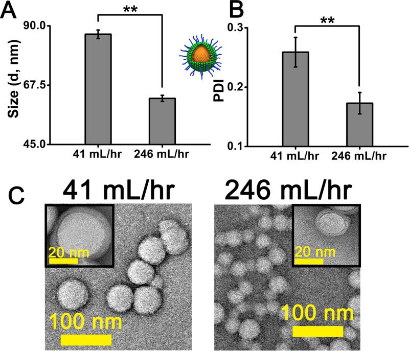
We synthesize NPs at two different total flow rates, 246 ml/h and 41 ml/h. The obtained NPs are termed as PL-246 and PL-41 for the flow rate of 246 ml/h and 41 m/h, respectively. The low flow rate results in the generation of large PL-41 NPs of 86.81 ± 1.59 nm in diameter with a polydispersity index (PDI) of 0.259 ± 0.025 (Fig. 2). In comparison, PL-246 NPs synthesized at the high flow rate are 62.5 ± 1.18 nm in diameter with a smaller PDI of 0.173 ± 0.018, indicating a narrower size distribution than that of PL-41 (Fig. 2). We also fabricate the core-shell NPs at several intermediate flow rates between 41 and 246 ml/h. The sizes of generated NPs range from 60 to 90 nm in diameter, but no gradual decrease in size with increased flow rate is observed. This might be due to the sudden change from diffusive mixing at a low flow rate to convective mixing at a high flow, which is very complex and not conclusive yet. To investigate the flow phenomena inside the two-stage microfluidic chip, both the experimental and numerical studies are performed in Sec. III B.
FIG. 2.
(a) Size distribution of lipid-PLGA hybrid NPs synthesized at different flow rates measured by dynamic light scattering (DLS). (b) Polydispersity index (PDI) of lipid-PLGA hybrid NPs by DLS. (c) TEM images of lipid-PLGA hybrid NPs synthesized at low (41 ml/h) and high (246 ml/h) flow rates. The inserted images clearly show the core-shell structure of hybrid NPs.
B. Mixing inside the two-stage microfluidic chip
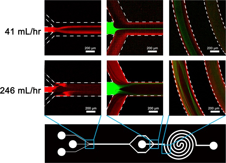
Nano-precipitation is based on the interfacial deposition of polymeric NPs when water-miscible solvents containing dissolved polymer mix with water.29 To generate uniform and size-controlled NPs by nano-precipitation, rapid and sufficient mixing is generally required. The mixing inside the two-stage microfluidic chip at both low (41 ml/h) and high (246 ml/h) flow rates was observed by confocal microscope. At a low flow rate, the Rhodamine B solution introduced from the middle inlet of the first stage (0.5 ml/h) was branched into two streams (indicated by two fluorescent red bands) by the sided water sheaths at 20 ml/h each (Fig. 3). As to the second stage, the calcein solution injected from the center inlet was hydrodynamically focused into a narrow band (indicated by fluorescent green line) by two diluted Rhodamine B streams (Fig. 3). The mixing of calcein and Rhodamine B solutions was occurred inside the 4-loop double spiral. If we increased the total flow rate to 246 ml/h while kept the flow rate ratio constant, a convective and enhanced mixing of Rhodamine B solution (at 3 ml/h) and two water sheaths (at 120 ml/h each) was observed at the first stage (Fig. 3). Meanwhile, the mixing of calcein (at 3 ml/h) and Rhodamine B solutions was also significantly enhanced at the second stage (Fig. 3). The violent mixing results in a more efficient and rapid interfacial deposition of small-sized and mono-disperse lipid-PLGA NPs at the high flow rate.
FIG. 3.
Confocal images of fluidic mixing at different regions of two-stage microfluidic chip under low (41 ml/h) and high (246 ml/h) flow rates. Rhodamine B solution (fluorescent red) is introduced into the first stage from the middle inlet, and calcein solution (fluorescent green) is injected into the second stage from the center inlet. The flow rate ratio of two side water sheaths to Rhodamine B solution is 80 at the first stage. The flow rate of Rhodamine B (or calcein) is 0.5 ml/h when the total flow rate is 41 ml/h, and 3 ml/h when the total flow rate is 246 ml/h.
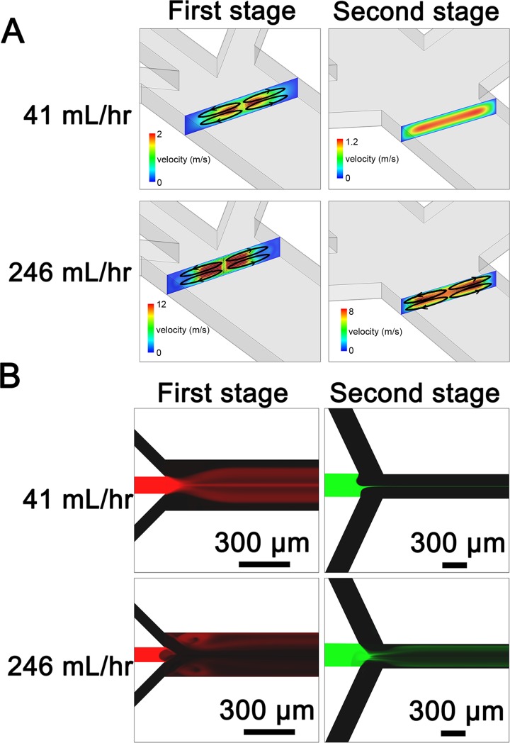
To investigate the flow fields inside the two-stage microfluidic chip, we performed a three-dimensional (3D) numerical simulation using Fluent. For the first stage at a low flow rate, four vortices perpendicular to the flow direction were generated at the junction between three inlets and main channel due to a high flow rate ratio of 80 between two side inlet steams (20 ml/h each) to the middle inlet stream (0.5 ml/h) (Fig. 4(a), indicated by four black ellipses). These four vortices might be responsible for the branched streams in Fig. 3. For the second stage at a low total flow rate of 41 ml/h, no vortices were observed, so that the center stream (0.5 ml/h) could be hydrodynamically focused (Fig. 4(a)). As to the first stage at a high flow rate (3 ml/h for the middle inlet and 120 ml/h for each side inlet), four vortices perpendicular to the flow direction at the intersection of the inlets became stronger, thus leading to a chaotic mixing (Fig. 4(a)). These vortices were also generated at the second stage due to the increased flow rate, resulting in an efficient mixing. The mixing inside the two-stage chip at different flow rates was also simulated by Fluent (Fig. 4(b)), which was in good agreement with experimental observation (Fig. 3).
FIG. 4.
(a) Simulating prediction of the velocity field at the intersection of the inlets of the first and second stage at low (41 ml/h) and high (246 ml/h) flow rates. At a low flow rate of 41 ml/h, four counter-rotating vortices (indicated by black ellipses) perpendicular to the flow direction are generated at the first stage, while no vortices are observed at the second stage. At a high flow rate of 246 ml/h, vortices at the intersection of inlets at the first stage become stronger compared to those generated by the low flow rate. Four vortices (indicated by black ellipses) are also formed at the second stage at a total flow rate of 246 ml/h. (b) Simulating prediction of mixing inside the two-stage chip at different flow rates, which is in good agreement with experimental observation in Fig. 3.
C. The stability of NPs with different sizes
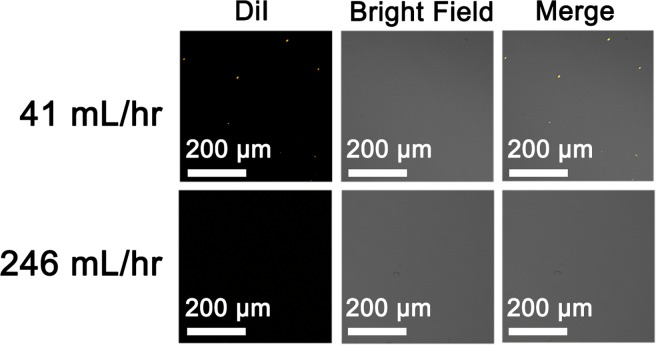
The good stability of the NPs in a serum existing environment is a prerequisite for potential biological applications. In this study, we used confocal laser scanner microscope to investigate the stability of DiI-labeled PL-41 and PL-246 NPs in complete medium containing serum, which can mimic the physiological condition. DiI is a kind of lipophilic fluorescent stain for labeling cell membranes and other hydrophobic structures, which has been widely used to label NPs for in vitro observation. Instead of labeling the lipid shell of hybrid NPs, DiI was used to label the PLGA core, so that the chance of DiI leakage from the NPs was significantly reduced. The DiI-labeled NPs were then incubated inside the complete medium (the final concentration of DiI in the medium was 25 ng/ml). Since the resolution of the confocal laser scanner microscope is ∼several hundreds of nm, we cannot detect the fluorescence signal of well-dispersed DiI-labeled NPs. However, if several NPs aggregated into a large one, the fluorescence signal of aggregated NPs became detectable. As Fig. 5 presents, there are several fluorescent dots observed by confocal microscope in the medium containing PL-41 NPs due to the particle aggregation, while no dots are detected in the medium containing PL-246 NPs, indicating that the small PL-246 NPs are not prone to aggregate. Previous study indicated that lipid-polymer hybrid NPs showed a good stability in serum existing environment since the lipid shell could act as a stealth corona to avoid aggregation, whereas the bare PLGA NPs aggregated visibly in medium containing serum.39 In our study, we also find that the small hybrid NPs are more stable than large ones, possibly due to the decreased surface free energy of small NPs which may lead to an increased stability.40
FIG. 5.
Confocal images of the aggregated lipid-PLGA NPs in complete medium containing serum. The DiI-labeled NPs (PL-41 and PL-246) are incubated with complete medium (DMEM with 10% FBS) for 3 h. The final concentration of DiI in medium is 25 ng/ml. After incubation, the NPs in medium are visualized with confocal laser scanner microscope and the aggregated NPs can be detected as fluorescent dots (orange dots).
D. Cellular uptake of DiI-labeled NPs
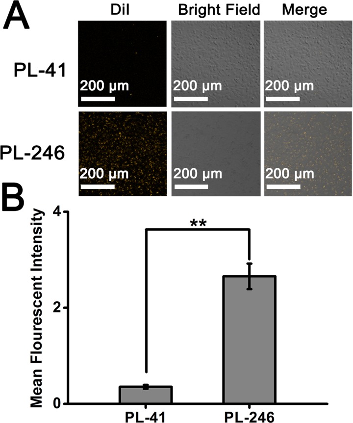
For a nano-delivery system, the cellular uptake is considered to be the first and most important indicator of biological effects.41 In this study, the cellular uptake of hybrid NPs (PL-41 and PL-246) of different diameters was investigated by co-incubation of NPs with A375 cells, and observed using a confocal laser scanner microscope. The DiI-labeled NPs were added into the complete medium to prepare the NPs-contained medium (the DiI concentration in medium was 25 ng/ml). A375 cells were cultured for 8 h to be attached to the cell culture dish. The cell culture medium was then replaced with the fresh medium containing DiI-labeled NPs. After incubating for 6 h, the cells were visualized with a confocal microscope. The cells treated with the PL-246 NPs exhibit much higher fluorescent intensity than those treated with PL-41 NPs, showing that the small PL-246 NPs could be uptaken by A375 cells more easily than large PL-41 NPs (Fig. 6).
FIG. 6.
Cellular uptake of lipid-PLGA NPs (PL-41 and PL-246) synthesized at different flow rates. The DiI is used to label the NPs (the final concentration of DiI in complete medium is 25 ng/ml). (a) Confocal images of A375 cells treated with NPs synthesized at different flow rates. (b) Quantitative results of the fluorescent intensity in (a) measured by Image J.
The cellular uptake of NPs of different sizes has been investigated intensively. NPs could be internalized via receptor-mediate endocytosis, while small NPs are more efficient in particle-cell membrane interaction than large ones.42 The chitosan NPs of around 150 nm could be internalized into non-phagocytic cells by endocytosis more rapidly than NPs of 300 nm in diameter.43 The smaller gold NPs were more prone to be uptaken by cells than large ones.44 Our study also showed that the small PLGA-core lipid-shell NPs of ∼60 nm were more efficient for cell internalization than large ones of ∼90 nm. As the optimal size of NPs is dependent on the particle material, surface charge, and so forth, our microfluidic system could provide a feasible platform for rapidly generating NPs of different biophysical properties.
IV. CONCLUSION
In this work, we synthesized size-tunable PLGA-core lipid-shell type hybrid NPs with a two-stage microfluidic platform at different flow rates. The low flow rate (41 ml/h) resulted in the generation of large NPs (average diameter of 86.8 nm with PDI of ∼0.26), whereas the high flow rate (246 ml/h) yielded small and uniform NPs (average diameter of 62.5 nm with PDI of ∼0.17). To elucidate the underlying mechanism, the mixing inside the two-stage chip was observed by confocal microscope and simulated by a 3D numerical model. Both experimental and numerical results indicated an enhanced mixing effect at the high flow rate, thus resulting in the assembly of small and mono-disperse hybrid NPs. Moreover, we demonstrated that the large lipid-PLGA NPs were more likely to be aggregated in serum and exhibited a lower cellular uptake efficacy than the small ones. This high-throughput and versatile microfluidic platform might be widely applicable for controlled synthesis of functional NPs and rapid screening of nano-drug delivery systems.
ACKNOWLEDGMENTS
This work was supported financially by MOST (2013AA032204 and 2013YQ190467), NSFC (21475028, 11422215, and 11272327), and Chinese Academy of Sciences (XDA09030305 and XDA09030308).
References
- 1. Teo B. M., Hosta-Rigau L., Lynge M. E., and Stadler B., Nanoscale 6, 6426 (2014). 10.1039/c4nr00459k [DOI] [PubMed] [Google Scholar]
- 2. Wang Y., Gao S., Ye W. H., Yoon H. S., and Yang Y. Y., Nat. Mater. 5, 791 (2006). 10.1038/nmat1737 [DOI] [PubMed] [Google Scholar]
- 3. Li S. D., Chen Y. C., Hackett M. J., and Huang L., Mol. Ther. 16, 163 (2008). 10.1038/sj.mt.6300323 [DOI] [PMC free article] [PubMed] [Google Scholar]
- 4. Feng Q., Yu M. Z., Wang J. C., Hou W. J., Gao L. Y., Ma X. F., Pei X. W., Niu Y. J., Liu X. Y., Qiu C., Pang W. H., Du L. L., and Zhang Q., Biomaterials 35, 5028 (2014). 10.1016/j.biomaterials.2014.03.012 [DOI] [PubMed] [Google Scholar]
- 5. Sengupta S., Eavarone D., Capila I., Zhao G., Watson N., Kiziltepe T., and Sasisekharan R., Nature 436, 568 (2005). 10.1038/nature03794 [DOI] [PubMed] [Google Scholar]
- 6. Acharya S. and Sahoo S. K., Adv. Drug Delivery Rev. 63, 170 (2011). 10.1016/j.addr.2010.10.008 [DOI] [PubMed] [Google Scholar]
- 7. Bala I., Hariharan S., and Kumar M. N. V. R., Crit. Rev. Ther. Drug 21, 387 (2004). 10.1615/CritRevTherDrugCarrierSyst.v21.i5.20 [DOI] [PubMed] [Google Scholar]
- 8. Kim D. H. and Martin D. C., Biomaterials 27, 3031 (2006). 10.1016/j.biomaterials.2005.12.021 [DOI] [PubMed] [Google Scholar]
- 9. Shi J. J., Xiao Z. Y., Votruba A. R., Vilos C., and Farokhzad O. C., Angew. Chem. Int. Ed. 50, 7027 (2011). 10.1002/anie.201101554 [DOI] [PMC free article] [PubMed] [Google Scholar]
- 10. Moghimi S. M. and Szebeni J., Prog. Lipid Res. 42, 463 (2003). 10.1016/S0163-7827(03)00033-X [DOI] [PubMed] [Google Scholar]
- 11. Zhang L., Feng Q., Wang J. L., Sun J. S., Shi X. H., and Jiang X. Y., Angew. Chem. Int. Ed. 54, 3952 (2015). 10.1002/anie.201500096 [DOI] [PMC free article] [PubMed] [Google Scholar]
- 12. Sun J. S., Zhang L., Wang J. L., Feng Q., Liu D. B., Yin Q. F., Xu D. Y., Wei Y. J., Ding B. Q., Shi X. H., and Jiang X. Y., Adv. Mater. 27, 1402 (2015). 10.1002/adma.201404788 [DOI] [PubMed] [Google Scholar]
- 13. Yang Y. Y., Chung T. S., and Ng N. P., Biomaterials 22, 231 (2001). 10.1016/S0142-9612(00)00178-2 [DOI] [PubMed] [Google Scholar]
- 14. Datta S. S., Abbaspourrad A., Amstad E., Fan J., Kim S. H., Romanowsky M., Shum H. C., Sun B. J., Utada A. S., Windbergs M., Zhou S. B., and Weitz D. A., Adv. Mater. 26, 2205 (2014). 10.1002/adma.201305119 [DOI] [PubMed] [Google Scholar]
- 15. Cohen-Sela E., Chorny M., Koroukhov N., Danenberg H. D., and Golomb G., J. Controlled Release 133, 90 (2009). 10.1016/j.jconrel.2008.09.073 [DOI] [PubMed] [Google Scholar]
- 16. Jain R. A., Biomaterials 21, 2475 (2000). 10.1016/S0142-9612(00)00115-0 [DOI] [PubMed] [Google Scholar]
- 17. Stadler B., Chandrawati R., Price A. D., Chong S. F., Breheney K., Postma A., Connal L. A., Zelikin A. N., and Caruso F., Angew. Chem. Int. Ed. 48, 4359 (2009). 10.1002/anie.200900386 [DOI] [PubMed] [Google Scholar]
- 18. Karnik R., Gu F., Basto P., Cannizzaro C., Dean L., Kyei-Manu W., Langer R., and Farokhzad O. C., Nano Lett. 8, 2906 (2008). 10.1021/nl801736q [DOI] [PubMed] [Google Scholar]
- 19. Okushima S., Nisisako T., Torii T., and Higuchi T., Langmuir 20, 9905 (2004). 10.1021/la0480336 [DOI] [PubMed] [Google Scholar]
- 20. Zhang L. F., Chan J. M., Gu F. X., Rhee J. W., Wang A. Z., Radovic-Moreno A. F., Alexis F., Langer R., and Farokhzad O. C., ACS Nano 2, 1696 (2008). 10.1021/nn800275r [DOI] [PMC free article] [PubMed] [Google Scholar]
- 21. Valencia P. M., Basto P. A., Zhang L. F., Rhee M., Langer R., Farokhzad O. C., and Karnik R., ACS Nano 4, 1671 (2010). 10.1021/nn901433u [DOI] [PMC free article] [PubMed] [Google Scholar]
- 22. Hong J. S., Stavis S. M., Lacerda S. H. D., Locascio L. E., Raghavan S. R., and Gaitan M., Langmuir 26, 11581 (2010). 10.1021/la100879p [DOI] [PubMed] [Google Scholar]
- 23. Menon N. V., Chuah Y. J., Cao B., Lim M., and Kang Y. J., Biomicrofluidics 8, 064118 (2014). 10.1063/1.4903762 [DOI] [PMC free article] [PubMed] [Google Scholar]
- 24. Chen S., Zhang H. J., Shi X. T., Wu H. K., and Hanagata N., Lab Chip 14, 1842 (2014). 10.1039/c4lc00015c [DOI] [PubMed] [Google Scholar]
- 25. Chen Q. L., Liu Z., and Shum H. C., Biomicrofluidics 8, 064112 (2014). 10.1063/1.4902929 [DOI] [PMC free article] [PubMed] [Google Scholar]
- 26. Xia H. M., Seah Y. P., Liu Y. C., Wang W., Toh A. G., and Wang Z. P., “ Anti-solvent precipitation of solid lipid nanoparticles using a microfluidic oscillator mixer,” Microfluid. Nanofluid. (2014). 10.1007/s10404-014-1517-5 [DOI]
- 27. Lim J. M., Bertrand N., Valencia P. M., Rhee M., Langer R., Jon S., Farokhzad O. C., and Karnik R., Nanomedicine 10, 401 (2014). 10.1016/j.nano.2013.08.003 [DOI] [PMC free article] [PubMed] [Google Scholar]
- 28. Andar A. U., Hood R. R., Vreeland W. N., Devoe D. L., and Swaan P. W., Pharm. Res. 31, 401 (2014). 10.1007/s11095-013-1171-8 [DOI] [PubMed] [Google Scholar]
- 29. Sun J. S., Xianyu Y. L., Li M. M., Liu W. W., Zhang L., Liu D. B., Liu C., Hu G. Q., and Jiang X. Y., Nanoscale 5, 5262 (2013). 10.1039/c3nr01289a [DOI] [PubMed] [Google Scholar]
- 30. Wang J. D., Chen W. W., Sun J. S., Liu C., Yin Q. F., Zhang L., Xianyu Y. L., Shi X. H., Hu G. Q., and Jiang X. Y., Lab Chip 14, 1673 (2014). 10.1039/c4lc00080c [DOI] [PubMed] [Google Scholar]
- 31. Zhu J. J. and Xuan X. C., Biomicrofluidics 5, 024111 (2011). 10.1063/1.3599883 [DOI] [Google Scholar]
- 32. DuBose J., Lu X. Y., Patel S., Qian S. Z., Joo S. W., and Xuan X. C., Biomicrofluidics 8, 014101 (2014). 10.1063/1.4862355 [DOI] [PMC free article] [PubMed] [Google Scholar]
- 33. Yuan B., Jin Y., Sun Y., Wang D., Sun J. S., Wang Z., Zhang W., and Jiang X. Y., Adv. Mater. 24, 890 (2012). 10.1002/adma.201104589 [DOI] [PubMed] [Google Scholar]
- 34. Sun J., Stowers C. C., Boczko E. M., and Li D., Lab Chip 10, 2986 (2010). 10.1039/c005029f [DOI] [PMC free article] [PubMed] [Google Scholar]
- 35. Sun J. S., Liu C., Li M. M., Wang J. D., Xianyu Y. L., Hu G. Q., and Jiang X. Y., Biomicrofluidics 7, 011802 (2013). 10.1063/1.4774311 [DOI] [PMC free article] [PubMed] [Google Scholar]
- 36. Sun J. S., Vajandar S. K., Xu D. Y., Kang Y. J., Hu G. Q., Li D. Q., and Li D. Y., Microfluid. Nanofluid. 6, 589 (2009). 10.1007/s10404-008-0331-3 [DOI] [Google Scholar]
- 37. Shen F., Li X. J., and Li P. C. H., Biomicrofluidics 8, 014109 (2014). 10.1063/1.4866358 [DOI] [PMC free article] [PubMed] [Google Scholar]
- 38. Liu C., Hu G., Jiang X., and Sun J., Lab Chip 15, 1168 (2015). 10.1039/C4LC01216J [DOI] [PubMed] [Google Scholar]
- 39. Fang R. H., Aryal S., Hu C. M. J., and Zhang L. F., Langmuir 26, 16958 (2010). 10.1021/la103576a [DOI] [PubMed] [Google Scholar]
- 40. Xiong S. Y., Qi W. H., Cheng Y. J., Huang B. Y., Wang M. P., and Li Y. J., Phys. Chem. Chem. Phys. 13, 10648 (2011). 10.1039/c0cp02102d [DOI] [PubMed] [Google Scholar]
- 41. Stadler B., Price A. D., and Zelikin A. N., Adv. Funct. Mater. 21, 14 (2011). 10.1002/adfm.201001676 [DOI] [Google Scholar]
- 42. Win K. Y. and Feng S. S., Biomaterials 26, 2713 (2005). 10.1016/j.biomaterials.2004.07.050 [DOI] [PubMed] [Google Scholar]
- 43. He C. B., Hu Y. P., Yin L. C., Tang C., and Yin C. H., Biomaterials 31, 3657 (2010). 10.1016/j.biomaterials.2010.01.065 [DOI] [PubMed] [Google Scholar]
- 44. Chithrani B. D. and Chan W. C. W., Nano Lett. 7, 1542 (2007). 10.1021/nl070363y [DOI] [PubMed] [Google Scholar]


