Abstract
The geometric and electronic structure of the active site of the non-heme iron enzyme nitrile hydratase (NHase) is studied using sulfur K-edge XAS and DFT calculations. Using thiolate (RS−)-, sulfenate (RSO−)-, and sulfinate (RSO2−)-ligated model complexes to provide benchmark spectral parameters, the results show that the S K-edge XAS is sensitive to the oxidation state of S-containing ligands and that the spectrum of the RSO− species changes upon protonation as the S–O bond is elongated (by ~0.1 Å). These signature features are used to identify the three cysteine residues coordinated to the low-spin FeIII in the active site of NHase as CysS−, CysSOH, and CysSO2− both in the NO-bound inactive form and in the photolyzed active form. These results are correlated to geometry-optimized DFT calculations. The pre-edge region of the X-ray absorption spectrum is sensitive to the Zeff of the Fe and reveals that the Fe in [FeNO]6 NHase species has a Zeff very similar to that of its photolyzed FeIII counterpart. DFT calculations reveal that this results from the strong π back-bonding into the π* antibonding orbital of NO, which shifts significant charge from the formally t26 low-spin metal to the coordinated NO.
Introduction
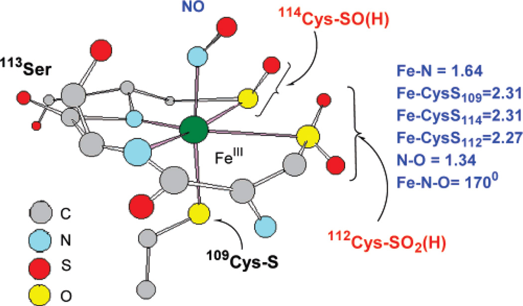
Nitrile hydratase (NHase) hydrolyzes nitriles to amides and is used in the industrial preparation of acrylamide.1–3 The active site can contain either a low-spin FeIII or a low-spin CoIII ion coordinated by three cysteines and two deprotonated amides (two amides and two cysteines occupying the equatorial plane with an axial cysteine).5–7 The Fe enzyme is isolated in a diamagnetic NO-bound form, activated by irradiation, and is proposed to be stabilized by the presence of butyric acid in the medium.4 The sixth coordination site is occupied by a NO (as isolated) or an HxO molecule (after photolysis).8,9 In a recent crystal structure of the inactive NO-bound form3a (Figure 1a), the cysteine ligands are post-translationally modified to RSO-(H) and RSO2(H) in contrast to a previously reported crystal structure showing non-oxidized CysS− coordination (Figure 1).3b However, aside from FT-IR, there are no direct spectroscopic probes of the CysS− ligand oxidation states in the active form of the enzyme.10 Although active sites having transition-metal-bound oxidized thiolate residues are rare in nature, mutational studies on these thiolate residues have shown them to be catalytically relevant.11,12
Figure 1.
Proposed active-site structure of NHase from the 1.7-Å resolution crystal structure.3a
The catalytic mechanism of this site is not well understood, and there are several proposals regarding the role of the low-spin FeIII center in activating nitriles for hydrolysis.13 The possible functional role of these modified cysteines, and the electronic structure of the as-isolated [FeNO]6 species (using the Enemark–Feltham nomenclature, where the superscript 6 refers to the total number of valence electrons on the iron and the π* orbitals of NO) and its observed photochemistry, have been a focus of several recent experimental and theoretical studies.14–18 A significant number of structurally relevant model complexes have been reported, some of which bind nitriles and some of which reversibly bind NO and show photolytic behavior.19–22 Furthermore, the study of a series of model complexes having oxidized ligands has shown that this oxidation can significantly alter the pKa of a water bound to the low-spin FeIII.23
Ligand K-edge X-ray absorption spectroscopy (XAS) is a direct probe of a ligand’s chemical nature and its bonding to a metal.24,25 The primary transition at the K-edge is 1s → 4p. In the case of sulfur, transitions to other unoccupied antibonding orbitals, including the C–S σ*, O–S σ*, and M3d–S antibonding orbitals, gain intensity due to sulfur 3p mixing. The observed intensity of these transitions is then directly proportional to the extent of this mixing.26 This ligand K-edge XAS method has been used to investigate bonding in several models having different types of chlorine- and sulfur-based ligands and in the active sites of NiSOD and nickel dithiolenes, blue copper, CuA, and iron–sulfur proteins.27–32 In those studies, where the focus was on the metal–sulfur bonding and its perturbation by the protein environment, it was found that the S K-edge is very sensitive to the Zeff of a ligand, the chemical environment of the ligand, and the Zeff of the metal to which it is bound.33
In this study we apply XAS and density functional theory (DFT) to a series of crystallographically characterized model complexes to identify signature spectroscopic features associated with thiolate-based ligands having different oxidation and protonation states. We then use these features to identify the ligands present in the active site of the protein NHase in its NO-bound inactive and photolyzed active forms. We further investigate the electronic structure of [FeNO]6 NHase using DFT calculations in conjunction with the spectroscopic results.
Experimental Details
Sample Preparation
All four model complexes, FeIII(ADIT)2 (1), FeIII(ADIT)(ADIT-O) (2), [CoIII((η2-SO)(SO2)N3(Pr,Pr))] (3), and FeIII-(ADIT)(ADIT-O-ZnCl3) (4), were synthesized as reported in the literature.19,34 For XAS experiments, the samples were ground into a fine powder, dispersed as thinly as possible on sulfur-free Mylar tape in a dry, anaerobic glovebox (N2) atmosphere, and mounted across the window of an aluminum plate. This procedure has been verified to minimize self-absorption effects. A 6.35-µm polypropylene film window protected the solid samples from exposure to air during transfer from the glovebox to the experimental sample chamber.
The NO-bound NHase protein was expressed and purified as described in ref 35. The protein solutions (in 100 mM phosphate buffer, pH 7.5) were pre-equilibrated in a water-saturated He atmosphere for ~1 h to minimize bubble formation in the sample cell. The solution was loaded via a syringe into a Pt-plated Al block sample holder, sealed in front using a 6.3-µm polypropylene window. To ensure photolysis, the protein sample was illuminated by a 400-W tungsten lamp for 30 min before the XAS data measurements.
Data Collection and Reduction
XAS data were measured at the Stanford Synchrotron Radiation Laboratory using the 54-pole wiggler beam line 6-2. Details of the experimental configuration for low-energy studies have been described in an earlier publication.33 The data reduction and error analysis follow the same method discussed previously.36
Fitting Procedure
Pre-edge features were fit by pseudo-Voigt line shapes (sums of Lorentzian and Gaussian functions). This line shape is appropriate as the experimental features are expected to be a convolution of a Lorentzian transition envelope and a Gaussian line shape imposed by the spectrometer optics.37,38 A fixed 1:1 ratio of Lorentzian to Gaussian contribution successfully reproduced the pre-edge features. The rising edge was also fit with pseudo-Voigt line shapes. Good fits reproduce the data and its second derivative using a minimum number of peaks. The intensity of a pre-edge feature (peak area) is the sum of the intensity of all the pseudo-Voigt peaks which successfully fit the feature in a given fit. The reported intensity values for the proteins are averages of all good pre-edge fits.
Computational Details
All calculations were performed on dual-CPU Pentium Xeon 2.8 GHz work stations using the Amsterdam Density Functional (ADF) program, versions 2004.01, developed by Baerends et al.39,40 A triple-ζ Slater-type orbital basis set (ADF basis set TZP) with a single polarization function at the local density approximation of Vosko, Wilk, and Nusair,41 with nonlocal gradient corrections of Becke42 and Perdew,43 was employed. The molecular orbitals were plotted using Molden version 5.1, and the Mulliken44 population analyses were performed using the AOMix45 program. The calculations of the protein active site were performed using the BP86 functional as well as the hybrid B3LYP46 functional with the Gaussian 03 package.47 The solvation calculations (single points and optimizations) were performed using the PCM48 method and epsilon of 4.0. The optimizations were performed with a mixed basis set with 6-311g* on Fe, S, N, and O and 6-31g* on C and H. The single-point calculations were performed with a 6-311+g** basis set on all atoms.
Results and Analysis
A. S K-Edge XAS of Model Complexes and Free Ligands
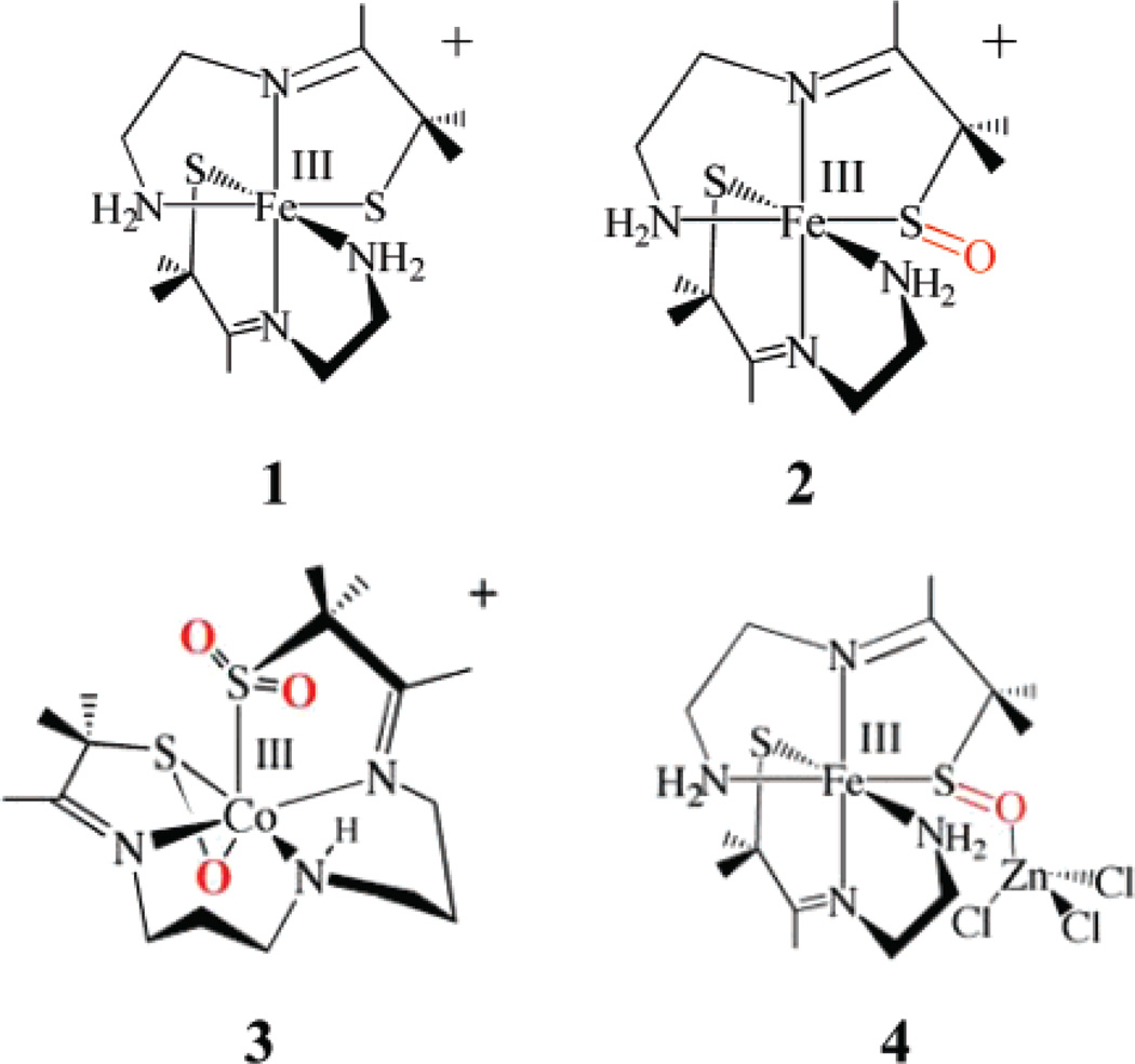
The X-ray absorption spectra of the structurally characterized model complexes [FeIII(ADIT)2]+ (1), [FeIII(ADIT)(ADIT-O)]+ (2), [CoIII(η2-SO)(SO2)N3(Pr,Pr)]+ (3), and [FeIII(ADIT)(ADITO-ZnCl3)]+ (4) (Figure 2) were used as references for ligand oxidation state determination for the NHase enzyme (Figure 1).49 Complex 1 contains a low-spin FeIII atom coordinated by two thiolates, one of which is oxidized in the low-spin complex (2). Complex 4 has a ZnCl3 moiety coordinated to the S–O moiety in 2, while 3 has a low-spin CoIII atom ligated by an η2-coordinated S–O− moiety and an RSO2 moiety coordinated through sulfur, as in the proposed active site of NHase (Figure 1).3
Figure 2.
Schematic structures of the model complexes of NHase studied.
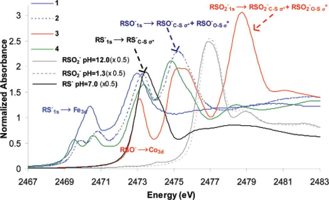
The S K-edge XAS of free cysteine at pH 7.0 (black line in Figure 3) has an intense RS−1s → RS−C–Sσ* transition at 2473.0 eV. The spectra of aqueous solutions of sulfinic acid at pH 12.0 (Figure 3, solid gray, deprotonated) and pH 1.3 (Figure 3, dashed gray, protonated) are almost identical, and the RSO2−1s → RSO2−C–Sσ* and RSO2−1s → RSO2−O–Sσ* transitions show up as a strong absorption feature at 2477.0 eV. The shift of this feature from 2473 eV in cysteine to 2477 eV in sulfinic acid reflects the stabilization of the S1s orbital due to the higher oxidation state of sulfur in the latter.33,50 The S K-edge XAS of complex 1 (Figure 3, solid blue) shows two pre-edge transitions around 2470 eV (2469.8 and 2470.5 eV) and a transition at 2473.1 eV, corresponding to RS−1s → Fe3d and RS−1s → RS−C–Sσ* transitions, respectively. The spectrum of complex 2 (Figure 3, dashed blue) also shows the two pre-edge transitions from the thiolate (now well separated) at 2469.8 and 2470.9 eV and an RS−1s → RS−C–Sσ* transition at 2473.3 eV, as well as a new third broad transition with a maximum at 2475.3 eV, which is now assigned to an envelope of the RSO−1s → RSO−C–Sσ* and RSO−1s → RSO−O–Sσ* transitions. These transitions are shifted higher in energy relative to the RS−1s → RS−C–Sσ* transitions due to the deeper energy of the 1s orbital of the oxidized sulfur in RSO−. Note that the RSO−1s → Fe3d pre-edge transition should also have intensity due to covalent bonding of the RSO− ligand to the metal d-orbitals through the sulfur. However, this would largely overlap the RS−1s → RS−C–Sσ* transition at 2473.1 eV in 2. This transition is, in fact, clearly observed at 2473.2 eV for 3 (Figure 3, red), a complex in which there is no RS− ligand and hence no RS−1s → RS−C–Sσ* transition. As for 2, complex 3 also exhibits RSO−1s → RSO−C–Sσ* and RSO−1s → RSO−O–Sσ* transitions at ~2475 eV (maxima at 2474.9 and 2475.9 eV). There is an additional higher-energy feature in the spectrum of 3 at 2478.8 eV, which is assigned to the RSO2−1s → RSO2−C–Sσ* and RSO2−1s → RSO2−O–Sσ* transitions. Note that this transition envelope is shifted up in energy by almost 2 eV for complex 3 (2478.8 eV, Figure 3, red) relative to free sulfinic acid (2477.0 eV, Figure 3, solid gray). This shift has contributions from both the increase in Zeff of sulfur in RSO2− due to its covalent bonding to the CoIII ion, which shifts the sulfur 1s orbital to deeper energy, and from the shorter S–O bonds in 3 (1.45 Å) compared to the those in the free ligand (1.51 Å), which shifts the σ* orbital to higher energy (Table 1). The XAS of complex 4 (Figure 3, green) is very similar to that of 2 (Figure 3, dashed blue) and has the same assignment of features, i.e., RS−1s → Fe3d and RS−1s → RS−C–Sσ* transitions around 2470 and 2473 eV, respectively, and RSO−1s → RSO−C–Sσ* and RSO−1s → RSO−O–Sσ* transitions at 2474.9 and 2475.9 eV, respectively.
Figure 3.
S K-edge XAS of free cysteine at pH 7 (black), OHCH2SO2− (gray) and OHCH2SO2H (dashed gray), and model complexes 1 (blue), 2 (dashed blue), 3 (red), and 4 (green).
Table 1.
DFT-Optimized Geometric Parametersa
| RS− | RSO(H) | RSO2(H) | ||||||
|---|---|---|---|---|---|---|---|---|
| M–S | C–S | M–S | C–S | S–O | M–S | C–S | S–O | |
| FeIII(ADIT)2 (1) | 2.21 (2.20) | 1.84 (1.82) | ||||||
| FeIII(ADIT)(ADIT-O) (2) | 2.19 (2.17) | 1.85 (1.84) | 2.31 (2.25) | 1.87 (1.87) | 1.55 (1.55) | |||
| CoIII((η2-SO)(SO2)N3 (Pr,Pr)) (3) | 2.18 (2.13) | 1.85 (1.83) | 1.57 (1.55) | 2.18 (2.12) | 1.87 (1.86) | 1.47 (1.46) | ||
| FeIII(ADIT)(ADIT-O-ZnCl3) (4) | 2.20 (2.16) | 1.84 (1.84) | 2.29 (2.25) | 1.86 (1.87) | 1.56 (1.57) | |||
| CH3SO− | 1.86 | 1.60 | ||||||
| CH3SOH | 1.80 | 1.72 | ||||||
| CH3SO−- -C(NH2)3+ | 1.82 | 1.64 | ||||||
| CH3SO2− | 1.90 | 1.53 | ||||||
| CH3SO2H | 1.81 | 1.49, 1.69 | ||||||
Crystal structure parameters are given within parentheses.19
It is also important to note that the broad, higher-energy transition at ~2475 eV in 2, associated with the RSO−1s → RSO−C–Sσ* and RSO−1s → RSO−O–Sσ*, is partly split in 3 and is clearly split into two features, at 2474.9 and 2475.9 eV, in 4. Note that complexes 3 and 4 both have the oxygen atom of the RSO− coordinated to a metal (CoIII in 3 and ZnII in 4), and this interaction appears to energy-split the broad feature at ~2475 eV. DFT calculations were used to evaluate the effects of metal coordination to the S, protonation/metal coordination to the O of RSO−, and protonation of RSO2−.
B. DFT Calculations of the Model Complexes and Ligands
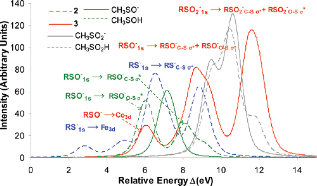
Geometry-optimized DFT calculations were performed for complexes 2 and 3 and for the free ligands CH3SO−, CH3SOH, CH3SO2−, and CH3SO2H. The optimized bond lengths are in overall good agreement with published crystal structures (Table 1). The optimized structures are used to obtain ground-state S3p orbital distributions in the unoccupied virtual orbitals for these complexes and free ligands. These calculations were used to estimate the relative energies (zero defined as 2390 eV) and intensities of their S K-edge XAS (Figure 4, predicted S K-edge).51 Though the absolute transition energies were under-estimated (due to lack of relativistic corrections), the relative energies of the pre-edge and the rising edge features are in good agreement with the experimental spectra in Figure 3.
Figure 4.
DFT-calculated ground-state S3p mixing in 2 (dashed blue), 3 (red), CH3SO2− (gray), CH3SO2H (dashed gray), CH3SO− (green), and CH3-SOH (dashed green). Zero defined at 2390 eV.
The intensity distribution for 2 (Figure 4, dashed blue) shows two features corresponding to RS−1s → Fe3d and RS−1s → RS−C–Sσ* transitions at 4.0 eV (first transition split due to ligand field effects on the 3d orbitals) and 7.0 eV, respectively. It also shows a third feature at 9.0 eV which corresponds to contributions of the RSO−1s → RSO−C–Sσ* and RSO−1s → RSO−O–Sσ* transitions. Calculations for complex 3 give the RSO−1s → Co3d transition at 6.3 eV and the RSO−1s → RSO−C–Sσ* and RSO−1s → RSO−O–Sσ* transitions at 9.0 eV (Figure 4, red). Note that the σ* transitions are separated in energy by 1 eV and that the calculations reproduce the experimentally observed energy splitting of this feature. There is an additional higher-energy feature for 3 (Figure 4, red), corresponding to the overlapping contributions from RSO2−1s → RSO2−C–Sσ* and RSO2−1s → RSO2−O–Sσ* transitions. Calculations on both free CH3SO2− and CH3SO2H show this feature at 9–11 eV (Figure 4, solid gray and dashed gray, respectively). These calculations reproduce the 2-eV increase in energy of this feature observed in the data for 3 relative to that of the free ligand and show no significant effect of protonation of the oxygen of the RSO2− group on the S3p distribution, consistent with experiment (Figure 3, solid gray and dashed gray). A calculation performed on the CH3SO2− fragment, having the geometry of complex 3 (i.e., with shorter S–O bond lengths) but not coordinated to a metal ion, shows no significant shift of the RSO2−1s → RSO2−C–Sσ* and RSO2−1s → RSO2−O–Sσ* transition energies, indicating that the experimentally observed 2-eV shift of this feature between the free ligand and complex 3 (Figure 3, red and gray lines) is a result of CoIII coordination to the sulfur of RSO2−. This shifts charge density from S to CoIII, stabilizing the S 1s orbital energy in complex 3 relative to that of the free ligand.
A DFT calculation on CH3SO− shows one feature at 7.0 eV that corresponds to an envelope of the RSO−1s → RSO−C–Sσ* and RSO−1s → RSO−O–Sσ* transitions (Figure 4, green).52 In contrast to calculations on RSO2(H), the DFT calculation on the free CH3SOH ligand shows dramatic differences in the S3p energy/intensity distribution relative to that of the CH3SO− ligand. The RSO−1s → RSO−C–Sσ* and RSO−1s → RSO−O–Sσ* transitions, which combine into one peak at 7.0 eV in the deprotonated ligand (Figure 4, solid green), are now split into two peaks (Figure 4, dashed green) at 6.0 eV (the RSO−1s → RSO−O–Sσ* transition) and 8.0 eV (the RSO−1s → RSO−C–Sσ* transition) upon protonation. Geometry-optimized DFT calculations on these free ligands (Table 1) show that the C–S bond shortens by 0.06 Å and the S–O bond elongates by 0.1 Å on protonation of CH3SO−. This shifts the C–S σ* orbital higher and the O–S σ* orbital lower in energy, resulting in the observed energy splitting of these features. A similar elongation of the S–O and shortening of the C–S bonds is observed in complexes 4 and 3 (O–S 1.56 Å, C–S 1.86 Å and O–S 1.57 Å, C–S 1.87 Å, respectively) relative to 2 (O–S 1.55 Å, C–S 1.85 Å).53 Thus, the experimentally observed energy splitting of the 2474–2476 eV features of complexes 3 and 4 is due to the weakening of the S–O and strengthening of the C–S bonds as a result of the metal coordination to the RSO− oxygen atom. The larger energy splitting for complex 4 is probably due to its stronger coordination to ZnII. As shown in Figure 4, full protonation produces the largest effect. It should be noted that for RSO2(H) the changes in bond lengths with protonation are smaller (1.53 Å vs 1.49 and 1.69 Å) and the split of the feature at 9–11 eV does not change significantly.
In summary, from the model studies it is found that the S1s → C–S σ* and S–O σ* transitions are very sensitive to the Zeff of the sulfur. RS− has RS−1s → Fe3d and RS−1s → RS−C–Sσ* transitions at ~2470 and ~2473 eV, respectively, RSO− has RSO−1s → RSO−C–Sσ* and RSO−1s → RSO−O–Sσ* transitions at 2475 eV which split by 2 eV on protonation, and RSO2− has the RSO2−1s → RSO2−C–Sσ* and RSO2−1s → RSO2−O–Sσ* transitions at 2477–2479 eV (depending on metal ion coordination) which are not significantly affected by protonation.
C. S K-Edge XAS of Nitrile Hydratase
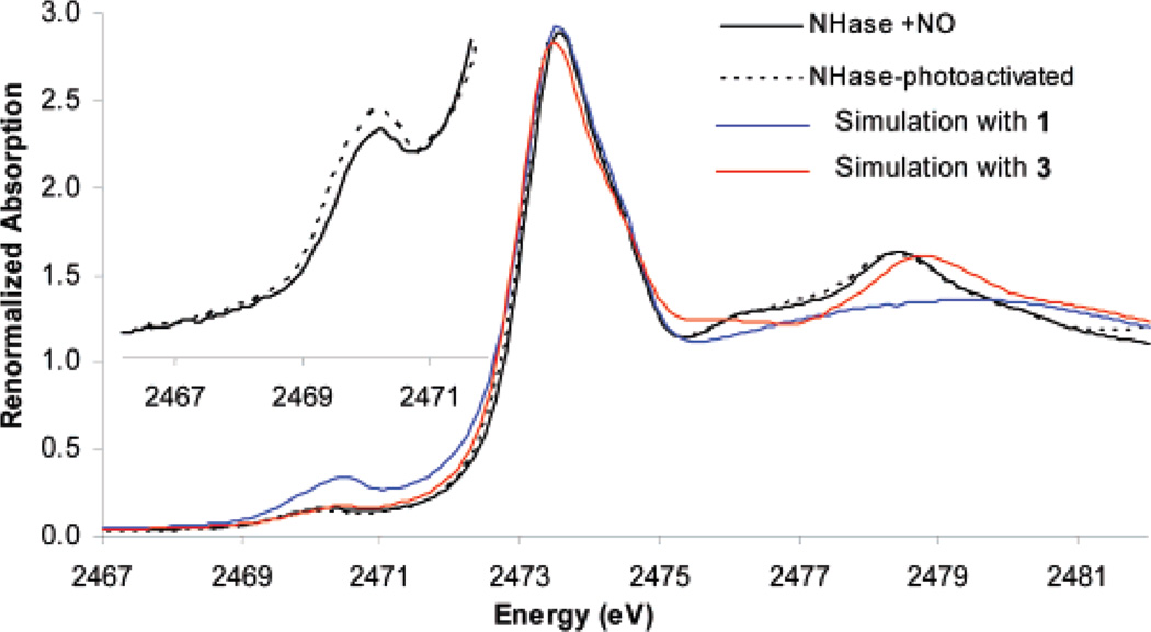
The S K-edge XAS of the inactive NO-bound form of NHase shows four distinct features (Figure 5, black). The lowest-energy feature, at 2470.1 eV (inset), is assigned as the RS−1s → Fe3d transition. The broad envelope at 2472–2474 eV can be assigned as a composite of RS−1s → RS−C–Sσ* transitions of the ligated cysteine, two free cysteines and nine methionines. The other higher-energy features, at 2476.1 and 2478.5 eV, are relatively weak; however, a simulated spectrum generated by the normalized addition of the spectra of aqueous methionine and cysteine at pH 7.5 and 1, representing thiolate coordination but no oxidized sulfur (Figure 5, blue), shows no higher-energy features. Alternatively, simulation including the oxidized ligands (Figure 5, red, complex 3) shows two higher-energy features at 2475–2476 and 2475.5–2479.5 eV, similar to those for NHase-NO at 2476.1 and 2478.5 eV, indicating that they are associated with the oxidized sulfur ligands present in the NO-bound form of the protein. The feature at 2478.5 eV for the enzyme can be assigned to RSO2−. Note that this is at a higher energy than for the RSO2−1s → RSO2−C–Sσ* and RSO2−1s → RSO2−O–Sσ* transitions observed for the free RSO2− ligand (at 2476–2478 eV, Figure 3, gray) but lower than those for the CoIII complex 3 (at 2478.8 eV, Figure 3, red), indicating coordination of the CysSO2− ligand at the protein active site but with a weaker bond relative to complex 3.
Figure 5.
S K-edge XAS of NHase-NO (black), NHase-photoactivated (dashed black), simulation with 1 only (blue), and simulation with 3 (red). Inset: Expanded pre-edge region of NHase-NO and NHase-photoactivated.
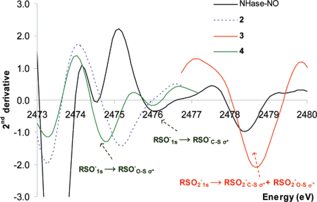
The feature at 2476.1 eV could originate from RSO−, although this feature is shifted to higher energy by ~1 eV than is observed for RSO− in complexes 2 and 3. In sections A and B (vide supra), it is shown that the energy of the RSO− feature is sensitive to the chemical environment of the oxygen. Inspection of the second derivatives of the absorption data (where minima in second derivative represent maxima in the absorption spectrum) (Figure 6) reveals that the NHase-NO enzyme data has a minimum at 2476.1 eV (Figure 6, black), while the RSO−-ligated complex (2) has a broad minimum at 2475.2 eV (Figure 6, dashed blue). In 4 (Figure 6, green), where Zn2+ is strongly bound to the O of RSO−, the RSO−1s → RSO−S–Oσ* feature has shifted down to 2474.8 eV, reflecting a weaker S–O bond in 4, while the RSO−1s → RSO−C–Sσ* negative feature remains at 2476.1 eV. As found in section B, protonation of RSO− will shift the S–O σ* transition to 2 eV lower in energy than the C–S σ* transition, due to the elongation of the S–O bond. Hence, the absence of a single minimum in the second derivative, corresponding to a peak in absorption between 2474 and 2475 eV in the NHase data, argues against the presence of an RSO− residue and indicates that the cysteine sulfenic acid residue in the NHase active site is protonated. While the RSO(H)1s → RSO(H)C–Sσ* transition is observed in the data for NHase (Figure 6, black) at 2476.1 eV, about 1.0 eV higher than the single peak observed for 2 (which can be used as an estimate of the energy position of a pure RSO− feature), the RSO(H)1s → RSO(H)S–Oσ* transition of Nhase, which is estimated to be 2 eV lower in energy relative to the RSO(H)1s → RSO(H)C–Sσ* transition, could be merged into the RS−1s → RS−C–Sσ* transition envelope at 2472–2474 eV.54
Figure 6.
Second derivative of XAS data of 2 (dashed blue), 3 (red), 4 (green), NHase-NO (black), and NHase-photoactivated (dashed black).
S K-edge XAS data for the photoactivated protein (Figure 5, dashed black) show no significant change relative to the data for the inactive NO-bound NHase. This indicates that the oxidation states of the metal and the sulfur ligands and the protonation state of RSO− are virtually identical in the NO-bound inactive and the photolyzed active enzyme. However, there is a markedly increased pre-edge intensity upon photolysis (Figure 5, inset), which is analyzed in section E.
D. DFT Calculations on the Active Site of NHase
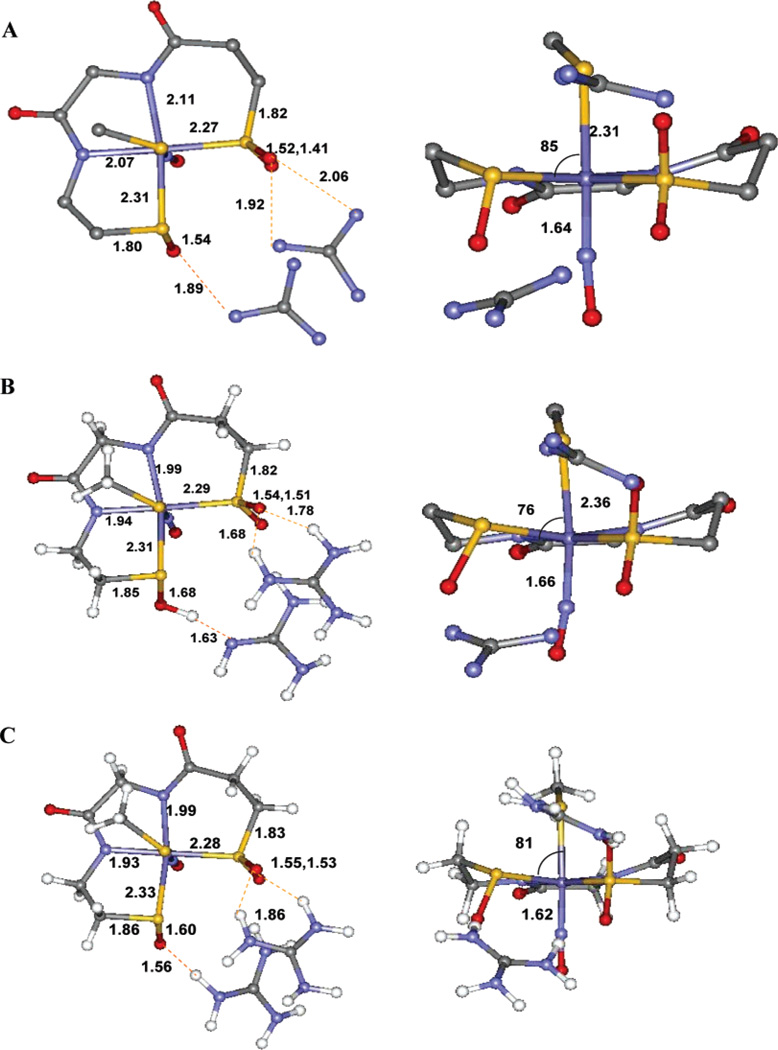
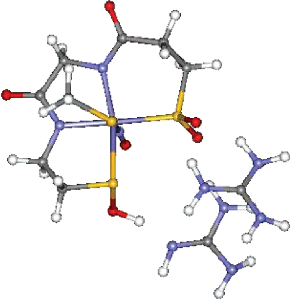
While the S K-edge XAS data for the protein active site and model complexes enabled us to assign the chemical nature of two of the three cysteinyl ligands (CysS− and CysSOH), it could not help to discern the protonation state of the CysSO2− ligand. Geometry-optimized DFT calculations were performed on the crystallographically characterized NO-bound inactive form to evaluate this issue (Figure 7A). The active site was modeled using two oxidized cysteines coordinated to the Fe in the equatorial plane (Cys 114, Cys 112) and a methyl thiolate modeling the axial cysteine (Cys 109). There are two hydrogen bonds from nearby arginine residues (Arg 141 and Arg 56) which are modeled by two C(NH2)3+ fragments.55 The optimized structures show that the CysSO2− remains in its ionized form. This is reasonable as the pKa of RSO2− is 6–7 and that of arginine is 12–14; hence, they are expected to be ionized under the experimental conditions. Also, in a vacuum the charged species should neutralize while they may not do so in a PCM calculation. On the contrary, the proton from the C(NH2)3+ fragment, H-bonding to CysSO−, shifts to the CysSO− oxygen, producing a neutral CysSOH species (Figure 7B). This computational model agrees well with the geometric structure obtained from the XAS data as the optimized geometry displays a long (1.68 Å) S–O bond upon protonation, which will split the RSO−1s → RSO−C–Sσ* and RSO−1s → RSO−O–Sσ*, as observed experimentally. However, it must be noted that the pKa of the RSO− residue is 10–11 and that for arginine is 12–14.56 As indicated above, the protonation state of the arginine-CysSO unit will depend on the dielectric constant of the medium. Geometry optimizations were also performed using a PCM solvation model with an epsilon of 4.0. The results of this optimization show that the CysSO− and the C(NH2)3+ residues remain charge-separated after optimization (Figure 7C), in contrast to the vacuum-based calculations and the experimental results from XAS. However, the energy difference between the CysSOH–C(NH2)2(NH) and the CysSO−–C(NH2)3+ forms is only 4 kcal/mol and depends on modeling of the active site and the functional used (4 kcal/mol for B3LYP and 7 kcal/mol for BP86).57 This energy difference corresponds to a pKa difference of 3 units. An electrostatic calculation (not included in the DFT modeling) of the pKa’s for the buried arginines in Nhase shows that these vary over the range 16.6 (the surface residues have ~12) to 8.5, with one of the two (Arg 167) H-bonded to the SO− ligand having a pKa of 9.3.58
Figure 7.
(A) 1.6-Å resolution crystal structure of the NHase-NO complex active site. (B) Optimized geometry, gas phase. (C) Optimized geometry, PCM, ε = 4.0.
E. Pre-edge Analysis
Due to covalent interaction with the axial CysS−, the unoccupied 3d orbitals of the NO-bound NHase active site will have S3p mixing, and hence will exhibit RS−1s → Fe3d transition intensity, which is proportional to the coefficient of S3p mixing in these orbitals. The S K-edge XAS of the NO-bound inactive form has a distinct pre-edge feature with a maximum at 2470.0 eV (Figure 6, inset, black). The renormalized intensity of this pre-edge feature is 0.69 unit, which correspond to 20% S3p character mixed into the antibonding 3d orbital (Table 2). The NHase-photoactivated sample has two pre-edge features, one at 2469.6 eV and a second at 2470.2 eV, with 0.31 and 0.51 unit of intensity, respectively (Figure 6, inset, dashed black). This indicates that the active site of the photolyzed form has two 3d antibonding orbitals with 9% and 15% S3p character (Table 2).
Table 2.
Pre-edge Analysis Results for NHase Data
| Fe orbital | ||||
|---|---|---|---|---|
| t2 | e | |||
| energy (eV) | % S3p | energy (eV) | % S3p | |
| NHase-NO | 2470.1 | 20 | ||
| NHase-photoactivated | 2469.6 | 9 | 2470.2 | 15 |
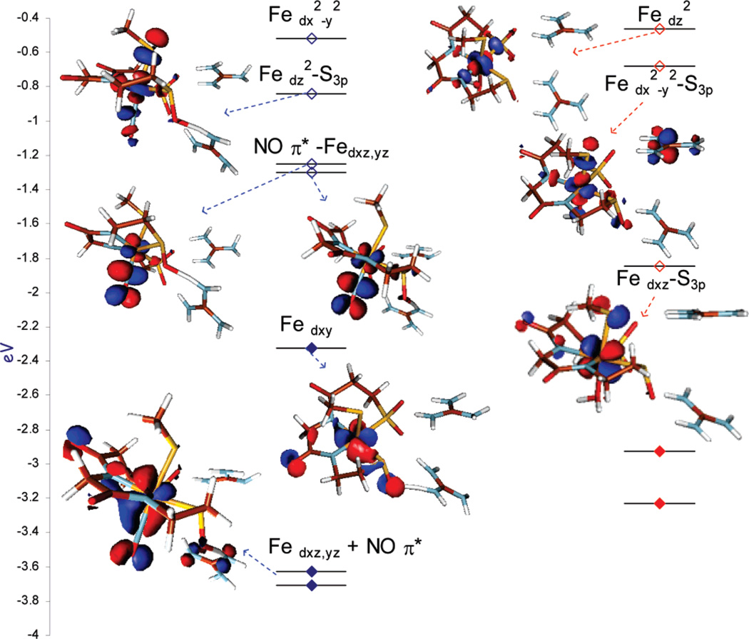
The MO diagrams of the NO-bound ([FeNO]6) and photolyzed NHase are given in Figure 8 (the β unoccupied orbitals). Figure 8 (right) shows that the NO-bound form has a formal t26 configuration. There are two unoccupied NO π* LUMOs and two higher-energy unoccupied e orbitals, dz2 and dx2–y2. The dz2 orbital (highlighted in blue) has 19% S3p character due to pseudo-σ (S3p orbital slightly tilted off the Fe–S bond as the angle C–S–Fe > 90°) overlap with the thiolate, which would provide the intensity for a single pre-edge feature, as observed in Figure 6 (inset) at 2470.1 eV. Photolysis cleaves the Fe–NO bond and creates a low-spin FeIII center with a H2O/OH− molecule coordinated in place of NO. Here the t2 hole is oriented by the strong axial CysS− donor into the d-π orbitals (shaded in red). This covalent mixing of the CysS− π into the d orbital leads to the new lower-energy feature at 2469.5 eV in the pre-edge of the photolyzed protein. The higher-energy e feature remains at 2470.2 eV, as the pseudo-σ overlap with this axial CysS− ligand does not change.
Figure 8.
DFT-calculated energy level diagram (β MO’s) of the NHase-NO active site (left) and NHase-photoactivated (right) (occupied orbitals are filled diamonds and unoccupied orbitals are open diamonds). The MO’s having S3p mixing will have pre-edge transition intensity.
The pre-edge region of the S K-edge XAS data is affected by the chemical nature of the ligand, the ligand field of the metal, and its Zeff. Here we use the pre-edge to probe the Zeff of the metal ion and thus obtain insight into its effective oxidation state. It is important to note that FeII complexes do not show a pre-edge transition, as the Zeff for the FeII is low and this shifts the Fe3d manifold of orbitals to higher energy, such that the RS−1s → Fe3d transitions overlap with the RS−1s → RS−C–Sσ* transition and are not distinguishable. The fit to the NHase data shows a small pre-edge feature at 2470.1 eV (Figure 5 inset, Table 2), which suggests that the Zeff of the Fe in the [FeNO]6 active site of NHase is significantly higher than that for low-spin FeII complexes59 and similar to that of FeIII NHase.
Discussion
S K-edge XAS is very sensitive to the chemical nature of the sulfur atom. In this study we have used structurally characterized synthetic model complexes to identify signature transitions corresponding to different types of sulfur ligands. Not only does the edge show dramatic differences upon oxidation; in the case of RSO− the edge is also sensitive to protonation. The data for both the NO-bound inactive and photolyzed active forms of the NHase enzyme show the presence of three types of sulfur ligands at the active site: CysS−, CysSOH, and CysSO2(H). Although we could not identify the protonation state of the CysSO2− using our data, DFT calculations in both the gas phase and PCM show that it is ionized (Figure 9). This model can now be used to understand the role of these oxidized cysteines in catalysis.
Figure 9.
Active-site model of NHase NO-bound form developed from S K-edge XAS and DFT calculations.
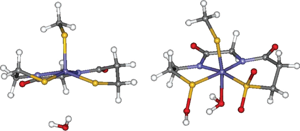
The oxidation of the cysteine ligands has been proposed to be catalytically relevant, either by affecting the binding of a nitrile, followed by a nucleophilic attack by H2O, or by affecting the binding of a H2O to the open coordination site of the Fe, which then ionizes to release a H+ that catalyzes the hydrolysis. A geometry-optimized DFT calculation on a low-spin FeIII NHase active site with three thiolates (Figure 10) and using H2O as the sixth ligand shows weak binding (Fe–OH2 = 3.4 Å) affinity. However, calculations with the oxidized ligand set show favorable H2O binding in this vacant coordination site (Fe–OH2 = 2.1 Å). Thus, the oxidized sulfur ligands are weaker donors, which will increase the Lewis acidity of the FeIII center and thus tune the ligand binding affinity to this vacant, catalytically relevant, exchangeable coordination site.
Figure 10.
(Left) H2O binding at a hypothetical NHase site where cysteines are not oxidized; Fe–O = 3.4 Å. (Right) H2O binding at the actual enzymatic site (Fe–O = 2.1 Å).
The electronic structure of linear [FeNO]6 units has been a major focus of research in bio-inorganic chemistry.60,61 Münck and co-workers, using Mössbauer spectroscopy, suggested that the electronic structure of the NO-bound NHase can be described as Fe(IV)-NO−.62 That conclusion was based on small isomer shifts (0.03–0.05 mm/s) and high quadrupole splittings (1.3–2.0 mm/s) observed for an [FeNO]6 model.63 However, the electronic properties of these complexes, investigated by recent DFT calculations, have suggested that this unit can be described as a low-spin Fe2+ coordinated to a NO+ unit.60,64 On photolysis, a low-spin FeIII center is produced which is well-characterized by EPR, Mössbauer, and resonance Raman spectroscopy.1,6 Note that, from the XAS near-edge transitions, we know that the chemical nature of the CysS− does not change upon photolysis, and hence it serves as a spectator of the change in Zeff of the Fe ion in this process. The pre-edge of this photolyzed ferric active site is observed at 2469–2470 eV (Figure 6, inset, dashed black), an energy very similar to that of the pre-edge of the inactive NO-bound form of NHase. This suggests that the Zeff of the Fe atom in the [FeNO]6 NHase active site is very similar to that of FeIII NHase rather than to that of FeII or FeIV. Also note that the second derivative of the NO-bound form (Figure 6 inset, black) has only one feature at 2470.1 eV, corresponding to one RS−1s → Fe3d (e) transition, while the second derivative of the photolyzed protein has an additional feature in the pre-edge at 2469.5 eV, corresponding to the creation of a new low-energy t2 hole in forming the low-spin FeIII center. This suggests that the [FeNO]6 unit of inactive NHase has a Zeff similar to that of FeIII but does not have a t2 hole. Such an electronic structure would be consistent with strong back-donation from the low-spin t26 iron to NO π* orbitals. From Figure 8, the inactive NO-bound form has a low-spin t26 iron center that has 28–31% back-bonding interaction with the NO (3d character summed over two unoccupied NO π* orbitals), which shifts charge density from the formally FeII and increases its Zeff.
Supplementary Material
Acknowledgment
This research was supported by NIH Grants NIH GM-40392 (E.I.S.), RR-01209 (K.O.H.), and GM45881 (J.A.K.) and by the Bioarchitect Research Program, RIKEN (M.O.). P.L.-M. gratefully acknowledges support from NIH Predoctoral Minority Fellowship F31-GM073583-01. SSRL operations are supported by the Department of Energy, Office of Basic Energy Sciences. The SSRL Structural Molecular Biology Program is supported by the National Institutes of Health, National Center for Research Resources, Biomedical Technology Program, and by the Department of Energy, Office of Biological and Environmental Research.
Footnotes
Supporting Information Available: Complete ref 47; optimized coordinates of complexes 1–4, free ligands, and the NO active site of NHase (in gas phase and using the PCM model). This material is available free of charge via the Internet at http://pubs.acs.org.
References
- 1.Endo I, Nojiri M, Tsujimura M, Nakasako M, Nagashima S, Yohda M, Odaka M. J. Inorg. Biochem. 2001;83:247–253. doi: 10.1016/s0162-0134(00)00171-9. [DOI] [PubMed] [Google Scholar]
- 2.Yamada H, Kobayashi M. Biosci. Biotechnol. Biochem. 1996;60:1391–1400. doi: 10.1271/bbb.60.1391. [DOI] [PubMed] [Google Scholar]
- 3.(a) Nagashima S, Nakasako M, Dohmae N, Tsujimura M, Takio K, Odaka M, Yohda M, Kamiya N, Endo I. Nat. Struct. Biol. 1998;5:347–351. doi: 10.1038/nsb0598-347. [DOI] [PubMed] [Google Scholar]; (b) Huang W, Jia J, Cummings J, Nelson M, Schneider G, Lindqvist Y. Structure. 1997;5:691–699. doi: 10.1016/s0969-2126(97)00223-2. [DOI] [PubMed] [Google Scholar]
- 4.Nagasawa T, Takeuchi K, Yamada H. Eur. J. Biochem. 1991;196:581–589. doi: 10.1111/j.1432-1033.1991.tb15853.x. [DOI] [PubMed] [Google Scholar]
- 5.Payne MS, Wu S, Fallon RD, Tudor G, Stieglitz B, Turner IM, Nelson MJ. Biochemistry. 1997;36:5447–5454. doi: 10.1021/bi962794t. [DOI] [PubMed] [Google Scholar]
- 6.Miyanaga A, Fushinobu S, Ito K, Shoun H. Eur. J. Biochem. 2004;271:429–438. doi: 10.1046/j.1432-1033.2003.03943.x. [DOI] [PubMed] [Google Scholar]
- 7.Watanabe N, Nakayama H, Odaka M, Kawano Y, Takio K, Kamiya N, Nagamune T, Endo I. J. Inorg. Biochem. 2001;86:475–475. [Google Scholar]
- 8.Odaka M, Fujii K, Hoshino M, Noguchi T, Tsujimura M, Nagashima S, Yohda M, Nagamune T, Inoue Y, Endo I. J. Am. Chem. Soc. 1997;119:3785–3791. [Google Scholar]
- 9.Endo I, Odaka M, Yohda M. Trends Biotechnol. 1999;17:244–248. doi: 10.1016/s0167-7799(99)01303-7. [DOI] [PubMed] [Google Scholar]
- 10.Noguchi T, Nojiri M, Takei K, Odaka M, Kamiya N. Biochemistry. 2003;42:11642–11650. doi: 10.1021/bi035260i. [DOI] [PubMed] [Google Scholar]
- 11.Murakami T, Nojiri M, Nakayama H, Odaka M, Yohda M, Dohmae N, Takio K, Nagamune T, Endo I. Protein Sci. 2000;9:1024–1030. doi: 10.1110/ps.9.5.1024. [DOI] [PMC free article] [PubMed] [Google Scholar]
- 12.Piersma SR, Nojiri M, Tsujimura M, Noguchi T, Odaka M, Yohda M, Inoue Y, Endo I. J. Inorg. Biochem. 2000;80:283–288. doi: 10.1016/s0162-0134(00)00076-3. [DOI] [PubMed] [Google Scholar]
- 13.Endo I, Nojiri M, Tsujimura M, Nakasako M, Nagashima S, Yohda M, Odaka M. J. Inorg. Biochem. 2001;83:247–253. doi: 10.1016/s0162-0134(00)00171-9. [DOI] [PubMed] [Google Scholar]
- 14.Mascharak PK. Coord. Chem. ReV. 2002;225:201–214. [Google Scholar]
- 15.Kobayashi M, Shimizu S. Eur. J. Biochem. 1999;261:1–9. doi: 10.1046/j.1432-1327.1999.00186.x. [DOI] [PubMed] [Google Scholar]
- 16.Boone AJ, Chang CH, Greene SN, Herz T, Richards NGJ. Coord. Chem. ReV. 2003;238:291–314. [Google Scholar]
- 17.Harrop TC, Mascharak PK. Acc. Chem. Res. 2004;37:253–260. doi: 10.1021/ar0301532. [DOI] [PubMed] [Google Scholar]
- 18.Grapperhaus CA, Patra AK, Mashuta MS. Inorg. Chem. 2002;41:1039–1041. doi: 10.1021/ic015629x. [DOI] [PubMed] [Google Scholar]
- 19.Kovacs JA. Chem. ReV. 2004;104:825–848. doi: 10.1021/cr020619e. [DOI] [PMC free article] [PubMed] [Google Scholar]
- 20.Shearer J, Kung IY, Lovell S, Kaminsky W, Kovacs JA. J. Am. Chem. Soc. 2001;123:463–468. doi: 10.1021/ja002642s. [DOI] [PMC free article] [PubMed] [Google Scholar]
- 21.Shearer J, Jackson HL, Schweitzer D, Rittenberg DK, Leavy TM, Kaminsky W, Scarrow RC, Kovacs JA. J. Am. Chem. Soc. 2002;124:11417–11428. doi: 10.1021/ja012555f. [DOI] [PMC free article] [PubMed] [Google Scholar]
- 22.Noveron JC, Olmstead MM, Mascharak PK. J. Am. Chem. Soc. 2001;123:3247–3259. doi: 10.1021/ja001253v. [DOI] [PubMed] [Google Scholar]
- 23.Tyler LA, Noveron JC, Olmstead MM, Mascharak PK. Inorg. Chem. 2003;42:5751–5761. doi: 10.1021/ic030088s. [DOI] [PubMed] [Google Scholar]
- 24.Solomon EI, Hedman B, Hodgson KO, Dey A, Szilagyi RK. Coord. Chem. ReV. 2005;249:97–129. [Google Scholar]
- 25.Glaser T, Hedman B, Hodgson KO, Solomon EI. Acc. Chem. Res. 2000;33:859–868. doi: 10.1021/ar990125c. [DOI] [PubMed] [Google Scholar]
- 26.Neese F, Hedman B, Hodgson KO, Solomon EI. Inorg. Chem. 1999;38:4854–4860. doi: 10.1021/ic990461p. [DOI] [PubMed] [Google Scholar]
- 27.Szilagyi RK, Bryngelson PA, Maroney MJ, Hedman B, Hodgson KO, Solomon EI. J. Am. Chem. Soc. 2004;126:3018–3019. doi: 10.1021/ja039106v. [DOI] [PubMed] [Google Scholar]
- 28.George SD, Metz M, Szilagyi RK, Wang HX, Cramer SP, Lu Y, Tolman WB, Hedman B, Hodgson KO, Solomon EI. J. Am. Chem. Soc. 2001;123:5757–5767. doi: 10.1021/ja004109i. [DOI] [PubMed] [Google Scholar]
- 29.Szilagyi RK, Lim BS, Glaser T, Holm RH, Hedman B, Hodgson KO, Solomon EI. J. Am. Chem. Soc. 2003;125:9158–9169. doi: 10.1021/ja029806k. [DOI] [PubMed] [Google Scholar]
- 30.Anxolabéhère-Mallart E, Glaser T, Frank P, Aliverti A, Zanetti G, Hedman B, Hodgson KO, Solomon EI. J. Am. Chem. Soc. 2001;123:5444–5452. doi: 10.1021/ja010472t. [DOI] [PubMed] [Google Scholar]
- 31.Dey A, Glaser T, Moura JJG, Holm RH, Hedman B, Hodgson KO, Solomon EI. J. Am. Chem. Soc. 2004;126:16868–16878. doi: 10.1021/ja0466208. [DOI] [PubMed] [Google Scholar]
- 32.Glaser T, Bertini I, Moura JJG, Hedman B, Hodgson KO, Solomon EI. J. Am. Chem. Soc. 2001;123:4859–4860. doi: 10.1021/ja0155940. [DOI] [PubMed] [Google Scholar]
- 33.Hedman B, Frank P, Gheller SF, Roe AL, Newton WE, Hodgson KO. J. Am. Chem. Soc. 1988;110:3798–3805. [Google Scholar]
- 34.Lugo-Mas P, Xu L, Davin SD, Benedict J, Kaminsky W, Kovacs JA. J. Am. Chem. Soc. doi: 10.1021/ja062706k. submitted. [DOI] [PMC free article] [PubMed] [Google Scholar]
- 35.Nojiri M, Yohda M, Odaka M, Matsushita Y, Tsujimura M, Yoshida T, Dohmae N, Takio K, Endo I. J. Biochem. 1999;125:696–704. doi: 10.1093/oxfordjournals.jbchem.a022339. [DOI] [PubMed] [Google Scholar]
- 36.Shadle SE, Hedman B, Hodgson KO, Solomon EI. Inorg. Chem. 1994;33:4235–4244. [Google Scholar]
- 37.Agarwal BK. X-ray Spectroscopy. Berlin: Springer-Verlag; 1979. p. 276 ff. [Google Scholar]
- 38.Tyson TA, Roe AL, Frank P, Hodgson KO, Hedman B. Phys. ReV. B. 1989;39A:6305–6315. doi: 10.1103/physrevb.39.6305. [DOI] [PubMed] [Google Scholar]
- 39.Baerends EJ, Ellis DE, Roos P. Chem. Phys. 1973;2:41–51. [Google Scholar]
- 40.te Velde G, Baerends EJ. Int. J. Comput. Phys. 1992;99:84–98. [Google Scholar]
- 41.Vosko SH, Wilk L, Nusair M. Can. J. Phys. 1980;58:1200–1211. [Google Scholar]
- 42.Becke AD. Phys. ReV. A: Gen. Phys. 1988;38:3098–3100. doi: 10.1103/physreva.38.3098. [DOI] [PubMed] [Google Scholar]
- 43.Perdew JP. Phys. ReV. B. 1986;33:8822–8224. doi: 10.1103/physrevb.33.8822. [DOI] [PubMed] [Google Scholar]
- 44.Mulliken RS. J. Chem. Phys. 1955;23:1833–1840. [Google Scholar]
- 45.Gorelsky SI. AOMix Program rev.6.04. ( http://www.sg-chem.net). [Google Scholar]; Gorelsky SI, Lever ABP. J. Organomet. Chem. 2001;635:187–196. [Google Scholar]
- 46.Becke AD. J. Chem. Phys. 1993;98:5648–5652. [Google Scholar]
- 47.Frisch MJ, et al. Gaussian 03, Revision C.02. Wallingford CT: Gaussian, Inc.; 2004. [Google Scholar]
- 48.Miertus S, Scrocco E, Tomasi J. Chem. Phys. 1981;55:117–129. [Google Scholar]
- 49.The S K-edge XAS of free ligands having varying oxidation states is given in Figure S1 in the Supporting Information for reference. These results were published in ref 33.
- 50.XAS data for a stable uncoordinated RSO− species were unavailable, so we used the model complex data to identify the spectroscopic feature of this ligand.
- 51.The calculated S3p characters were scaled up by an approximate factor of 2 for every two units of change in its oxidation number to account for the increase in Zeff, which will increase the transition dipole integral, i.e. 〈S1s|r|S3p〉, leading to an increase in absorption intensity.
- 52.This transition is not shifted in energy in the CH3SO− fragment having the geometric parameters of complex 2, but is shifted (by 1.6 eV) to 8.9 eV in 2, reflecting the shift of charge from the coordinated sulfur atom due to covalent interaction, as also observed in complex 3.
- 53.The optimized S–O bond in 2 is 0.04 Å longer than in the crystal structure, while those for 3 and 4 are within 0.01 Å (Table 1).
- 54.Note that there is a minimum in the protein XAS data at 2474 eV, which may originate from RSO−1s → RSO−S–Oσ*. However, in the presence of nine methionine residues this feature is not observed in the absorption data.
- 55.The central C of the C(NH2)3+ species was frozen during optimization.
- 56.Okuyama T, Miyake K, Fueno T, Yoshimura T, Soga S, Tsukurimichi E. Heteroat. Chem. 1992;3:577–583. [Google Scholar]
- 57.Given the resolution of the crystal structure, it is not possible to distinguish between calculated structures B (ε = 0) and C (ε = 4.0) using structural parameters.
- 58.Estimated using the crystal structure of NO bound Nhase (pdb id 2AHJ) with the software PROPKA: Li H, Robertson AD, Jensen Jan H. Proteins. 2005;61:704–721. doi: 10.1002/prot.20660.
- 59.The absence of a pre-edge feature in FeII sites has been studied in complexes with weak field ligands (Cl− RS−). Here, the 3d manifold in the NHase-NO complex will be further shifted to higher energy by the strong amide and NO donors. Hence, the pre-edge transition will shift deeper into the RS1s → RSC–Sσ* transitions of the rising edge. Thus, the spin state cannot account for the low pre-edge energy.
- 60.Serres RG, Grapperhaus CA, Bothe E, Bill E, Weyhermüller T, Neese F, Wieghardt K. J. Am. Chem. Soc. 2004;126:5138–5153. doi: 10.1021/ja030645+. [DOI] [PubMed] [Google Scholar]
- 61.Tomita T, Haruta N, Aki M, Kitagawa T, Ikeda-Saito M. J. Am. Chem. Soc. 2001;123:2666–2667. doi: 10.1021/ja001431k. [DOI] [PubMed] [Google Scholar]
- 62.Popescu V-C, Münck E, Fox BG, Sanakis Y, Cummings JG, Turner IM, Jr, Nelson MJ. Biochemistry. 2001;40:7984–7991. doi: 10.1021/bi010198f. [DOI] [PubMed] [Google Scholar]
- 63.Hauser C, Glaser T, Bill E, Weyhermuller T, Wieghardt K. J. Am. Chem. Soc. 2000;122:4352–4365. [Google Scholar]
- 64.Greene SN, Richards NGJ. Inorg. Chem. 2004;43:7030–7041. doi: 10.1021/ic0499695. [DOI] [PubMed] [Google Scholar]
Associated Data
This section collects any data citations, data availability statements, or supplementary materials included in this article.


