Abstract
A brass-platinum electrochemical micro flow cell was developed to extract [18F]fluoride from an aqueous solution and release it into an organic based solution, suitable for subsequent radio-synthesis, in a fast and reliable manner. This cell does not suffer electrode erosion and is thus reusable while operating faster by enabling increased voltages. By optimizing temperature, trapping and release potentials, flow rates, and electrode materials, an overall [18F]fluoride trapping and release efficiency of 84±5% (n=7) was achieved. X-ray photoelectron spectroscopy (XPS) was used to analyze electrode surfaces of various metal-metal systems and the findings were correlated with the performance of the electrochemical cell. To demonstrate the reactivity of the released [18F]fluoride, the cell was coupled to a flow-through reactor and automated synthesis of [18F]FDG with a repeatable decay-corrected yield of 56±4% (n=4) was completed in <15 min. A multi-human dose of 5.92 GBq [18F]FDG was also demonstrated.
Keywords: Electrochemical Cell, PET, [18F]Fluoride, Radiochemistry, FDG, Flow Reactor
Introduction
Chemical reactions such as radiofluorination and deprotection have been observed to proceed remarkably quickly within flow-through microfluidic devices (Brivio et al., 2006)(Gillies et al., 2006)(Steel et al., 2007), promising ultra-fast production of short-lived tracers for positron emission tomography (PET). These devices can be used to achieve rapid synthesis times while providing a highly controlled reaction environment which, combined with protection from air and moisture, makes them ideal candidates for automated PET radiosynthesis. Flow-through systems capable of nearly every process in a multi-step synthesis have been reported (Sahoo et al., 2007) and have even reached the commercial marketplace (Palmieri et al., 2009), but conventional vial-based modules are still used to remove water from [18F]fluoride and perform other solvent-exchange processes. The combination of both microfluidic and conventional elements often makes the overall systems more complex than their conventional counterparts. Furthermore, the loss of activity associated with the drying and reconstitution of [18F]fluoride in a vial, as well as its subsequent transfer to the microreactor can be circumvented by avoiding the traditional azeotropic evaporation step (Lemaire et al., 2010).
In conventional systems, water is typically removed from [18F]fluoride via a combination of solvent-exchange on a quaternary methyl ammonium (QMA) cartridge followed by several steps of azeotropic distillation prior to nucleophilic fluorination. Miniaturized versions of conventional methods have been implemented in sophisticated batch microfluidic devices (Lee et al., 2005)(Elizarov et al., 2010)(Bejot et al., 2011)(Keng et al., 2012), but due to the absence of valves in lower-cost and simpler flow-through microfluidics, such processes cannot readily be implemented. An alternative drying method based on solvent-exchange within an electrochemical cell has been reported (Hamacher et al., 2002) and has recently been implemented in a microdevice (Saito et al., 2007). The dried [18F] fluoride is reactive and can be directly used for the production of radiotracers without the need for any evaporation steps by connecting the output of the cell to one input of a microreactor (Wong et al., 2012). Aside from the convenience of integration, electrochemical separation of [18F] fluoride from water offers additional advantages such as faster drying, complete dehydration of the adsorbed fluoride ions without the need for repeated azeotropic drying and potential use of the platform for monitoring residual water concentration in the cell (Sadeghi et al., 2012).
To date, there have been reports that have investigated the effects of various carbon electrode geometries on the fluoride extraction and release. All existing electrochemical solvent exchange approaches use glassy carbon or graphite as the anode electrode as in the very first experiments (Alexoff et al., 1989) in combination with a metal cathode (usually platinum). However, glassy carbon surfaces degrade with use, resulting in low efficiencies and large deviations in trap and release after multiple experiments (Sadeghi et al., 2010). In addition, the erosion of the glassy carbon can be associated with the release of particulates and clogging of downstream microfluidic components, adversely affecting the performance and reliability of the synthesis (Saiki et al., 2010).
We report here an electrochemical cell with two metal electrodes that obviate these shortcomings. We investigated a number of different metals, observing marked differences in performance of trapping from water and release into an organic solvent dependent on the nature of the metal. This is consistent with reports that halide ion adsorption on metal electrodes is related to oxide and bond formation (Endo et al., 1999)(Piasecki et al., 2010). X-ray photoelectron spectroscopy (XPS) analysis of the surfaces of several metals used in the electrochemical cell provides some insight into the unique fluoride adsorption and desorption properties. The performance of the device shows a relation to the surface oxides, depth of intercalation, and the nature of chemical bonds formed on the surface during the electrochemical process. By avoiding the use of glassy carbon, the rapid electrode erosion is eliminated, making the cell reusable with consistent performance. Furthermore, operation at higher voltages (which improves trapping speed (Yamahara et al., 2007) but would have accelerated the erosion of glassy carbon) is possible, allowing efficient trapping at much faster speeds compared with that of glassy carbon. With an anodic potential of 20 V, a brass-platinum cell was able to adsorb greater than 95% of [18F] fluoride from 1.5 mL of water in less than 30 sec. The same cell was used in more than 100 experiments over a period of several months with only a minor decrease in performance and no need for replacement or repair. The driving system incorporates feedback mechanisms comprising optical and electrical signals to determine the completion of certain steps and the synchronization of flows. To confirm the reactivity of the released [18F] fluoride from the all-metal electrochemical cell, we coupled the cell to a custom-built flow reactor and produced 2-[18F]fluoro-2-deoxy-D-glucose ([18F]FDG) in less than 15 min. Decay-corrected radiochemical yield of 56% with activity levels up to several GBq were produced from this platform, which is sufficient for multiple human doses.
Experimental
Electrochemical flow-cell
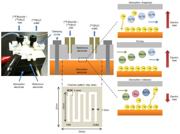
The electrochemical flow cell (Fig. 1) is a multi-layer structure comprised of a cut polymer film clamped between two rigid electrodes. A serpentine channel pattern (1.5 mm × 121 mm) was die-cut by CS Hyde (Lake Villa, Ill) out of a double-sided adhesive PTFE tape (250 μm thickness) giving a fluid path of 46 μL volume. Fabrication by xurography was also investigated but the die-cutting method produced higher quality cut films with more reproducible dimensions and smoother channel walls. The electrodes were fabricated by computer numerical control (CNC) machining of brass blocks. The anode (bottom) was used as is, or was covered with various metal foils for the comparison of performances. The cathode (top) was electroplated with platinum (2.5 μm by Silvex Inc., Westbrook, ME). Layers were clamped together by electrically-insulated screws to form a liquid-tight seal between the polymer film and the two electrodes.
Figure 1.
(Left)Platinum-transition metal electrode cell assembled with fluidic and electrical connections.(Top center) Cross section of the flow cell. A patterned adhesive layer defining the fluid path (Bottom center) is sandwiched between an adsorption electrode and a reference electrode. Fluid follows a serpentine path to maximize the time spent within the electric field between the two electrodes. During trapping (top right), the negatively-charged [18F]fluoride ions are attracted to the positively-charged adsorption electrode and adsorb to the surface while the [18O]water continues to the outlet. (Middle right) [18F]fluoride is dried using an anhydrous solvent. (Bottom right) [18F]fluoride is released into a solution suitable for downstream radiochemical synthesis while applying a (generally smaller) reverse potential.
The anode and cathode were connected to a custom-designed voltage/current amplification circuit capable of supplying −20 V to +20 V at a current up to 50 mA and a frequency from DC to 10 kHz. Current through the liquid in the cell was measured by incorporating in series a negligible 1 Ω shunt resistor acting as a current-to-voltage converter with a conversion factor of 100 mV/mA.
Cartridge heaters (Watlow, Torrance, CA) and a thermocouple (HTTC36-K-116U-1.5-GG, Omega, Stamford, CT) embedded in the cell were connected to a temperature controller (CN7500, Omega, Stamford, CT) to maintain elevated temperature during the [18F]fluoride trap and release.
Materials and reagents
Metal foils for anodes, including zinc (200 μm thick, 99.9% metals basis), silver (125 μm, 99.9%), copper (500 μm, 99.98%), gold (25 μm, 99.99%), and nickel (500 μm, 99.98%), were obtained from Sigma Aldrich (Milwaukee, WI). Brass alloy 360 (with a composition of 61.5% copper, 2.5% lead, 0.35% iron and 35.5% zinc) was obtained from McMaster-Carr (Los Angeles, CA). Havar (25 μm) with a composition of Co 41.6%, Mo 2.20%, Cr 19.5%, Si 0.08%, Ni 12.5%, Mn 1.59%, W 2.59%, C 0.20%, Fe balance and Tantalum (25 μm, 99.8%) were from Hamilton Precision Metals (Lancaster, PA).
Solvents and chemicals, including acetonitrile (MeCN), ethanol (EtOH), ethyl acetate (EtOAc), hexane, 1,3,4,6-tetra-O-acetyl-2-O-trifluoromethanesulfonyl-β-D-mannopyranose (mannose triflate), potassium carbonate (K2CO3), potassium fluoride (KF) and 4,7,13,16,21,24-hexaoxa-1,10-diazabicyclo[8.8.8]hexacosane (Kryptofix K222, K-222) were obtained from Sigma Aldrich (Milwaukee, WI) and used without further purification.
tC18 Sep-Pak cartridge with particle sizes of 55-105 μm and anion exchange resin cartridge with mass of 360 mg were obtained from Waters (Milford, MA). KT-100 FDG purification cartridges for base hydrolysis were obtained from Isoflex, (San Francisco, CA).
No-carrier added [18F]fluoride was produced in a RDS-111 (Siemens, USA) cyclotron by proton bombardment of 18O-enriched water ([18O]H2O, Rotem, Inc., Israel). [18F]fluoride was flowed through the cell without additional treatment.
The solution to release the trapped [18F]fluoride consisted of K-222 (26 mM) and K2CO3 (13 mM) in MeCN containing 0.6% water to ensure solubility.
Selection of the anode electrode material
To find a suitable anode material, several group 10-12 transition metals were investigated in addition to brass. These metals included gold, silver, zinc, nickel, and copper. Films of havar, and tantalum were also tested since their use as cyclotron target materials for [18O]water bombardment has been demonstrated to enable a high extraction of [18F]fluoride without adversely affecting its reactivity (Satyamurthy et al., 2002), thus suggesting the potential for efficient desorption from these metals. For anode comparisons, 500 μL of aqueous [18F]fluoride was flowed through the cell at a flow rate of 6 mL/min with the application of a 20 V anodic potential. After trapping, the cell was flushed with 2 mL of MeCN at a flow rate of 6 mL/min for 20 sec and dried with argon at 20 psi (138 kPa) for 10 sec. The trapped [18F]fluoride was released into 833 μL of release solution flowed at 0.5 mL/min with an applied potential of −2.0 V at room temperature.
Optimization of [18F]fluoride trap and release
The trap and release system is shown on the left in Fig. 2. The fluid inlet of the cell was connected to two computer-controlled syringe pumps (PSD-4, Hamilton, Reno, NV) in series. The pump closest to the cell is connected to a vial of [18F]fluoride releasing solution. The second pump is connected to a source of argon gas, and via a computer-controlled selection valve (MXP7970, Rheodyne, Pompton Plains, NJ) to (i) a vial of [18F]fluoride in [18O]H2O, (ii) a vial of anhydrous acetonitrile (MeCN) for removing water, and (iii) a vial of deionized water for washing the cell between experiments. To monitor the trap and release efficiencies, the cell was placed inside a dose calibrator (CRC-25 PET, Capintec, Inc., Ramsey, NJ). The output of the cell was connected to a three-way valve that could be directed to a waste vial (located inside a second and identical dose calibrator) or to the downstream system (either a collection vial or the synthesizer). All components were connected to a PC via a 14-bit data acquisition module (USB6009, National Instruments, Austin, TX), and controlled via a custom program written in Labview (National Instruments, Austin, TX). The software was optimized to receive, analyze, store, and provide control parameters with all devices within a 30 msec iteration to provide real-time control and enable the use of feedback information to control flow timing during radiosynthesis.
Figure 2.
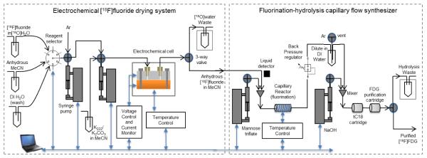
Schematic of the control and measurement system for the electrochemical flow cell (left) and flow-through radiosynthesizer (right). Blue arrows indicate the control of the components via a personal computer.
PEEK tubing (750 μm I.D., 1.6 mm O.D., IDEX Health & Science, Oak Harbor, WA) was used to plumb most of the system to avoid adverse effect on specific activity as can occur with the use of Teflon tubing (Berridge et al., 2009). Teflon® PFA tubing (750 μm I.D., 1.6 mm O.D., IDEX Health & Science, Oak Harbor, WA) was used as a replacement for PEEK in a short segment that passes through the optical liquid detector.
[18F]fluoride was adsorbed on the anode by pumping the initial solution through a temperature controlled cell (room temperature or 65 °C) while an anodic potential (0, 5, 10, or 20 V) was applied. The flow rate (0.7, 1.7, 2, 4 or 6 mL/min) was controlled via a syringe pump. Next, the cell was flushed at 6 mL/min with 2 mL of MeCN (collected in a waste vial) and dried with argon for 10 sec at 20 psi. These parameters caused negligible loss of radioactivity from the cell. The release of the [18F]fluoride into the solution of K-222, K2CO3 and MeCN and 0.6% H2O was performed by applying a cathodic potential (−2.0, −2.5, −3.0, −3.5, −5.0 or −10 V), at a flow rate of 0.5, or 1.0 mL/min.
Autoradiography was used for imaging the spatial profile of trapped [18F]fluoride on the anode electrode. The cell was disassembled after trapping and covered with a thin ~10μm plastic wrap. Four hours after trapping the electrode was exposed for 30 seconds to phosphor imaging plates (Fujifilm, USA) and imaged with the FUJI BAS 5000 (Fuji Systems Inc., USA) phosphor imaging system, which produces autoradiograms with a resolution as high as 25 microns.
After each experiment, the cell was regenerated and cleaned by applying a −2.0 V (cathodic) potential while 6 mL of deionized water flowed through the chip at (2 mL/min). The application of the relatively small cathodic potential was designed to clean the metal surface of remnant oxides that could have formed during the adsorption process, but not cause the formation of metal smut and plating on the electrode surface that can result at high cathodic potentials.
Measurements of the radioactivity in the electrochemical cell were made before and after trapping, Rcell(0) and Rcell(trap), respectively, and then again after release, Rcell(release). Similarly, measurements of the radioactivity in the waste vial were made before and after trapping, Rwaste(0) and Rwaste(trap), respectively, and then again after release, Rwaste(release). Trapping efficiency, etrap, was computed as:
Release efficiency, erelease, was computed as:
Flow reactor and synthesis of [18F]FDG
To confirm the reactivity of the [18F]fluoride solution trapped and released from the cell, the cell was coupled to a custom-built synthesis apparatus, as shown on the right of Fig. 2 using a synthesis protocol adapted from (Wester et al., 2009). In detail, 500 μL of aqueous [18F]fluoride was allowed to flow through the heated electrochemical cell (65 °C) at a flow rate of 6 mL/min with the application of a 20 V anodic potential. After trapping, the cell was flushed with 2 mL of MeCN at a flow rate of 6 mL/min for 20 sec and dried with argon at 20 psi for 10 sec. The trapped [18F]fluoride was released into 833 μL of release solution which flowed at 1.0 mL/min with an applied potential of −2.0 V.
The [18F] fluoride solution released from the electrochemical cell was mixed with 1.0 mL of 30 mM solution of mannose triflate (in MeCN) via a Y-junction mixer. Each solution passed at a flow rate of 1 mL/min, controlled by the computer-controlled syringe pump. An optical liquid detector positioned upstream of the Y-junction mixer was used to detect the arrival of the [18F]fluoride solution and ensure the mannose triflate flow reached the mixer just prior to the [18F]fluoride solution. The mixed solution, with a total flow rate of 2.0 mL/min was subsequently directed through the flow through reactor heated to 110 °C to produce 2-deoxy-2-[18F]fluoro-1,3,4,6-tetra-O-acetyl-beta-D-glycopyranose ([18F]FTAG). The reactor consist of 76 cm of PEEK tubing coiled around a grooved metal cylinder with an embedded cartridge heater (Watlow, Torrance, CA) and a thermocouple (HTTC36-K-116U-1.5-GG, Omega, Stamford, CT) controlled via a temperature controller (CN7500, Omega, Stamford, CT). The fluorination reaction time of the mixture in the chip was approximately 15 sec. A back-pressure regulator set at 100 psi (0.689 MPa) prevented the formation of vapor bubbles in the super-heated solution. Following the fluorination step, the output of the flow reactor was bubbled into a vial pre-filled with 20 mL of deionized water. Two mL of MeCN, at a flow rate of 2.0 mL/min, was used to flush the flow through reactor. The diluted mixture was then pushed by pressurized argon at 20 psi (138 kPa) through a tC18 Sep-Pak cartridge. The tC18 cartridge was preconditioned with 10 mL of EtOH, 10 mL of H2O, and a single 10 mL push of air. Effluent was collected in a waste container. Base hydrolysis proceeded on the tC18 cartridge at room temperature by passing 1 mL of 2 M NaOH followed by 10 mL of water at 5 mL/min. For the neutralization and purification of the end product, a FDG purification cartridge (Isoflex, San Francisco, CA) preconditioned with 10 mL of EtOH, 10 mL of H2O, and a single 10 mL push of air was located directly in-line with the outlet of the tC18 cartridge. The resulting purified [18F]FDG was collected in a vial at the end of the reaction.
Two samples of the collected [18F]FDG were analyzed by radio thin layer chromatography (radio-TLC) with a radio-TLC scanner (miniGITA, Raytest, Wilmington, NC) to determine the radiochemical yield and purity. Alumina TLC plates (Sigma-Aldrich, Milwaukee, WI) were used as the stationary phase and the two different mobile phases were (i) 95:5 (v/v) MeCN and H2O and (ii) 50:50 (v/v) hexane and ethyl acetate. The hexane-ethyl acetate condition gave a reliable measure of the fluorination yield while the MeCN-water condition gave a reliable measure of the completeness of the hydrolysis (Hamacher et al., 2002). Contents of the waste vials and intermediate vials were measured in a dose calibrator and also analyzed by radio-TLC to determine their composition. Residual activity in the cartridges was measured in a dose calibrator. The calculation of the yield and the reaction efficiencies derived from the dose calibrator and TLC data are explained in detail in the Supplementary Material.
X-Ray Photoelectron Spectroscopy (XPS) studies
X-ray photoelectron spectroscopy (XPS) measurement of surfaces were performed after trapping to investigate whether differences in the interaction of fluoride at the surface were correlated with differences in trap and/or release performance. Radioactive fluorine-18 could not be used in our XPS setup, so to prepare the electrodes for surface analysis with XPS, aqueous KF (10 mM) was passed through the cell while a +20 V potential was applied. To repeat the experimental conditions used for [18F]fluoride trapping, multiple flushes with MeCN were performed subsequently to remove residual water. The chip was carefully disassembled following adsorption, washed with isopropanol, and transferred to the XPS vacuum chamber within 15 min. The washing of the chip with isopropanol was found not to have an effect on the fluoride peak but reduced noise in the spectra presumably by eliminating some contaminants.
XPS spectra were acquired on a Kratos Axis ultra XPS spectrometer at the Materials Characterization Laboratory of the UCLA Molecular Instrumentation Center. An aluminum monochromated X-ray source operating at 10 mA and 15 kV (150 W) was focused on the sample surface. The hybrid analysis mode was used which provided a sampling area of 300 × 700 μm. A pre-aligned optical camera was used to analyze the area of interest and the flow path was verified by the substrate metal and the F1s peak. Sample height was optimized by maximizing the C1s peak. Survey spectra were acquired at 160 eV pass energy and region spectra were acquired at 80 eV pass energy. The instrument vacuum was maintained at <10−8 Torr. To investigate the elemental compositions below the surface, experiments were performed on subsurface material by ablating away the surface layers using argon ion milling (operating at 15 mA and 5 kV, with an estimated etch rate of approximately 50 Å/min. The CASA XPS software package (Casa Software Ltd., UK) was used for data fitting and analyzing the core-level spectra. A Shirley background was subtracted and a Marquardt peak-fitting procedure was applied using Gaussian-Lorentzian curves. The relative concentrations of pertinent chemical elements were determined from the area of core-level peaks taking into account the sensitivity coefficients of each element.
Results and discussion
Selection of anode electrode material
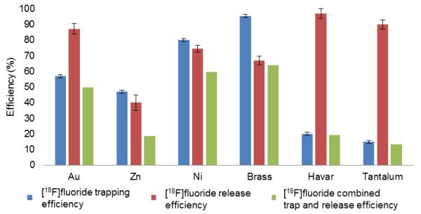
The performance of [18F]fluoride adsorption and release for several different electrode materials is shown in Fig. 3. Brass exhibited the highest overall efficiency (etrap × erelease) of 63% compared to Au (50%), Zn (19%), Ni (59%), Havar and tantalum (both less than 20%), and was therefore selected as the anode material for subsequent experiments. As expected, Havar and tantalum exhibited high release efficiencies (both greater than 90%) but the trapping efficiencies were extremely low. The results presented for the gold electrode were made possible by increasing the adsorptivity of the [18F]fluoride anion by the addition of 50 μL of EtOH and 500 μL of MeCN to 500 μL of irradiated [18O]water. Under the condition of a slower flow rate (1 mL/min), up to 80% of [18F]fluoride anions could be absorbed. Though promising, these efforts were abandoned in favor of the simpler and faster alternative of using brass. Copper and silver could not be properly tested in the flow through cell as significant oxidation led to clogging and frequent flow cell blockage.
Figure 3.
Comparison of trap and release performances of Au, Zn, Ni, Brass, Havar, Tatalum as anode material. Error bars indicate the standard error of the mean. Cu and Ag could not be properly tested as significant oxidation led to frequent clogging of the flow through system.
Optimization of [18F]fluoride trap and release parameters
After the selection of brass as the anode, other parameters optimized were the trapping and release potentials, flow rates, and temperatures. Temperature was tested as it was suspected that the process of adsorption and release is partially chemical in nature and not purely coulombic. All parameters were chosen with the additional constraint of completing the steps in the least amount of time.
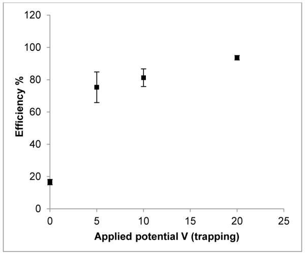
As trapping requires the migration of the [18F]fluoride ions to the anode, trapping is expected to be improved at higher potentials. At room temperature, an anodic trapping potential of +20 V resulted in the highest trapping efficiency of 94±2% (std. error; n = 49) compared to that of 16±2% at 0 V (n = 4) (Fig. 4). Although +5 and +10 V also had relatively high trapping efficiencies of 75±10% (n=6) and 81±6% (n=17), respectively, the errors were also greater. Therefore, +20 V was chosen as the optimum potential for trapping. Figure 5 shows an autoradiography image of the chip after trapping at +20V, showing that most of the [18F]fluoride is trapped before the last couple of turns of the channel. At lower voltages it is likely that some of the [18F]fluoride flows out of the cell before the ions have had time to migrate to the anode, thus reducing the trapping efficiency. Though the trend of increased trapping with increased potential suggests improved performance even beyond +20 V, our power supply was limited to +20 V. The non-zero trapping efficiency at 0 V supports the view that the interaction between the fluoride and the brass anode is also partially chemical in nature.
Figure 4.
The effect of the applied electrochemical cell potential (0, 5, 10 and 20 V) on the trapping efficiency of [18F]fluoride using a brass anode. Error bars are ±1 std. error. N for 0, 5, 10 and 20 V are 4, 6, 17 and 49, respectively.
Figure 5.
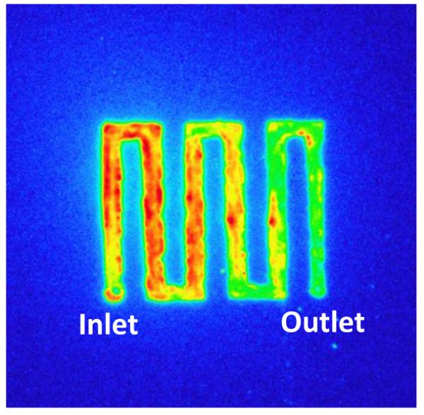
Autoradiography image, shows the spatial profile of the trapped [18F]fluoride on the brass anode surface after trapping at +20V and 6 mL/min. The colour scale of blue, green, yellow, red represents increasing radioactivity.
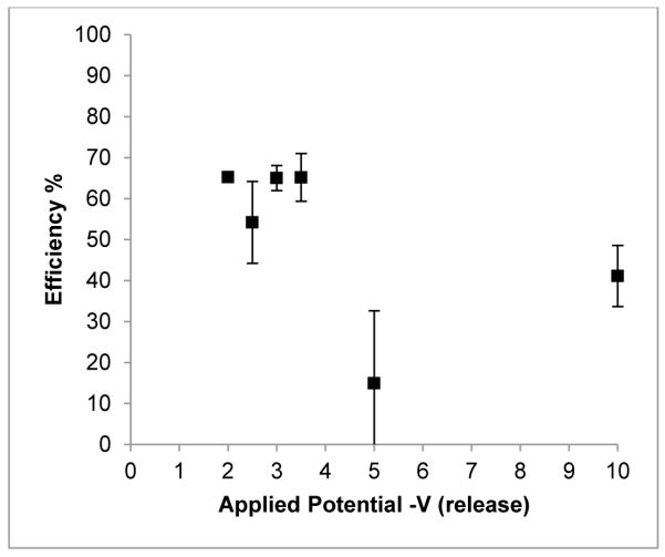
At room temperature, a cathodic release potential between −2.0, and −3.5 V produced the highest release efficiency which then dropped from an average of 61% to 30% at −5 and −10 V (Fig. 6). As no apparent difference was observed between −2.0 and −3.5 V the lower voltage was chosen because of better reproducibility of results and to decrease the chances of deleterious electrochemical reactions.
Figure 6.
The effect of the applied electrochemical cell potential (−2, −2.5, 3, −3.5, −5 and −10 V) on the release efficiency of [18F]fluoride using a brass electrode. N = 24 for −2 V, n = 4 for other potentials. Error bars are ±1 std.error.
The influence of temperature and solvent flow rates during the adsorption and the release steps were performed in tandem. At room temperature, the trapping of [18F]fluoride at +20 V between the flow rates of 0.7 to 6.0 mL/min had efficiencies ranging from 86 to 95%. The trapping efficiency at an elevated temperature of 65 °C ranged between 91 and 95%. The highest trapping efficiencies were achieved at a flow rate of 0.7 mL/min at room temperature and 6 mL/min at 65 °C, at 95±4% (n=9) and 95±4% ( n=13), respectively. Therefore, for the trapping process, the highest flow rate of 6 mL/min was used in conjunction with an elevated temperature of 65 °C to minimize the trapping time. While high flow rate decreases trapping time, we expect there to be an upper limit where the flow is too fast to allow sufficient time for [18F]fluoride ions to migrate to and interact with the anode. This limit was not reached in the range of flow rates tested at 65 °C.
For the release of [18F]fluoride, flow rates of 0.5 mL/min and 1.0 mL/min, were tested. The release efficiencies at room temperature were 70±5% and 77±6%, respectively (ave.±std.dev., n=9). From these results, the higher flow rate of 1.0 mL/min was chosen to reduce the time for this process and as there was no observable difference in release efficiencies. For the temperature of release, the efficiency at room temperature and 65 °C were 75±6% and 84±5 %, respectively (ave.±std.dev., n = 16). As such, a temperature of 65 °C was chosen.
From all of the optimization results, it was concluded that the best parameters to use for trap and release of [18F]fluoride in our electrochemical cell with a brass anode are at a temperature of 65 °C, with an applied potential of +20 V and flow rate of 6 mL/min during trapping, and an applied potential of −2 V and flow rate of 1.0 mL/min during release. With these settings, final trap and release efficiencies of 95±4% and 88±3% (ave.±std.dev., n = 7), respectively, were attained. The combined efficiency is 84±5% at these settings, which is significantly different from that of 60±20% prior to optimization (t = 5.42, df = 30 at p = 0.001). Compared to previous studies (Hamacher and Coenen, 2006) and (Saiki et al., 2010), overall efficiency and time are significantly improved under our experimental conditions.
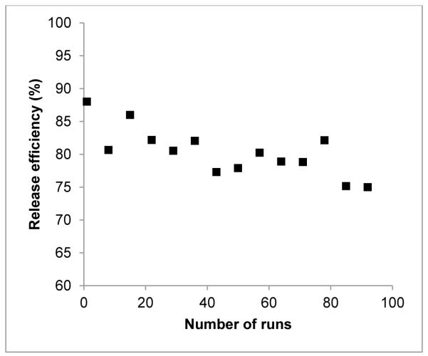
With repeated use, the brass-anode platinum-cathode flow cell exhibits a slight decline in the release efficiency (Fig. 7). This performance decline could be attributed to a buildup of metallic oxidation visible on both the Pt and brass surfaces and visible erosion of the platinum plating despite the use of a cathodic potential of −2 V during the washing process. Consistent with this hypothesis, sanding the brass surface and re-plating the Pt surface restored the performance.
Figure 7.
With repeated use, there is a gradual decrease in the release efficiency (%) of [18F]fluoride from the electrochemical cell with a brass anode at an applied potential of −2 V, and a flow rate of 1.0 mL/min.
In comparison, when using Ni, Ag and Zn anodes, clogging occurs after approximately 10 trap and release experiments because of extensive oxide formation. For the brass-Pt configuration, relatively reproducible trapping and release was achieved in over 100 experiments with the same electrochemical cell. These results further support the use of brass as the anode material for the electrochemical cell.
Flow through synthesizer and multi-human dose production of [18F]FDG
Using the optimized parameters, as described above, for the trap and release of [18F]fluoride in combination with the flow through synthesizer, we were able to routinely synthesize [18F]FDG with a radiochemical yield of 56±4% (decay corrected, n=4) as shown in Table 1. [18F]Fluoride trap and release efficiencies were 98±2% and 83±3% (n=4), respectively. Through radio-TLC analyses, the fluorination of the mannose triflate to the intermediate [18F]FTAG was 87±3% (n=4) with the remainder being the unreacted [18F]fluoride. Conversion of [18F]FTAG to [18F]FDG was typically 81±3% (n=4) efficient. Without the FDG purification cartridge installed in the system, the final product contained 4% of [18F]fluoride along with 96% of [18F]FDG. This contamination was found to be reduced by the use of purification cartridges downstream of the hydrolysis cartridge. Overall, about 3% of the total synthesized [18F]FTAG was lost, and either remained trapped onto the tC18 hydrolysis cartridge or was washed into the waste. We also demonstrated the production of a multi-human dose (5.92 GBq) of [18F]FDG utilizing this method, a sufficient quantity for several human doses. This reflects the potential of the combined electrochemical trap and release cell and flow synthesizer and its utility in larger-scale adaptations in 18F-radiotracer synthesis.
Table 1.
Production of [18F]FDG under optimized parameters. Performance percentages show an average of 4 runs (decay corrected). Starting activity was typically 925 MBq. A sample calculation is shown in the Supplementary Matererial
| Step | Reagents | Temperature (°C) | Time (min) | Performance |
|---|---|---|---|---|
| Trap [18F]fluoride | Aqueous [18F]fluoride |
65 | 0.5 | 98±2% trapped |
| Flush residual water | MeCN then Argon | 65 | 0.5 | 98±2% retained |
| Release [18F]fluoride | Release solution (K-222, K2CO3 in MeCN) |
65 | 3.5 | 83±3% released |
| Fluorination reaction | Released [18F]fluoride and mannose triflate |
110 | 4.5 | 87±3% conversion |
|
C18 cartridge base
hydrolysis and FDG purification cartridge (Total) |
Diluted [18F]FTAG then NaOH and water |
20 | 5 | 81±3% conversion |
| 14 | 56±4% yield |
X-ray photoelectron spectroscopy (XPS) studies
XPS studies helped reveal different mechanisms of fluoride adsorption and release and correlate them to the performance of different anode materials. Due to the poor adsorption performance, Havar and tantalum were not analyzed by XPS. Although copper and silver could not be used as anode materials for the flow cell, XPS analysis were still conducted as it allowed informative comparisons to other metals.
Studies with zinc (Zn) showed chemical shifts in the Zn 2p peaks (as evident by the double peaks) in addition to an increase in the binding energies (Fig. 8 and Table 2). The relative concentration of the shifted peak was larger than the relative percentage of oxygen on the surface which can suggest the possibility of a fluoride-zinc bond. This would explain the lack of success in desorption of fluoride from the Zn electrode during radiochemical experiments. Further analysis of the depth of intercalation of the fluoride ions inside the metal electrode revealed no significant change in the atomic concentrations up to a depth of approximately 500 Å (600 sec of ion milling) from the surface (Fig. 9 and Table 2). If fluoride was adsorbed only at the surface, a marked decrease of the F 1s peak intensity was to be expected at greater depths. The relatively high depth of intercalation could explain the observed poor desorption of fluoride.
Figure 8.
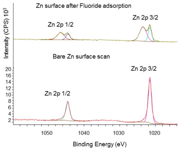
XPS comparison of a bare Zn surface versus a Zn surface after [19F]fluoride adsorption. Chemical shift in Zn 2p suggests a surface bond formation with [19F]fluoride.
Table 2.
Surface elemental composition before and after ion milling of the Zn electrode. There is no observable change in the relative concentrations of F, O or Zn with increased depth. Bare surface is added as a control.
| Zn electrode with adsorbed fluoride | Zn bare surface | ||
|---|---|---|---|
| Etch time (sec) | 0 % Conc. |
600 % Conc. |
0 % Conc. |
| F 1s | 27 | 26 | 0 |
| O 1s | 9 | 9 | 5 |
| Zn 2p 3/2 -shift | 22 | 21 | 0 |
| Zn 2p 3/2 | 11 | 12 | 49 |
| Zn 2p 1/2 - shift | 20 | 23 | 0 |
| Zn 2p 1/2 | 11 | 9 | 46 |
Figure 9.
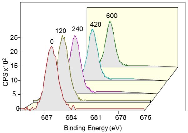
Depth profile analysis of fluoride adsorbed on Zn anode electrode based on the F 1s peak after 0, 120, 240, 360, 420 and 600 sec of ion milling (time indicated above each peak).
On the other hand, copper (Cu) did not show a significant shift in the Cu 2p peak. However, the heavy presence oxides deep in the metal may account for the difficulty in releasing the adsorbed fluoride as the oxide might have hindered its release (Fig. 10 and Table 3). This supports the prediction that fluoride has a high affinity to metal oxides (Piasecki et al., 2010). Furthermore, the adsorption of halides on metal electrodes has been shown to be a complex chemical interaction phenomenon (Spatar’ and Vataman, 1991) and the presence of an energy shifted oxygen peak deep in the copper electrode could be suggestive of a chemical complex formation with fluoride. Together, these findings (heavy presence of oxides and deep intercalation of fluoride into the metal) support the experimentally observed phenomena of fluoride readily adsorbing onto Cu, but poor desorption.
Figure 10.
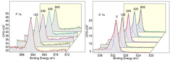
Depth profiling of fluoride adsorbed on Cu anode by ion milling from 0 to 600 sec with the duration of ion milling (sec) indicated above spectra. Analysis of F 1s (left) and O 1s (right) peaks show the heavy presence of fluoride and oxide (up to 500 Å) in the Cu anode.
Table 3.
Elemental compositions before and after 600 sec (~500 Å) of ion milling of Cu (left) and Ag (right) surfaces with adsorbed fluoride. Presence of oxide is observed. Cu electrode shows little decrease in adsorbed fluoride after 600 sec of ion milling. Only trace amounts of fluoride are adsorbed on to the Ag electrode.
| Cu electrode with adsorbed fluoride | Ag electrode with adsorbed fluoride | ||||
|---|---|---|---|---|---|
| Etch time: | 0 sec % Conc. |
600 sec % Conc. |
Etch time: | 0 sec % Conc. |
600 sec % Conc. |
| F 1s | 14 | 12 | F 1s | 1 | 0 |
| O 1s | 33 | 27 | O 1s | 34 | 33 |
| Cu 2p | 53 | 61 | Ag 3d | 65 | 67 |
Similar to the Cu anode, the silver (Ag) anode showed significant oxide formation (Table 2) which does not decrease even after 10 min (~500 Å) of ion milling. Less than 1% fluoride was detected on the surface. Depending on the interaction between fluoride and silver, the high solubility of AgF in water and MeCN might be another contributing factor to the electrode’s inability to retain the fluoride ions during the electrochemical process and the subsequent MeCN wash. The evidence of highly oxidized surfaces of Cu and Ag supports the observed effects of clogging in the microfluidic channels, which prevented the performance evaluation of these surfaces as the anode in the electrochemical cell.
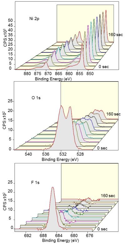
The good adsorption and release performance of the nickel (Ni) electrode during radiochemical experiments (Fig. 3) are supported by XPS surface analysis. The most revealing characteristic of Ni, as shown in Fig. 11 and Table 4, is the high percentage concentration of fluoride on the surface that decreases quickly upon ion milling; in particular, the relative percentage concentration of fluoride decreases to 0% after ion milling of only 160 sec. In addition to the decrease in fluoride, there was a decrease in the presence of oxide from 39% to 12% after etching for 160 sec. These data suggest that the fluoride is trapped at or near the surface.
Figure 11.
XPS depth profiling of Ni anode with adsorbed fluoride by ion milling from 0 to 160 sec in 20 sec increments (front to back) showing Ni 2p (top), O 1s (middle), and F 1s (bottom) peaks. The composition % of Ni substrate increases as the surface is cleaned via ion etching. XPS spectra of O 1s and F1s suggest that fluoride and oxides are much more confined to the surface in comparison to that of Cu and Zn.
Table 4.
Elemental composition of Ni (left) and Au (right) at 0 and 160 sec of ion milling. For both Ni and Au, the oxide and adsorbed fluoride are confined to the surface.
| Ni electrode with adsorbed fluoride | Au electrode with adsorbed fluoride | ||||
|---|---|---|---|---|---|
| Etch time: | 0 sec % Conc. |
160 sec % Conc. |
Etch time: | 0 sec % Conc. |
160 sec % Conc. |
| F 1s | 14 | 0 | F 1s | 4 | 0 |
| O 1s | 39 | 12 | O 1s | 25 | 12 |
| Ni 2p | 47 | 88 | Au 4f | 71 | 88 |
The analysis of the gold (Au) foil anode with adsorbed fluoride shows the presence of very little fluoride on the surface which also quickly decreases upon etching with the ion gun. This is consistent with the difficulty of adsorbing and the ease of release of [18F]fluoride while gold was used as the anode in the electrochemical cell.
Overall, these results have revealed relationships and trends between the ability of the anode to adsorb and release [18F]fluoride to the type of material used. Firstly, if fluoride is able to permeate deep into the material then the release is generally poor. Secondly, the presence of metal-oxides appears to hinder fluoride release and favor fluoride adsorption. Lastly, chemical shifts in materials such as Zn can suggest metal-fluoride interaction which may hinder fluoride desorption. This brief study sheds light on to the mechanism of adsorption and release of fluoride, aids in optimization, and explains the performance of the device with different metals. As mentioned previously, brass was chosen as the anode material because it has a slightly greater combined trap and release efficiency compared to that of Ni. From these studies we hypothesize that a metal with desirable trapping and release characteristics would exhibit surface only formation of metal oxides accompanied with shallow trapping of fluoride and a lack of direct metal-halide bonds.
Conclusions
Reliable trap and release of [18F]fluoride with corresponding efficiencies of 95±4% (n=7) and 88±3% (n=7) were achieved in a simple and reusable electrochemical micro-flow cell with a brass anode and a platinum-plated cathode. Through the optimization of various trap and release parameters, the process of trapping [18F]fluoride from 1 mL of proton irradiated [18O]water and release into a solution of K-222 and K2CO3 in MeCN can be easily completed in under 4.5 min. In comparison to previous studies this represents an improvement in the efficiency and overall time required for the trap and release of [18F]fluoride from water into an organic solution. By interfacing the electrochemical flow cell to a custom-built flow-through synthesis apparatus, [18F]FDG was synthesized in 56±4% in less than 15 min. The use of a flow-through reactor eliminates the process of redissolving evaporatively-dried [18F]fluoride and moving it from one container to another, which can cause noticeable radioactivity losses, especially when very small volumes are involved. By substituting azeotropic distillation with electrochemical separation of [18F]fluoride from [18O]water in a reliable and efficient manner, miniaturized flow reactors can be made that are smaller, and simpler than those of traditional approaches to radiotracer synthesis.
Empirically, it was observed that the performance of the device depends strongly on the particular choice of metal. By performing XPS studies on different anode surfaces after fluoride trapping, we hypothesize that the performance of fluoride adsorption and desorption is related to surface oxides, depth of intercalation, and the nature of chemical bonds formed on the surface during the electrochemical process. We anticipate this knowledge will lead to further optimizations of electrochemical trapping cells and high-speed synthesis of diverse 18F-labled radiotracers.
Supplementary Material
Acknowledgements
We thank Dr. Nagichettiar Satymurthy for his many helpful suggestions regarding the system, experimental designs, and manuscript, and for supplying electrode materials. We also greatly appreciate the electronic design and instrument fabrication help of Mr. Robert W. Silverman, the valuable suggestions from Dr. Pei Yuin Keng, and the prototyping assistance of Mr. Dirk Williams and Mr. Darin Williams. This work was funded in part by the University of California Cancer Research Coordinating Committee, the Department of Energy Office of Biological and Environmental Research (DE-SC0001249), and the National Cancer Institute (U54CA151819).
References
- Alexoff D, Schlyer DJ, Wolf AP. Recovery of [18F]fluoride from [18O]water in an electrochemical cell. International Journal of Radiation Applications and Instrumentation. Part A. Applied Radiation and Isotopes. 1989;40:1–6. doi: 10.1016/0883-2889(89)90165-2. [DOI] [PubMed] [Google Scholar]
- Bejot R, Elizarov AM, Ball E, Zhang J, Miraghaie R, Kolb HC, Gouverneur V. Batch-mode microfluidic radiosynthesis of N-succinimidyl-4-[18F]fluorobenzoate for protein labelling. J Label Compd Radiopharm. 2011;54:117–122. [Google Scholar]
- Berridge MS, Apana SM, Hersh JM. Teflon radiolysis as the major source of carrier in fluorine-18. Journal of Labelled Compounds and Radiopharmaceuticals. 2009;52:543–548. [Google Scholar]
- Brivio M, Verboom W, Reinhoudt DN. Miniaturized continuous flow reaction vessels: influence on chemical reactions. Lab Chip. 2006;6:329–344. doi: 10.1039/b510856j. [DOI] [PubMed] [Google Scholar]
- Elizarov AM, Van Dam RM, Shin YS, Kolb HC, Padgett HC, Stout D, Shu J, Huang J, Daridon A, Heath JR. Design and Optimization of Coin-Shaped Microreactor Chips for PET Radiopharmaceutical Synthesis. J Nucl Med. 2010;51:282–287. doi: 10.2967/jnumed.109.065946. [DOI] [PMC free article] [PubMed] [Google Scholar]
- Endo O, Kiguchi M, Yokoyama T, Ito M, Ohta T. In-situ X-ray absorption studies of bromine on the Ag(100) electrode. Journal of Electroanalytical Chemistry. 1999;473:19–24. [Google Scholar]
- Gillies JM, Prenant C, Chimon GN, Smethurst GJ, Perrie W, Hamblett I, Dekker B, Zweit J. Microfluidic reactor for the radiosynthesis of PET radiotracers. Applied Radiation and Isotopes. 2006;64:325–332. doi: 10.1016/j.apradiso.2005.08.007. [DOI] [PubMed] [Google Scholar]
- Hamacher K, Coenen HH. No-carrier-added nucleophilic 18F-labelling in an electrochemical cell exemplified by the routine production of [18F]altanserin. Applied Radiation and Isotopes. 2006;64:989–994. doi: 10.1016/j.apradiso.2006.03.005. [DOI] [PubMed] [Google Scholar]
- Hamacher K, Hirschfelder T, Coenen HH. Electrochemical cell for separation of [18F]fluoride from irradiated 18O-water and subsequent no carrier added nucleophilic fluorination. Applied Radiation and Isotopes. 2002;56:519–523. doi: 10.1016/s0969-8043(01)00156-7. [DOI] [PubMed] [Google Scholar]
- Keng PY, Chen S, Ding H, Sadeghi S, Shah GJ, Dooraghi A, Phelps ME, Satyamurthy N, Chatziioannou AF, Kim C-J, Van Dam RM. Micro-chemical synthesis of molecular probes on an electronic microfluidic device. PNAS. 2012;109:690–695. doi: 10.1073/pnas.1117566109. [DOI] [PMC free article] [PubMed] [Google Scholar]
- Lee C-C, Sui G, Elizarov A, Shu CJ, Shin Y-S, Dooley AN, Huang J, Daridon A, Wyatt P, Stout D, Kolb HC, Witte ON, Satyamurthy N, Heath JR, Phelps ME, Quake SR, Tseng H-R. Multistep Synthesis of a Radiolabeled Imaging Probe Using Integrated Microfluidics. Science. 2005;310:1793–1796. doi: 10.1126/science.1118919. [DOI] [PubMed] [Google Scholar]
- Lemaire CF, Aerts JJ, Voccia S, Libert LC, Mercier F, Goblet D, Plenevaux AR, Luxen AJ. Fast Production of Highly Reactive No-Carrier-Added [18F]Fluoride for the Labeling of Radiopharmaceuticals. Angewandte Chemie International Edition. 2010;49:3161–3164. doi: 10.1002/anie.200906341. [DOI] [PubMed] [Google Scholar]
- Palmieri A, Ley SV, Hammond K, Polyzos A, Baxendale IR. A microfluidic flow chemistry platform for organic synthesis: the Hofmann rearrangement. Tetrahedron Letters. 2009;50:3287–3289. [Google Scholar]
- Piasecki W, Zarzycki P, Charmas R. Adsorption of alkali metal cations and halide anions on metal oxides: prediction of Hofmeister series using 1-pK triple layer model. Adsorption. 2010;16:295–303. [Google Scholar]
- Sadeghi S, Ding H, Shah GJ, Chen S, Keng PY, Kim C-J, Van Dam RM. On Chip Droplet Characterization: A Practical, High-Sensitivity Measurement of Droplet Impedance in Digital Microfluidics. Anal. Chem. 2012;84:1915–1923. doi: 10.1021/ac202715f. [DOI] [PubMed] [Google Scholar]
- Sadeghi S, Ly J, Deng Y, Van Dam RM. A robust platinum-based electrochemical micro flow cell for drying of [18F]fluoride for PET tracer synthesis. Proceedings of the Fourteenth International Conference on Miniaturized Systems for Chemistry and Life Sciences. Presented at the MicroTAS 2010; Groningen, The Netherlands. 2010. pp. 318–320. [Google Scholar]
- Saiki H, Iwata R, Nakanishi H, Wong R, Ishikawa Y, Furumoto S, Yamahara R, Sakamoto K, Ozeki E. Electrochemical concentration of no-carrier-added [18F]fluoride from [18O]water in a disposable microfluidic cell for radiosynthesis of 18F-labeled radiopharmaceuticals. Applied Radiation and Isotopes. 2010;68:1703–1708. doi: 10.1016/j.apradiso.2010.02.005. [DOI] [PubMed] [Google Scholar]
- Saito F, Nagashima Y, Goto A, Iwaki M, Takahashi N, Oka T, Inoue T, Hyodo T. Electrochemical transfer of 18F from 18O water to aprotic polar solvent. Applied Radiation and Isotopes. 2007;65:524–527. doi: 10.1016/j.apradiso.2007.01.014. [DOI] [PubMed] [Google Scholar]
- Satyamurthy N, Amarasekera B, Alvord CW, Barrio JR, Phelps ME. Tantalum [18O]Water Target for the Production of [18F]Fluoride with High Reactivity for the Preparation of 2-Deoxy-2-[18F]Fluoro-D-Glucose. Molecular Imaging & Biology. 2002;4:65–70. doi: 10.1016/s1095-0397(01)00068-1. [DOI] [PubMed] [Google Scholar]
- Spatar’ FA, Vataman II. Adsorbability of halide ions on metal electrodes. Theoretical and Experimental Chemistry. 1991;26:685–689. [Google Scholar]
- Steel CJ, O’Brien AT, Luthra SK, Brady F. Automated PET radiosyntheses using microfluidic devices. J Label Compd Radiopharm. 2007;50:308–311. [Google Scholar]
- Wester H-J, Schoultz BW, Hultsch C, Henriksen G. Fast and repetitive in-capillary production of [18F]FDG. Eur J Nucl Med Mol Imaging. 2009;36:653–658. doi: 10.1007/s00259-008-0985-9. [DOI] [PubMed] [Google Scholar]
- Wong R, Iwata R, Saiki H, Furumoto S, Ishikawa Y, Ozeki E. Reactivity of electrochemically concentrated anhydrous [18F]fluoride for microfluidic radiosynthesis of 18F-labeled compounds. Applied Radiation and Isotopes. 2012;70:193–199. doi: 10.1016/j.apradiso.2011.09.022. [DOI] [PubMed] [Google Scholar]
- Yamahara R, Nakanishi H, Sakamoto K, Saiki H, Ozeki E, Iwata R. Electrochemical micro-flow-cell for rapid and efficient concentration of [18F]fluoride to aprotic solvent from [18O]water. Presented at the Eleventh International Conference on Miniaturized Systems for Chemistry and Life Sciences; Paris, France. 2007. pp. 856–858. [Google Scholar]
Associated Data
This section collects any data citations, data availability statements, or supplementary materials included in this article.


