Abstract
Detailed spectroscopic and computational studies of the low-spin iron complexes [FeIII(S2Me2N3(Pr,Pr))(N3)] (1) and [FeIII(S2Me2N3(Pr,Pr))]1+ (2) were performed to investigate the unique electronic features of these species and their relation to the low-spin ferric active sites of nitrile hydratases. Low-temperature UV/vis/NIR and MCD spectra of 1 and 2 reflect electronic structures that are dominated by antibonding interactions of the Fe 3d manifold and the equatorial thiolate S 3p orbitals. The six-coordinate complex 1 exhibits a low-energy Sπ → Fe 3dxy (~13000 cm−1) charge-transfer transition that results predominantly from the low energy of the singly occupied Fe 3dxy orbital, due to pure π interactions between this acceptor orbital and both thiolate donor ligands in the equatorial plane. The 3dπ → 3dσ ligand-field transitions in this species occur at higher energies (>15000 cm−1), reflecting its near-octahedral symmetry. The Fe 3dxz,yz → Fe 3dxy (dπ → dπ) transition occurs in the near-IR and probes the FeIII−S π-donor bond; this transition reveals vibronic structure that reflects the strength of this bond (νe ≈ 340 cm−1). In contrast, the ligand-field transitions of the five-coordinate complex 2 are generally at low energy, and the Sπ → Fe charge-transfer transitions occur at much higher energies relative to those in 1. This reflects changes in thiolate bonding in the equatorial plane involving the Fe 3dxy and orbitals. The spectroscopic data lead to a simple bonding model that focuses on the σ and π interactions between the ferric ion and the equatorial thiolate ligands, which depend on the S–Fe–S bond angle in each of the complexes. These electronic descriptions provide insight into the unusual S = ½ ground spin state of these complexes: the orientation of the thiolate ligands in these complexes restricts their π-donor interactions to the equatorial plane and enforces a low-spin state. These anisotropic orbital considerations provide some intriguing insights into the possible electronic interactions at the active site of nitrile hydratases and form the foundation for further studies into these low-spin ferric enzymes.
Introduction
The elucidation of the chemical and physical properties of low-spin non-heme iron systems in biology has received significant attention over recent years as researchers have developed an awareness of their various roles in biological processes. The significance of high-spin non-heme iron species in nature has been long established;1 these sites offer a wide variety of biological activity ranging from electron-transfer sites1–3 (i.e., rubredoxins, ferredoxins, and other iron–sulfur sites) to oxygenases4–8 (e.g., lipoxygenases and protocatechuate dioxygenases). The biological importance of low-spin iron sites has generally focused on the wide range of heme-based active sites involved in electron transfer and catalysis. More recently, the involvement of low-spin non-heme iron systems in biology has led to increased activity, including significant interest in bleomycins9–11 (a class of metal-requiring antibiotics) and nitrile hydratases,12–16 which catalyze the hydrolysis of nitriles to their corresponding amides.
From a coordination chemistry perspective, the active sites of iron-containing nitrile hydratases are of specific interest in that they are low-spin yet contain three strong π-donor thiolate ligands. The strong π-donor interaction is reflected in the presence of an intense low-energy band in the absorption spectrum,17–19 which results from Sπ → Fe(III) charge transfer.20 Ligand-field arguments would suggest that the presence of such strong π-donor ligands should serve to decrease 10Dq in the spectrochemical series and thus stabilize high-spin states. It is thus interesting to consider how a ferric site surrounded by strong π-donor thiolate ligands might exist preferentially in the low-spin S = ½ state. These issues have lead to impressive efforts in designing appropriate synthetic ligand frameworks that exhibit similar behavior.12,14–16,21 More recently, Richards and co-workers have performed a series of DFT-based computational studies on several six-coordinate model systems, providing insight into this question from a theoretical standpoint.22,23 However, spectroscopic approaches have not been used to tackle these issues. Furthermore, debate as to the oxidation state of the three cysteine ligands17,24–26 in the active protein has served to focus efforts on obtaining details of the specific bonding interactions that are responsible for the unusual spin state of the system and its interesting spectroscopic features.
A series of model complexes developed by some of us exhibits some extremely important similarities to the basic ligand framework in the protein.15,27–31 The [N3(Pr,Pr)S2Me2]2− chelating ligand (Figure 1) allows for exogenous ligand binding and provides two thiolate ligands and two strong σ-donating imine ligands that are reasonable substitutes for the two deprotonated amide nitrogen ligands found in the protein. This chelating ligand forms a five-coordinate ferric species (2) that has a low-spin (S = ½) ground state and exists in a spin equilibrium with higher-energy spin states populated at relatively low temperatures (~100 K). Exogenous ligands coordinate the iron, resulting in a six-coordinate species that exhibits striking similarities to the active site of the native nitrile hydratases. For example, the azide-bound six-coordinate species (1) exists in a stable low-spin ground state (even at higher temperatures) and exhibits an intense low-energy transition at 708 nm (ε ≈ 1600 M−1 cm−1).27
Figure 1.
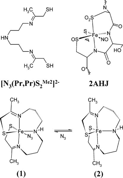
Structural representation of the six-coordinate [FeIII(S2Me2N3(Pr,Pr))(N3)] (1) and five-coordinate [FeIII(S2Me2N3(Pr,Pr))]1+ (2) model complexes investigated in this study. In addition, the chelating ligand structure and that of the active site an NO-bound form of nitrile hydratase are also shown for comparison (obtained from the Protein Data Bank 2AHJ). Protons have been removed for clarity.
To develop a better understanding of the electronic and geometric factors that affect the spectroscopic properties of these low-spin non-heme iron thiolate complexes, we have used a combination of spectroscopic and theoretical methods to elucidate the electronic structure of the six-coordinate azide-bound [FeIII(S2Me2N3(Pr,Pr))(N3)] complex (1) and its parent five-coordinate [FeIII(S2Me2N3(Pr,Pr))]1+ complex (2). Low-temperature absorption (Abs) and magnetic circular dischroism (MCD) spectroscopies are applied to complexes 1 and 2 as examples of structurally well-defined low-spin iron thiolate complexes. Density functional and semiempirical configuration interaction calculations are used to assist in the interpretation of the spectroscopic data and to develop an electronic structure description of the two model complexes. The bonding model that is developed from the combination of spectroscopic and computational data is utilized to obtain physical insight into the properties of these non-heme iron thiolate complexes and in particular the electronic origin of their low-spin nature.
Experimental Section
Synthesis and Preparation of Complexes
The synthesis and purification of complexes 1 and 2 were performed as described previously.27 Solid-state mull samples were prepared under inert N2 atmosphere at ambient temperatures. A few milligrams of each sample were finely ground with a few drops of fluorolube mulling agent until the resulting thin paste was smooth (15–20 min). A small aliquot of the mull was then gently sandwiched between two quartz disks. Samples were kept under N2 atmosphere during sample transfer and were kept below 20 K during data acquisition.
Spectroscopy
Low-temperature absorption (LT-Abs) spectra were measured on a Cary 17 double-beam spectrometer attached to a Janis Super Vari-Temp liquid helium cryostat. Low-temperature near-infrared magnetic circular dichroism (LT-NIR-MCD) spectra (600–2000 nm) were obtained using a Jasco J200-D spectropolarimeter with a liquid-N2-cooled InSb detector. Data acquisition was achieved on this instrument by using routines written within the National Instruments LabVIEW software package. A modified Oxford Instruments SM4000-7T magnet/cryostat was suspended in the beam path. LT-MCD spectra in the visible/UV range (300–800 nm) were obtained using a Jasco J810 spectropolarimeter with an extended S-20 photomultiplier tube; data acquisition on this instrument was achieved using Jasco Spectra Manager software. A modified Oxford Instruments SM4-7T magnet/cryostat was used for temperature and magnetic field control on the J810 instrument.
Depolarization of frozen samples was monitored by measuring the differential CD intensity of a nickel (+)-tartarate solution placed before and after the sample compartment. MCD spectra were corrected for zero-field baseline effects induced by inhomogeneity in the mull by subtracting off the corresponding zero-field scans at each temperature. The directionality of the applied magnetic field was also reversed to ensure that all observed peaks were magnetically induced. All reported LT spectroscopic measurements were performed at T = 5 K unless otherwise stated. VH-MCD data were collected by scanning the field slowly in both directions from 0 T to +7 T to 0 T at fixed frequencies. A slight hysteresis was observed during VH data collection that represented less than 2% of the signal intensity and did not affect the overall VH behavior. Abs and MCD spectra were fit concurrently to the minimum number of Gaussian band shapes required to reproduce the spectral distribution using the program PeakFit (SPSS Science). Saturation magnetization data were normalized to the maximum observed intensity.
Theoretical Calculations
DFT calculations were performed using the commercially available Amsterdam Density Functional (ADF1999 and ADF2000) code.32–36 For such calculations, the Vosko, Wilk, and Nusair (VWN) local density approximation37 was supplemented with standard nonlocal corrections from Becke38 and Perdew39,40 (BP86). All ADF results were obtained using a triple-ζ STO basis set (Basis IV) for the valence levels of all heavy atoms. For geometry optimizations, frozen core levels were used such that only the n valence shell was varied. Single-point calculations at the optimized geometries were performed using all-electron basis sets. Excitation energies were obtained by converging the appropriate excited electronic configurations and determining the total energy difference between the excited state and ground state (ΔSCF procedure). Note that several excited configurations could not be appropriately converged and have thus not been reported. All calculations were performed on either an SGI Origin 2000 8-CPU R10k server running IRIX 6.5.3 or an Intel dual Pentium III Xeon system running RedHat Linux 7.0. Parallelization of ADF was implemented using built-in PVM and shared-memory architectures. Details of specific input parameters used for all published calculations are provided as Supporting Information.
All semiempirical calculations reported were of the valence-only type and carried out with the program ORCA, v2.0.41 The INDO/S model was used together with the valence shell ionization potentials and Slater–Condon parameters using standard interaction parameters.42–44 Standard semiempirical parameters were used for this study. Restricted open-shell (ROHF) self-consistent field (SCF) calculations were converged for the S = ½ ground state throughout. The ROHF configuration served as the reference state for a Rumer diagram configuration interaction (CI) calculation that included selected single and double excitations. The initial matrix of CI states was chosen to include all valence excitations to the empty metal 3d orbitals and empty π orbitals in the ligand manifold. All configuration state functions (CSFs) with zeroth-order energy within 50000 cm−1 of the zeroth-order ground state were initially included in the CI matrix; CSFs with interaction energies of <50 cm−1 with the initially selected configurations were removed from the variational calculation. These weakly interacting CSFs were included through second-order perturbation theory after variational convergence. Details of specific input parameters used for these ROHF–CISD calculations are provided as Supporting Information.
Results
Spectroscopy of Complex 1
The low-temperature (LT) mull absorption and magnetic circular dichroism spectra of the six-coordinate azide-bound complex 1 are given in Figure 2. The major features of the mull absorption data (black) correspond well with LT-Abs data for this complex in acetonitrile (blue).45 The Abs/MCD data for the mull were concurrently fit to the minimum number of Gaussian peaks required to reproduce experimentally observed features.46 Results of these fits are shown in Figure 2 and listed in Table 1. The MCD data yield a surprising result in the near-infrared (NIR) region, where a series of low-energy features are observable in the range ~4500–6000 cm−1. The experimental cutoff of the NIR-MCD instrument does not allow complete resolution at lower energies, but the observable features appear at regular intervals of ~340 cm−1, suggesting a vibronic progression on a single electronic transition. In the visible region, two high-intensity bands are observed in absorption centered at about 13000 cm−1 (peak 4) and 21000 cm−1 (peak 9). The high intensity of these bands in absorption suggests that they must contain significant charge-transfer (CT) character. A series of much weaker absorption bands spanning a large energy range (15000–30000 cm−1) show significant MCD intensity and should thus correspond to ligand-field (LF, Fe 3d → 3d) transitions.
Figure 2.
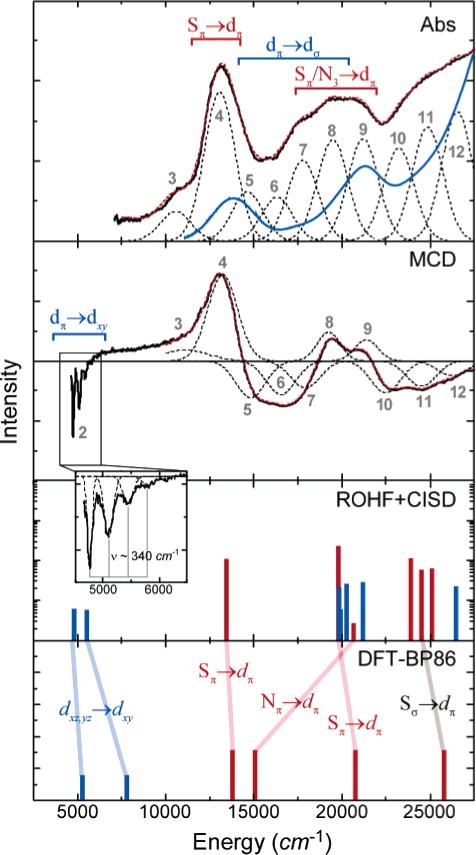
Low-temperature (5 K) spectroscopic data and computational results for six-coordinate model 1. Experimental Abs data are shown for the solid-state mull (black) and acetonitrile solution (blue). The LT-MCD data are shown only for the mull. Fits to the data (red dashed lines) were performed as described in the text; each of the Gaussian peaks in the fit is shown as black dashes. The experimental MCD data are combined data from independent near-IR and UV/vis experiments (grey dashed line indicates cutoff between the two spectra). For the ROHF–CISD and DFT calculations, ligand-field states are shown in black, and charge-transfer states are shown in red. Transition intensities have not been calculated from DFT calculations. Details of the computational methods are given in the Supporting Information (S2). The expanded-scale inset shows vibrational structure on the lowest-energy ligand-field excited state.
Table 1.
Detailed Results for Experimental Concurrent Fits to the Abs and MCD Spectroscopic Data and ROHF-CISD and DFT Calculations on Complex 1a–c
| DFT
|
ROHF–CISD
|
||||||||
|---|---|---|---|---|---|---|---|---|---|
| Abs | MCD | ΔE | ψi → ψf | ΔE | ψi → ψf | fosc | |||
| 1 | – | <5000 | 5300 | 3dxz,yz → 3dxy | 4800 | 3dxz,yz → 3dxy | 14 | ||
| 2 | – | ~5000 | 7800 | 5520 | 13 | ||||
| 3 | 11120 | 10580 | |||||||
| 4 | 13230 | 13070 | 12900 | Sπ → 3dxy | 13430 | Sπ → 3dxy | 534 | ||
| 5 | 14830 | 14650 | 15100 | N3 → 3dxy | |||||
| 6 | 16540 | 16300 | 19810 | Sπ → 3dxy | 1393 | ||||
| 7 | 17930 | 17780 | 19830 | 3d → 3d | 66 | ||||
| 8 | 19640 | 19480 | 20280 | 88 | |||||
| 9 | 21020 | 21220 | 21300 | Sπ → 3dxy | 21180 | N3 → 3dxy | 99 | ||
| 10 | 22500 | 23240 | 23980 |
|
559 | ||||
| 11 | 24520 | 24880 | 24570 | 243 | |||||
| 12 | 26280 | 26560 | 26100 |
|
25120 |
|
260 | ||
| 13 | 28970 | 28310 | |||||||
| 14 | 32140 | 30010 | 29800 |
|
27500 |
|
4182 | ||
| 15 | 33760 | 31740 | 29460 | 523 | |||||
Calculated excited-state energies were obtained from calculations using crystallographic coordinates.
Experimental (Abs, MCD) and Calculated (ΔE for DFT49 and ROHF–CISD) transition energies are given in wavenumbers. Calculated oscillator strengths (fosc) are given in 105.
The correlation between the experimental bands and calculated transitions is complex in this case; see Figure 2 for details.
MCD data were collected over a large range of magnetic fields (0–7 T) to determine the saturation magnetization behavior of 1. The behavior is similar for each of the discernible bands in the MCD spectrum; the data fit very well to a spin-only S = ½ system with g ≈ 2 (see Figure S1), which confirms the low-spin (S = ½) character of the ferric 3d5 species and is consistent with EPR results.15 However, the UV/vis and MCD spectra contrast sharply with the spectra obtained previously for ferric bleomycin (FeIII-BLM), also a low-spin ferric species. In both cases, a very low-energy LF transition is observed in the NIR range, but higher-energy LF features occur at much higher energies (>17000 cm−1) with FeIII-BLM. This difference indicates a substantial difference in the LF 3dπ → 3dσ transitions in 1 relative to FeIII-BLM, which reflects a decreased octahedral splitting (10Dq) in 1. Additionally, the intense low-energy charge-transfer feature in 1 (13250 cm−1) is not present in FeIII-BLM.
Spectroscopy of Complex 2
Comparative data for the five-coordinate model complex 2 are shown in Figure 3, including both low-temperature absorption and MCD spectra. The comparison of mull data to solution data at low temperatures is complicated by binding of solvent to the empty coordination site at low temperatures. At higher temperatures, the mull absorption spectrum is in good agreement with published spectra (Figure S4). Concurrent fits of the mull data using the minimum number of Gaussian peaks yielded good agreement to the experimental data, as shown in Figure 3 (also see Table 2). As for complex 1, the saturation magnetization behavior of this species indicates an S = ½ ground state, although earlier studies27 indicated the presence of a relatively low-lying S = 3/2 state. Our VH-MCD data demonstrate that there is no contribution from this higher spin state in Abs and MCD data obtained below 10 K.
Figure 3.
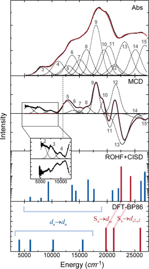
Low-temperature spectroscopic data and computational results for five-coordinate model 2. Experimental data are shown for the solid-state mull. The solution spectrum is not shown, as solvent binds at low temperatures (<150 K) to yield a six-coordinate species and high-temperature spectra are dominated by the high-spin form of 2. Fits to the data (red dashed lines) were performed as described in the text; each of the Gaussian fit peaks is shown (black dashes) and labeled to correspond with Table 2. The experimental MCD data are combined from independent near-IR and UV/vis experiments (grey dashed line indicates cutoff between the two spectra). For the ROHF–CISD and DFT calculations, ligand-field states are shown in black, and charge-transfer states are shown in red. Transition intensities have not been explicitly calculated from DFT calculations. Details of the computational methods are given in the Supporting Information (S3). Expanded-scale inset shows the lowest-energy ligand-field excited states in the 5000–10000 cm−1 region in MCD.
Table 2.
Detailed Results for Experimental Concurrent Fits to the UV/Vis and MCD Spectroscopic Data and ROHF-CISD and DFT49 Calculations on Complex 2a
| DFT
|
ROHF–CISD
|
||||||||
|---|---|---|---|---|---|---|---|---|---|
| Abs | MCD | ΔE | ψi → ψf | ΔE | ψi → ψf | fosc | |||
| 1 | – | – | 4600 |
|
3800 |
|
8 | ||
| 2 | – | 5680 | 5879 | 3dxz → 3dxy | 5800 | 3dxz,yz → 3dxy | 3 | ||
| 3 | 8205 | 7630 | 6600 | 3dxz,yz → 3dxy | 87 | ||||
| 4 | 11045 | 9720 | 10400 |
|
10600 |
|
20 | ||
| 5 | 12825 | 12790 | 11300 | 3d → 3d | 4 | ||||
| 6 | 13635 | 13995 | 13700 | 3d → 3d | 155 | ||||
| 7 | 15075 | 15070 | 15773 |
|
14200 |
|
9 | ||
| 8 | 16285 | 16380 | 17700 | 3d → 3d | 2 | ||||
| 9 | 18070 | 18060 | 19800 | Sπ1 → 3dxy | 18800 | Sπ1 → 3dxy | 714 | ||
| 10 | 19580 | 19290 | 19200 | 3d → 3d | 15 | ||||
| 11 | 20430 | 20560 | 21200 |
|
21400 |
|
1377 | ||
| 12 | 21500 | 21650 | 23800 |
|
3785 | ||||
| 13 | 23395 | 22855 | |||||||
| 14 | 25380 | 25185 | 26100 | Sπ2 → 3dxy | 25300 | Sπ2 → 3dxy | 610 | ||
| 15 | 27110 | 27025 | |||||||
Calculated excited-state energies were obtained from calculations using crystallographic coordinates.
In comparison to 1, complex 2 has a dramatically different excited-state manifold. Several low-lying bands are observed in the 5000–15000 cm−1 range (peaks 3–8); these have relatively strong intensity in MCD, indicating a greater number of low-energy ligand-field transitions. Furthermore, the intense low-energy absorption feature observed in 1 at 13250 cm−1 is at significantly higher energy in 2 (peak 9 at ~18000 cm−1).
Analysis
Geometric Structure of Complex 1
The crystallographic coordinates of 1 were used as a starting geometry for complete geometry optimizations using both semiempirical and density functional calculations. Converged geometries were obtained for both low-spin (S = ½) and high-spin (S = 5/2) states of the six-coordinate species. The DFT-optimized structure is overlaid onto the crystallographic structure in Figure 4; the optimized geometry of 1 in the ground S = ½ spin state is in very good agreement with the reported crystallographically determined structure of the complex, with standard deviations in bond lengths and bond angles involving the central metal ion of 0.03 Å and 2°, respectively. The overall structural motif is preserved because of the rigidity of the chelating ligand, with only small changes in the relative orientation of the two terminal thiolates and the azide ligand. The theoretical S = 5/2 state is over 3 eV higher in energy and involves dramatic elongation of all of the metal–ligand bonds; bond length changes are somewhat limited by the multidentate (S2N3) ligand, but the average bond distance increase is still substantial at ~0.15 Å. The high energy of the S = 5/2 state relative to the ground S = ½ state agrees with the experimentally determined magnetism of this species, which indicates an isolated S = ½ system.
Figure 4.
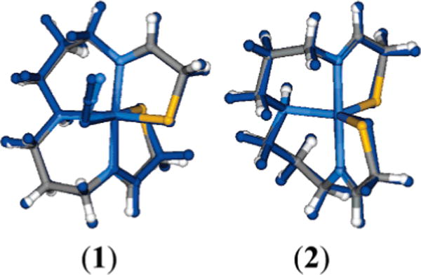
Comparison of the crystallographically defined and DFT-optimized (dark blue) geometries of complexes 1 and 2. See text for details.
The influence of the chelating (S2N3) ligand on the bond distances of the S = ½ system was evaluated by optimizing the geometry of the complex using a truncated ligand set (see S5 in the Supporting Information for more details). The overall geometry of the six-coordinate system remains relatively unchanged. Interestingly, the energy of the S = 5/2 state in this truncated ligand model is much closer in energy to the S = ½ ground state (ΔE ≈ 1 eV) relative to the value calculated for the multidentate chelating (S2N3) ligand. The structural constraints from the chelating ligand thus play some role in stabilizing the low-spin state, but do not completely account for the electronic structure of 1.
Electronic Structure of Complex 1
The ground-state electronic structure of complex 1 was investigated using DFT methods. The overall electronic structure description of 1 is essentially the same for the crystallographic and DFT-optimized structures. These ground-state calculations were complemented with semiempirical ROHF–CISD calculations and excited-state DFT calculations to provide estimates of excited-state energies for comparison with the experimental UV/vis and MCD data.
The general electronic description obtained from these computational studies is that of a distorted octahedral (Oh) complex, as evidenced by the metal 3d orbital splitting shown in Figure 5. An appropriate description requires the spin-unrestricted formalism, which allows the majority spin (spin up, α) and minority spin (spin down, β) to have different energies and orbital descriptions (i.e., one-electron orbitals); the inset in Figure 5 provides a more conventional restricted open-shell (or two-electron) 3d orbital splitting diagram for clarity. The antibonding eg orbitals split because of the strong σ interaction with the imine ligands along the z axis. The major feature of the ground state, however, is the pronounced effect of π bonding on the t2g orbitals, specifically as it affects the 3dxy orbital. The β-spin component of this orbital is the singly occupied molecular orbital (SOMO in a spin-restricted model) because of strong π antibonding interactions in the xy plane with the two cis-equatorial thiolate ligands. The azide ligand also contributes somewhat to the antibonding nature of the Fe 3dxy, although its contribution is significantly less than that from the thiolates. A visual representation of the SOMO is given in Figure 6.
Figure 5.
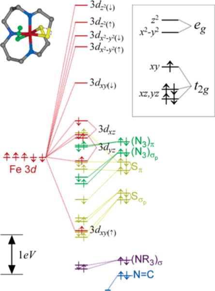
Unrestricted DFT-BP86 ground-state orbital description of 1 using crystallographic coordinates. Results are extremely similar when using the DFT optimized coordinates (given in the Supporting Information). The complete orbital splitting diagram is color-coded according to the major atomic contributors for each of the molecular orbitals. The 3d orbital splitting pattern given in the inset identifies the restricted open-shell picture that best represents the calculated electronic structure (not to scale). See text for details.
Figure 6.
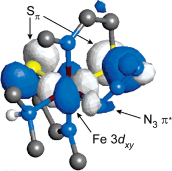
Visual representation of the singly occupied Fe 3dxy orbital in complex 1. The ligands are truncated to facilitate viewing of the orbital surface. The major interactions with the central metal orbital occur with the two equatorial thiolate ligands with more minor interactions with the azide ligand.
The importance of the spin-unrestricted formalism is evidenced by the large splitting of the Fe 3dxy orbital components: the α-spin Fe 3dxy orbital is at a much deeper energy than its β-spin counterpart even though one would generally expect only limited spin polarization of the electronic manifold in a low-spin S = ½ system. As expected, the energy splittings between the α and β spin orbitals of the other 3d orbitals (see Figure 5) are quite small (<0.5 eV), demonstrating that the observed splitting of the α and β 3dxy orbitals (>4 eV) is not simply a spin polarization effect. The large splitting is the result of the high energy of the thiolate Sπ and azide (N3)π orbitals such that they are nearly degenerate with the metal t2g orbitals. The energy matching is such that even the limited spin polarization of the metal 3d orbitals in this low-spin system is enough to drop the metal 3dxy(↑) orbital below the ligand Sπ and (N3)π orbitals. As a result, the Fe 3dxy(↑) becomes bonding with respect to the ligand orbitals and is lowered in energy, yielding an inverted bonding interaction for this particular orbital. The Fe 3dxz,yz orbitals are nonbonding with respect to the high-energy Sπ and (N3)π orbitals so they remain unaffected.
The overall 2–1–2 splitting pattern of the metal 3d orbitals (i.e., ) is also obtained from ROHF-CISD calculations, from which a theoretical UV/vis spectrum has been calculated (Figure 2, bottom). The ground state calculated by ROHF is in good agreement with that obtained from DFT. The single unpaired electron resides in the 3dxy orbital, which is dominated by π interactions from the equatorial thiolate and azide ligands. The calculated spectrum for complex 1 is qualitatively reasonable, but most of the transitions are shifted to higher energy by ~2500 cm−1 compared to the experimental spectra. Overall, however, the calculated spectrum provides further insight into the assignment of the UV/vis and MCD spectra.
The lowest-energy transition, which appears in the near-infrared MCD, is assigned formally as the low-energy 3dπ → 3dπ transition, i.e., from the Fe 3dxz,yz nonbonding orbitals to the Fe 3dxy SOMO. The energy of this transition (peak 2 at ~4500 cm−1) reflects the strength of the Fe–Sπ interactions in the Fe 3dxy orbital. The observed vibronic progression in this band (ν = 340 cm−1; Figure 2 inset) requires that the excited state be significantly displaced from the ground-state equilibrium position. In this case, the antibonding Fe 3dxy SOMO differs substantially from the nonbonding Fe 3dxz,yz orbitals because of the strong π-donor interactions from the thiolate Sπ orbitals, causing elongation of the Fe–S bonds upon excitation. The spacing of the excited-state vibronic progression is reasonable for Fe–S stretching modes.
The onset of the Fe 3dπ → 3dσ transitions occurs at ~16000 cm−1 (~10000 cm−1 above the 3dπ → 3dπ transitions), an indication of the strength of the LF splitting (10Dq). Between these two LF regions, a low-energy ligand-to-metal charge-transfer (LMCT) transition occurs between the Sπ ligand orbitals and the Fe 3dxy SOMO acceptor orbital (peak 4). This general assignment is well supported by the ROHF–CISD results and is confirmed through the relative energies of DFT-calculated excited states: the lowest-energy charge-transfer band (vide infra) is lower in energy than the lowest-energy 3dπ → 3dσ transition (see Figure 2).
As indicated from both ROHF–CISD and DFT results, the intense band at 13250 cm−1 is one of the Sπ → Fe 3dxy charge-transfer transitions. The second Sπ → Fe 3dxy band (from the other thiolate 3pπ orbital) is observed at a significantly higher energy (peak 9 at ~20000 cm−1). This unexpectedly large splitting is directly observed as a ground-state splitting of the two Sπ orbitals by ~8000 cm−1 in our DFT results (Figure 5) and is not the result of differing electronic relaxation in the two final states. The ground-state splitting could result from a number of factors including (i) the differing environments of the two thiolate ligands (one is cis to the azide ligand, whereas the other is trans to that same ligand), (ii) ligand-ligand overlap between the two thiolate ligands, (iii) mixing from the azide ligand π orbitals, and (iv) differential mixing with the Fe 3d orbitals. These issues are considered in more detail in the Discussion section (vide infra). Although the two intense CT bands separated by ~7000 cm−1 in the UV/vis spectra (most easily seen in the solution spectra) are assigned as the two allowed Sπ → Fe 3dxy CT transitions, excited-state calculations do suggest that significant mixing occurs between the higher-energy Sπ → Fe 3dxy LMCT band and at much weaker (N3)π → Fe 3dxy LMCT band (peak 5) at a similar energy (Table 1). Potential contributions to the spectrum from Sπ → Fe 3dσ transitions are calculated to occur at even higher energies (~25000 cm−1 in ROHF–CISD) and will be weak because of poor overlap between the Sπ orbitals and the and orbitals. Alternatively, one would expect significant intensity for the transitions, but these will be a much higher energies (at >30000 cm−1) because of the large Sπ–Sσ splitting (see Figure 5) in addition to the significant splitting between the Fe 3dxy and orbitals.
Geometric Structure of Complex 2
The geometric structure of 2 was investigated by performing full DFT geometry optimizations on the lowest-energy S = ½, S = 3/2, and S = 5/2 electronic states. Comparative results are given in Figure 7. The S = ½ state is lowest in energy, but the S = 3/2 state is calculated to be only ~0.3 eV higher in energy. This is in general agreement with SQUID magnetic susceptibility data on 2,27 which indicate that a low-lying higher spin state becomes populated at reasonably low temperatures. The DFT results somewhat overestimate the energy splitting of the S = ½ and S = 3/2 states. The S = 5/2 state is at even higher energy (~0.9 eV above the ground state). The bond distances to the central metal ion increase substantially on going from the low-spin to the high-spin state, as shown in Figure 7.
Figure 7.
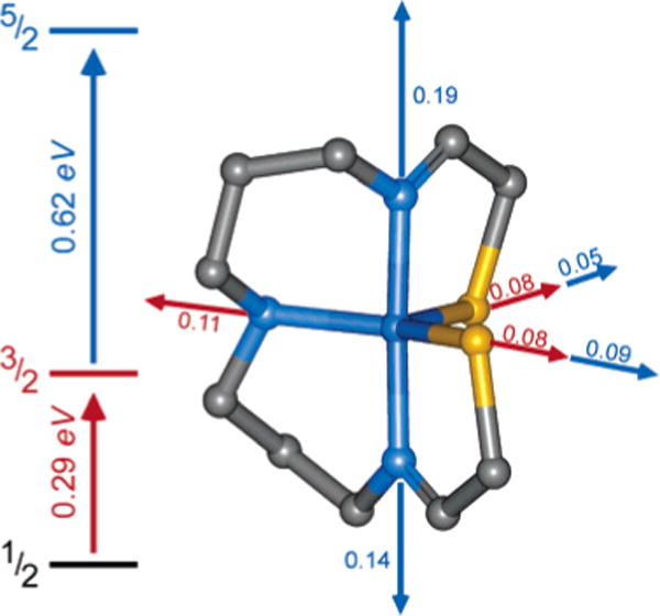
DFT-calculated energetic and geometric changes in the S = ½, 3/2, and 5/2 spin states of complex 2. Bond distance changes are indicated in ångstroms.
As with complex 1, the overall geometric structure of the S = ½ ground state of 2 changes little during the geometry optimization process. The DFT-calculated geometry is very consistent with the crystallographically determined geometry for the complex. The iron-thiolate bond distances are slightly elongated (by ~0.03 Å) but the bond distances are still reasonable. The largest discrepancy occurs in the bond angles at the metal site in the equatorial plane; these angles deviate by up to 7° compared to the crystallographic data. The larger deviation is not surprising because of decreased steric crowding in the xy plane upon loss of the azide ligand.
Electronic Structure of Complex 2
The DFT-calculated electronic structure for the S = ½ ground state corresponding to the crystallographic structure of the five-coordinate complex 2 is given graphically in Figure 8. The Fe 3dxz and 3dyz orbitals are lowest in energy, followed by the singly occupied Fe 3dxy orbital. In contrast to six-coordinate 1, the orbital is very close in energy to the SOMO in 2. The highest energy metal-based orbital is the axial σ-anti-bonding (to imine ligands) .
Figure 8.
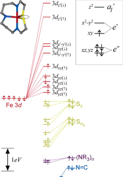
Unrestricted DFT-BP86 ground-state orbital description of 2 using crystallographic coordinates. Results are extremely similar when using the DFT optimized coordinates. The complete orbital splitting diagram is color coded according to the major atomic contributors for each of the molecular orbitals. The 3d orbital splitting pattern given in the inset identifies the restricted open-shell picture that best represents the calculated electronic structure (not to scale). See text for details.
Although the largest contributor to the SOMO is the Fe 3dxy–as in complex 1–the dominant interactions with the ligands are very different from the pure π interactions depicted in Figure 6. The SOMO for complex 2 is shown graphically in Figure 9 and clearly involves mixed π/σ interactions with the two equatorial thiolate ligands. In addition to the strong interactions with the two thiolates, a small contribution from the equatorial amine lone pair (NR3)σ is also present. The orbital is only slightly higher in energy than the SOMO and also involves mixed π/σ interactions with the thiolate ligands (Figure 9, LUMO). The major difference between these two orbitals is the strength of the σ-antibonding contribution from the amine ligand; the orbital points directly toward (NR3)σ and therefore is more destabilized relative to the Fe 3dxy SOMO.
Figure 9.
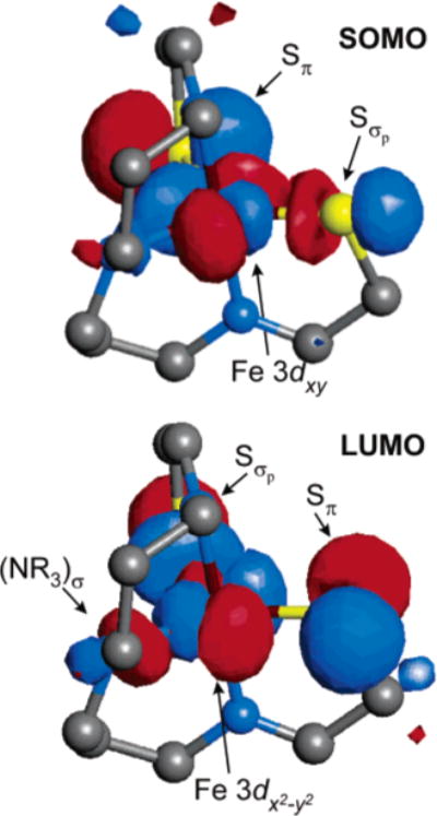
Visual representation of the singly occupied Fe 3dxy orbital (SOMO) and the lowest unoccupied orbital (LUMO) in complex 2. The major contributions to the SOMO and LUMO are indicated.
The overall splitting of the Fe 3d manifold is thus best described as a distorted trigonal bipyramid as shown in the inset of Figure 8. The characteristic 2–2–1 splitting pattern for the metal 3d orbitals (i.e., ) results from the nonbonding character of the lowest two orbitals, mixed π/σ interactions in the equatorial plane for the xy and x2 – y2 orbitals, and strong σ-antibonding interactions along the z axis for the z2 orbital. This splitting pattern is consistent with the experimental Abs/MCD spectra for 2 as shown in Figure 3. Weak transitions occur throughout the low-energy region of the spectrum, corresponding to the relatively low-energy ligand-field transitions. The overall ligand-field manifold is thus significantly lower in energy for 2 (relative to 1) because of a decrease in the energy of the orbital. Concurrently, the Sπ → Fe 3dπ charge-transfer transitions that occurred at very low energy in 1 occur at higher energy for 2 (peak 9 at ~18000 cm−1) because of the greater antibonding character of the Fe 3dxy SOMO that results from mixed σ/π interactions with the equatorial ligands (relative to the π/π interactions in 1 in Figure 6).
ROHF–CISD calculations on complex 2 are consistent with this bonding description (Figure 3, bottom), indicating a manifold of ligand-field transitions at low energy with a concurrent increase in the energy of the charge-transfer transitions (relative to 1) to nearly ~23000 cm−1 (peaks 9–11). As with 1, the ROHF–CISD calculations of these transitions give energies slightly greater than experiment (by ~3000 cm−1; see Table 2); however, the overall spectral distribution is quite reasonable. The results from these semiempirical calculations are further corroborated by the DFT-calculated energies of certain ligand-field and charge-transfer excited states (see Figure 3, bottom).
Discussion
The low-spin non-heme iron complexes (1 and 2) exhibit three unique electronic structural features. First, both species exist as low-spin complexes in their ground electronic state even though they both have two strong π-donor thiolate ligands, which are usually associated with lower 10Dq values. Second, the ligand-field manifold of the five-coordinate species (2) is significantly lower in energy (by ~6000 cm−1) than that of the six-coordinate species (1), which exhibits behavior typical of low-spin ferric species. Third, the lowest-energy charge-transfer band in 1 is ~5000 cm−1 lower in energy than the corresponding transition in 2 even though its coordination number is greater. Each of these three characteristics can be explained using a simple bonding model that derives from the spectroscopy of these two ferric species.
The spectroscopy and electronic structures of both complexes are summarized and correlated in Figure 10. Geometrically, the major change that occurs when azide binds to the five-coordinate complex 2 is a rearrangement of the equatorial plane, which significantly compresses the S–Fe–S angle by nearly 30°. Thus, the most important changes in the electronic structure upon azide-binding occur in the Fe 3dxy and orbitals. The Fe 3dxy orbital decreases in energy on going from 2 ro 1 because its σ-antibonding interaction with one of the thiolate sulfurs is replaced with a π interaction with the same ligand. Conversely, the orbital increases in energy because it gains a new σ* interaction as it loses a weaker π* interaction with one of the equatorial thiolate ligands. This redistribution of the σ*/π* interactions within the xy plane is the basis of the dramatic reorganization of the Fe 3d and CT manifolds observed in Figure 10.
Figure 10.
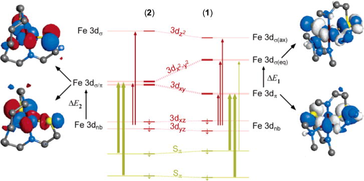
Summary of spectroscopic model used to interpret the observed Abs/MCD spectra and the overall electronic structures of complexes 1 and 2. The orbital splitting is that of the minority spin orbitals for each model complex; the most important spin-allowed transitions are indicated (<25000 cm−1). The orbital description of the 3dxy and orbitals in each complex is also given to emphasize the change in bonding between 2 and 1.
The general electronic structure picture for both complexes provides an explanation for why each of these ferric species has a low-spin ground state. First, the axial imine ligands are extremely strong σ-donor ligands, thus ensuring that the orbital is very high in energy in both 1 and 2. By contrast, the Fe 3dxz,yz orbitals are effectively nonbonding as they are incorrectly oriented to interact with the π-donor thiolate ligands. The orientation of the π-donor ligands is therefore critical in determining the spin state of these complexes. The anisotropic (i.e., in-plane) π-donor character of the thiolate ligands affects the energies of the Fe 3dxy and orbitals, which, contrary to the usual ligand-field description with symmetric ligands, assists in ensuring a low-spin ground state. In the five-coordinate species, both of these orbitals are strongly destabilized (ΔE2 ≈ 10000 cm−1) because of the mixed σ*/π* interactions with the thiolate ligands. This strong destabilization ensures that lowest-energy state is low-spin for this five-coordinate ferric species. The importance of the in-plane (or parallel) orientation of the thiolate π-donor orbitals is further demonstrated by noting that a similar trigonal bipyramidal FeS2N3 complex having perpendicular π-donor contributions from the thiolate ligands exists in a high-spin state and becomes low-spin only upon binding of a sixth exogenous ligand.47
For the six-coordinate complex, the effect of the thiolate π-donor ligands on the Fe 3dπ (t2g in Oh symmetry) orbitals is restricted to the Fe 3dxy orbital, thus mediating their influence on the spin state of this complex; the π-donor contributions are therefore of lesser importance in the six-coordinate species. Additionally, the orbital is strongly destabilized because of two strong σ* interactions with the equatorial thiolates (ΔE1 ≈ 12000 cm−1). Each of these ensures that the preferred spin state is low-spin. A recent DFT study of a series of available six-coordinate model complexes (including 2 from this work) suggests that three-center hyperbonding might play an important role in ensuring a low-spin state for this complex.22 Although this might certainly play a role, the energetics of the Sσ and Sπ contributions (vide infra) to bonding are sufficient to ensure a low-spin ground state without invoking hyperbonding.
The energy splittings ΔE1 and ΔE2 defined in Figure 10 provide a simple way to estimate the energetic contributions from σ and π bonding to the metal center from the thiolate ligands. Because the low-energy ligand-field bands in the five-coordinate complex 2 result directly from the low energy of the orbital through replacement of one Sσ → Fe interaction with a weaker π-donor interaction, we obtain ΔE1 = 2(Eσ − Eπ) and ΔE2 = Eσ + Eπ, where Eσ and Eπ are the energetic contributions from each thiolate ligand to the metal 3d orbitals. From our experimental estimates of ΔE1 and ΔE2, we find that Eσ ≈ 8000 cm−1 and Eπ ≈ 2000 cm−1. The π contributions are therefore relatively important for both the bonding and the spectroscopy in these complexes.
The nature of the intense observable LMCT transitions in the six-coordinate complex is of particular interest when considering these complexes as models for the active site of nitrile hydratases. Two very intense CT bands are observed below 30000 cm−1: the lowest-energy band is at 13000 cm−1 with the higher-lying feature ~7000 cm−1 above that. The spectroscopic assignment indicates that each of these CT bands result from Sπ → 3dπ contributions (formally, one from each of the equatorial thiolate ligands). The higher-lying CT band cannot result from Sπ → 3dσ transitions because they could acquire significant intensity only if the Sπ orbitals were significantly misaligned in the equatorial plane; additionally, the observed splitting between the Fe 3dxy and orbitals is too large (~12000 cm−1). This higher-lying band also cannot result from the azide ligand because similar complexes with spectroscopically silent ligands exhibit very similar spectroscopic features.48,49 The large splitting of the Sπ → 3dπ CT bands results from a large ground-state splitting of the two Sπ orbitals from both ligand–ligand repulsion between the two cis-equatorial thiolates (Figure 5) and the selective π-bonding interactions between the Fe 3dxy orbital and the bonding (lower-energy) combination of the Sπ orbitals (Figure 6).
The spectroscopic features of 2 are similar to those of the photoactivated form of Fe-containing nitrile hydratases; the enzyme itself exhibits two intense CT bands in the visible region at ~14000 cm−1 (ε ≈ 1000 M−1 cm−1) and ~25000 cm−1 (ε ≈ 1000 M−1 cm−1). The low-energy LMCT band in the protein results from the only available reduced cysteine ligand and correlates well with the lowest-energy LMCT band in the model complex. This Sπ → Fe LMCT band is less intense in the enzyme than in 2 (ε ≈ 1600 M−1 cm−1), indicating that the cysteine sulfur is a weaker π donor in the enzyme active site. This is consistent with the greater donor strength of deprotonated amide ligands (relative to the imine ligands in 2), which will decrease the effective charge on the metal center and concomitantly lower the π donor influence of the cysteinate ligand. The higher energy of this LMCT transition is more difficult to evaluate but would also be consistent with a lower effective nuclear charge at the iron. The higher-energy CT band in the protein (which is ~4000 cm−1 higher than that in 2) is likely to result from the singly oxygenated cysteine ligand. Furthermore, the orientation of this ligand in the enzyme (see Figure 1) allows it to participate in an interaction with the Fe center that can maintain an anisotropic π network similar to that in complex 2 (see Chart 1). Oxidation of the cysteine weakens the interaction, resulting in a lowering of the LMCT intensity and a significant increase in its energy because of the less negative effective nuclear charge on the oxidized sulfur. The LMCT intensity is still significant for this transition, supporting the presence of a significant interaction of the RSO-(H) group with the Fe center.
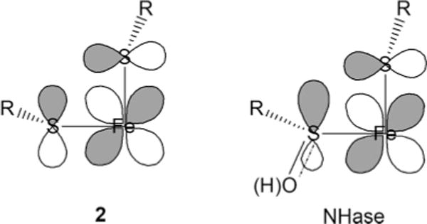
Chart 1
This interpretation of the electronic structure of the active site of nitrile hydratase suggests that the ligands to the iron center are more strongly donating and retain some anisotropic π character provided by two of the cysteine-based ligands. The decreased Lewis acidity of the active site that results from the high donor strength of the ligand set would generally be considered detrimental to the catalytic function of this enzyme, but it might be that specific orbital pathways for charge delocalization over the anisotropic π orbitals of the cysteine and singly oxidized cysteine ligands in Chart 1 (right) are also important in reactivity. Further studies in this area are currently being pursued.
Conclusion
The spectroscopy of these low-spin ferric complexes has provided insights into the factors that govern the electronic structure of low-spin ferric species containing strong anisotropic π-donor ligands such as thiolates. The specific orientation of the π-donor ligands relative to the 3dπ orbitals is crucial in obtaining a low-spin state. Together, the two cis-thiolates in the equatorial plane create a strong donor interaction (π or mixed π/σ) with only one of the three available 3dπ orbitals. This effect defines the nature of the ground state and ensures that the SOMO is the Fe 3dxy orbital and causes a large splitting in the observed Sπ → 3dπ CT bands. As evidenced by the dramatic shift in ligand-field and charge-transfer transitions in the five-coordinate model (2) relative to the six-coordinate species (1), the orientation of the two cis-thiolate ligands with respect to the SOMO is crucial as well. The ~90° S–Fe–S angle in the six-coordinate complex leads to π destabilization of the Fe 3dxy orbital, whereas the larger angle (~120°) in the five-coordinate species results in mixed π/σ destabilization of that orbital. Similar electronic and geometric factors should play an important role in defining the electronic structure of the low-spin ferric active site of nitrile hydratases. This current study provides the basis for detailed investigations of these unique bioinorganic active sites.
Supplementary Material
Acknowledgments
This research is supported by the National Institutes of Health [Grants GM45881 (J.A.K.) and GM40392 (E.I.S.)]. Graduate funding for P.K. was provided in part by Natural Sciences and Engineering Research Council of Canada. F.N. acknowledges a postodoctoral fellowship from the Deutsche Forschungsgemeinschaft (1997–1999).
Footnotes
Supporting Information Available: The following information is available as Supporting Information to this manuscript: (S1) saturation magnetization behavior for complex 1, (S2) computational details for DFT and ROHF–CISD calculations for complex 1, (S3) computational details for DFT and ROHF–CISD calculations for complex 2, (S4) a comparison of the LT-Abs spectra of 1 and 2 in the solid state and in acetonitrile, and (S5) computational details for DFT calculations on a truncated version of 1. This material is available free of charge via the Internet at http://pubs.acs.org.
References
- 1.Holm RH, Kennepohl P, Solomon EI. Chem Rev. 1996;96:2239–2314. doi: 10.1021/cr9500390. [DOI] [PubMed] [Google Scholar]
- 2.Stephens PJ, Jollie DR, Warshel A. Chem Rev. 1996;96:2491–2513. doi: 10.1021/cr950045w. [DOI] [PubMed] [Google Scholar]
- 3.Beinert H. J Biol Inorg Chem. 2000;5:2–15. doi: 10.1007/s007750050002. [DOI] [PubMed] [Google Scholar]
- 4.Costas M, Mehn MP, Jensen MP, Que L. Chem Rev. 2004;104:939–986. doi: 10.1021/cr020628n. [DOI] [PubMed] [Google Scholar]
- 5.Que L, Ho RYN. Chem Rev. 1996;96:2607–2624. doi: 10.1021/cr960039f. [DOI] [PubMed] [Google Scholar]
- 6.Gaffney BJ. Annu Rev Biophys Biomol Struct. 1996;25:431–459. doi: 10.1146/annurev.bb.25.060196.002243. [DOI] [PubMed] [Google Scholar]
- 7.Solomon EI, Brunold TC, Davis MI, Kemsley JN, Lee SK, Lehnert N, Neese F, Skulan AJ, Yang YS, Zhou J. Chem Rev. 2000;100:235–349. doi: 10.1021/cr9900275. [DOI] [PubMed] [Google Scholar]
- 8.Wallar BJ, Lipscomb JD. Chem Rev. 1996;96:2625–2657. doi: 10.1021/cr9500489. [DOI] [PubMed] [Google Scholar]
- 9.Claussen CA, Long EC. Chem Rev. 1999;99:2797–2816. doi: 10.1021/cr980449z. [DOI] [PubMed] [Google Scholar]
- 10.Loeb KE, Zaleski JM, Westre TE, Solomon EI. Abstr Pap Am Chem Soc. 1995;209:593. -INOR. [Google Scholar]
- 11.Neese F, Zaleski JM, Zaleski KL, Solomon EI. J Am Chem Soc. 2000;122:11703–11724. [Google Scholar]
- 12.Artaud I, Chatel S, Chauvin AS, Bonnet D, Kopf MA. Leduc P Coord Chem Rev. 1999;192:577–586. [Google Scholar]
- 13.Endo I, Nojiri M, Tsujimura M, Nakasako M, Nagashima S, Yohda M, Odaka M. J Inorg Biochem. 2001;83:247–253. doi: 10.1016/s0162-0134(00)00171-9. [DOI] [PubMed] [Google Scholar]
- 14.Grapperhaus CA, Patra AK, Poturovic S. J Inorg Biochem. 2001;86:240–240. [Google Scholar]
- 15.Kovacs JA. Chem Rev. 2004;104:825–848. doi: 10.1021/cr020619e. [DOI] [PMC free article] [PubMed] [Google Scholar]
- 16.Mascharak PK. Coord Chem Rev. 2002;225:201–214. [Google Scholar]
- 17.Nelson MJ, Jin HY, Turner IM, Grove G, Scarrow RC, Brennan BA, Que L. J Am Chem Soc. 1991;113:7072–7073. [Google Scholar]
- 18.Sugiura Y, Kuwahara J, Nagasawa T, Yamada H. J Am Chem Soc. 1987;109:5848–5850. [Google Scholar]
- 19.Nagasawa T, Ryuno K, Yamada H. Biochem Biophys Res Commun. 1986;139:1305–1312. doi: 10.1016/s0006-291x(86)80320-5. [DOI] [PubMed] [Google Scholar]
- 20.Brennan BA, Cummings JG, Chase DB, Turner IM, Nelson MJ. Biochemistry. 1996;35:10068–10077. doi: 10.1021/bi960163t. [DOI] [PubMed] [Google Scholar]
- 21.Galardon E, Giorgi M, Artaud I. Chemical Commun. 2004:286–287. doi: 10.1039/b312318a. [DOI] [PubMed] [Google Scholar]
- 22.Chang CH, Boone AJ, Bartlett RJ, Richards NG. J Inorg Chem. 2004;43:458–472. doi: 10.1021/ic0350032. [DOI] [PubMed] [Google Scholar]
- 23.Boone AJ, Chang CH, Greene SN, Herz T, Richards NG. J Coord Chem Rev. 2003;238:291–314. [Google Scholar]
- 24.Kobayashi M, Shimizu S. Nat Biotechnol. 1998;16:733–736. doi: 10.1038/nbt0898-733. [DOI] [PubMed] [Google Scholar]
- 25.Kung I, Schweitzer D, Shearer J, Taylor WD, Jackson HL, Lovell S, Kovacs JA. J Am Chem Soc. 2000;122:8299–8300. [Google Scholar]
- 26.Murakami T, Nojiri M, Nakayama H, Odaka M, Yohda M, Dohmae N, Takio K, Nagamune T, Endo I. J Inorg Biochem. 1999;74:242–242. [Google Scholar]
- 27.Ellison JJ, Nienstedt A, Shoner SC, Barnhart D, Cowen JA, Kovacs JA. J Am Chem Soc. 1998;120:5691–5700. [Google Scholar]
- 28.Schweitzer D, Taylor WD, Kovacs JA. J Inorg Biochem. 1999;74:291–291. [Google Scholar]
- 29.Shearer J, Jackson HL, Schweitzer D, Scarrow RC, Kovacs JA. J Inorg Biochem. 2001;86:428–428. [Google Scholar]
- 30.Shearer J, Jackson HL, Schweitzer D, Rittenberg DK, Leavy TM, Kaminsky W, Scarrow RC, Kovacs JA. J Am Chem Soc. 2002;124:11417–11428. doi: 10.1021/ja012555f. [DOI] [PMC free article] [PubMed] [Google Scholar]
- 31.Shoner SC, Barnhart D, Kovacs JA. Inorg Chem. 1995;34:4517–4518. [Google Scholar]
- 32.Baerends EJ, Ellis DE, Ros P. Chem Phys. 1973;2:41–51. [Google Scholar]
- 33.Versluis L, Ziegler T. J Chem Phys. 1988;88:322–328. [Google Scholar]
- 34.Te Velde G, Bickelhaupt FM, Baerends EJ, Fonseca Guerra C, van Gisbergen SJA, Snijders JG, Ziegler TJ. Comput Chem. 2001;22:931–967. [Google Scholar]
- 35.Te Velde G, Baerends EJ. J Comput Phys. 1992;99:84–98. [Google Scholar]
- 36.Guerra CF, Snijders JG, Te Velde G, Baerends EJ. Theor Chem Acc. 1998;99:391–403. [Google Scholar]
- 37.Vosko SH, Wilk L, Nusair M. Can J Phys. 1980;58:1200–1211. [Google Scholar]
- 38.Becke AD. Phys Rev A: Gen Phys. 1988;38:3098–3100. doi: 10.1103/physreva.38.3098. [DOI] [PubMed] [Google Scholar]
- 39.Perdew JP. Phys Rev B: Condens Matter. 1986;33:8822. doi: 10.1103/physrevb.33.8822. [DOI] [PubMed] [Google Scholar]
- 40.Perdew JP, Burke K, Ernzerhof M. ACS Symp Ser. 1996;629:453–462. [Google Scholar]
- 41.Neese F. ORCA—An ab Initio, Density Functional, and Semiempirical Program Package, V2. Max-Planck-Institut für Bioanorganische Chemie; Mülheim an der Ruhr, Germany: 2000. [Google Scholar]
- 42.Anderson WP, Edwards WD, Zerner MC. Inorg Chem. 1986;25:2728–2732. [Google Scholar]
- 43.Zerner MC, Loew GH, Kirchner RF, Muellerwesterhoff UT. J Am Chem Soc. 1980;102:589–599. [Google Scholar]
- 44.Bacon AD, Zerner MC. Theor Chim Acta. 1979;53:21–54. [Google Scholar]
- 45.The transition intensities obtained from the mull absorption spectrum differ from those obtained in the solution data because of a scattering background that cannot be easily subtracted from the data. For this reason, intensities obtained from the mull absorption are not reliable. The experimental energies of the observed transitions are not significantly affected by the scattering background.
- 46.A minimal bandwidth was also enforced for both Abs (2000 cm−1) and MCD (1000 cm−1) to prevent the formation of broad background features in the spectroscopic fits.
- 47.Noveron JC, Olmstead MM, Mascharak PK. J Am Chem Soc. 2001;123:3247–3259. doi: 10.1021/ja001253v. [DOI] [PubMed] [Google Scholar]
- 48.Kennepohl P, Kovacs JA, Solomon EI. Stanford University, Stanford CA. Unpublished results. [Google Scholar]
- 49.ΔSCF DFT results are given for all final states that converged to an accuracy (1 × 10⁻⁶ H) that was equal to that of the ground-state calculations. All final-state calculations that did not converge to this level have been excluded from this table.
Associated Data
This section collects any data citations, data availability statements, or supplementary materials included in this article.


