Abstract
Cells and tissues in our body are continuously subjected to mechanical stress. Mechanical stimuli, such as tensile and contractile forces, and shear stress, elicit cellular responses, including gene and protein alterations that determine key behaviors, including proliferation, differentiation, migration, and adhesion. Several tools and techniques have been developed to study these mechanobiological phenomena, including micro-electro-mechanical systems (MEMS). MEMS provide a platform for nano-to-microscale mechanical stimulation of biological samples and quantitative analysis of their biomechanical responses. However, current devices are limited in their capability to perform single cell micromechanical stimulations as well as correlating their structural phenotype by imaging techniques simultaneously. In this study, a biocompatible and optically transparent MEMS for single cell mechanobiological studies is reported. A silicon nitride microfabricated device is designed to perform uniaxial tensile deformation of single cells and tissue. Optical transparency and open architecture of the device allows coupling of the MEMS to structural and biophysical assays, including optical microscopy techniques and atomic force microscopy (AFM). We demonstrate the design, fabrication, testing, biocompatibility and multimodal imaging with optical and AFM techniques, providing a proof-of-concept for a multimodal MEMS. The integrated multimodal system would allow simultaneous controlled mechanical stimulation of single cells and correlate cellular response.
KEY TERMS: MICROELECTROMECHANICAL SYSTEMS, MICROFABRICATION, ATOMIC FORCE MICROSCOPY, CELL STRETCHING, MECHANOSENSITIVE ION CHANNELS
INTRODUCTION
Biomechanical forces play an important role in key physiological processes, including embryogenesis,1 wound healing,2 and tumorigenesis.3 Cells interact with the extracellular matrix by sensing exogenous forces or exerting endogenous forces within their surroundings to regulate important cellular responses such as gene expression, proliferation, differentiation, and migration. However, the mechanistic roles of biomechanical forces are not well understood due to limited tools and methods that can simultaneously perform controlled mechanical stimulation and biological characterization at the molecular level. A more detailed understanding of mechanobiology is underway with the development of tools and techniques of modern biotechnology including microfabricated devices termed microelectromechanical systems (MEMS).
MEMS are a class of miniaturized devices fabricated using silicon micromachining techniques to create micro-to-nanoscale mechanical and electrical components to be used as sensors and/or actuators. MEMS sensors, such as microcantilever sensors,4–6 microelectrode and micropost arrays,7–9 are used to measure forces generated by biological systems with high sensitive. Microactuators, such as linear actuators, pressure transducers,10 micropumps and microvalves11, demonstrate controlled mechanical and electrical functions using highly precise actuation systems such as comb drive motors,12–14 voice coil actuators,15 thermoelectric and piezoelectric actuators.16–19 MEMS provide a versatile platform for mechanobiological studies due to their integrated electromechanical capabilities at the micro-to-nanoscale, the length scale at which cells and tissue operate. MEMS sensors and actuators have been successfully used to simulate in vivo biomechanical stimuli in in vitro cell culture.20, 21
At the focus of mechanobiology, tensile stretch is one of the most important biomechanical stimuli for tissue morphogenesis, differentiation, and homeostasis. Cells and tissue are continuously subjected to mechanical stretch during membrane deformation. Several tools and techniques have been designed to apply forces to living cells and tissue. For example, flexible substrates have been used to study mechanical stretching of large cell populations and tissue, but not single cells.22 Techniques used to apply forces to single cells include micropipette aspiration,23 magnetic and optical tweezers,24, 25 and MEMS. MEMS provide the highest accuracy and control over sensing and manipulation within the physiological range of biomechanical forces.20,21,26 MEMS stretching devices, such as comb drive actuators14 and piezoelectric nanoribbons,19 apply tensile deformation to the entire basal membrane of adherent cells, which enable the investigation of cell-matrix interactions. While these devices encompass highly sensitive mechanical capabilities, electrical issues still pertain when operating in liquid and physiological environments such as cell culture.
Furthermore, analysis of the systems provides mostly quantitative measurements of the forces experienced by the cells. Further biological characterization at the cellular and molecular level is limited due to inaccessibility for direct, real-time, and simultaneous observation of cells. Integration of MEMS with optical imaging and complementary investigational modalities would enhance biological applications, but will require a transparent substrate and open interface architecture of the device.
Here we describe the design and fabrication of a biocompatible and optically transparent MEMS, providing a proof-of-concept device for single cell and tissue mechanobiological studies. The silicon nitride microfabricated device employs a mechanical spring platform that can be actuated by an off-chip micromanipulator. Actuation of the device can apply to biological samples a wide range of forces from milli-to-nanoscale, which exceeds the force limitations of existing MEMS devices. Optical transparency of the device allows for simultaneously imaging by optical and fluorescence microscopy in real-time. The open architecture of the device allows for the coupling of other biophysical techniques such as atomic force microscopy (AFM) to monitor changes in structural and biophysical properties. The novelty of this device lies in its inherent versatility with open-ended applications in facilitating the study of mechanobiology.
MATERIALS AND METHODS
Microfabrication process
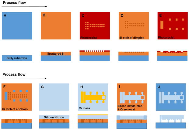
The device was fabricated using silicon-based microfabrication techniques (Fig. 1). To create a fully transparent device, borosilicate glass wafers (Pyrex 7740; Corning, NY) were used as the substrate and a transparent active form of silicon nitride was used to realize the structures of the device. Silicon nitride is known to have favorable material properties that promote biocompatibility.27
Figure 1.
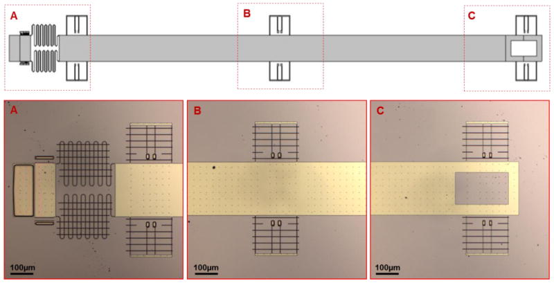
Top view of the whole device showing integral mechanical parts (outlined in red). (A) Testing platform consists of a two-stage (1, 2) suspended platform coupled to a pair of asymmetric springs (3). Stage 1 is the fixed stage and stage 2 is the translatable stage (B) Transmission shaft, intended to extend the length of the device, connects the testing and actuation platform and consists of three pairs of repositioning springs. Maximum displacement is determined by the limit of the repositioning springs (black arrows) (C) Actuation platform can be repositioned by an off-chip micromanipulator.
Prior to fabrication, the wafers were cleaned using Piranha solution (H2SO4: H2O2 = 4:1) to remove all organic contaminants. A 2 μm thick sacrificial layer of amorphous silicon (α-Si) was then deposited onto the wafer using RF-sputtering (Discovery 18, Denton Vacuum, Moorestown, NJ) (Fig. 1B). This sacrificial layer was used to form the mold for the dimples and the anchoring points, which were patterned by photolithography via a Microposit S1813 soda lime mask and the Karl Suss MA6 Mask Aligner (Fig. 1C, E). The mold was then etched away using the Oxford Plasmalab P100 (Oxford Instruments, Frankfurt, Germany) (Fig. 1D, F). The photoresist was removed using acetone and the wafer was deep cleaned with Piranha solution.
A transparent active layer SiNx was subsequently deposited at a thickness of 2 μm by plasma enhanced chemical vapor deposition (PECVD) using the Oxford Plasmalab system (Oxford Instruments, Frankfurt, Germany) (Fig. 1G). This layer which is the active layer of the device, was patterned using a 100 nm evaporated chromium mask (BJD 1800, Temescal, CA) and a liquid chromium etchant solution (H2O, CH3COOH and (NH4)2Ce(NO3)6) (Fig. 1H). Finally, the structures were released in a single layer using dry etching by xenon difluoride (Xetch e1Series™, Xactix, Inc., Pittsburgh, PA), which dissolved all the residual α-Si beneath the devices (Fig. 1I). The dimples on the single layer device prevent static friction during actuation while the anchors fix the suspended silicon nitride structures to the glass substrate at isolated points (Fig. 1J).
Cell culture for device loading
NIH/3T3 mouse embryonic fibroblast cell line was obtained from ATCC and maintained in accordance to their recommended protocol. The cells were cultured in Dulbecco Eagle modified medium (DMEM) (Gibco® Life Technologies, USA) supplemented with 10% fetal bovine serum (FBS, Gibco® Life Technologies, USA) and 1% penicillin-streptomycin (Gibco® Life Technologies, USA) at 37°C and 5% CO2. Upon partial confluency (~70%), the cells were removed from culture and transferred to the devices. First, the cells were rinsed with phosphate buffered saline (PBS, Gibco® Life Technologies, Carlsbad, CA) to remove traces of serum components, then incubated in 0.05% Trypsin-EDTA (1x) (Gibco® Life Technologies, Carlsbad, CA) for 2 to 3 minutes and neutralized in culture medium. The cells were then centrifuged into pellet form and resuspended in fresh culture medium. A small volume (400 μL) of this solution was directly pipetted onto the device, where the cells were allowed to adhere on the platform. Once the cells adhered, more culture medium was added to submerge the devices as they continued to be cultured in 5% CO2 and 37°C. Cells and system were visualized with an Olympus inverted microscope. The system was actuated using a micromanipulator such as the Cell Tram vario-TransferMan NK2 Eppendorf system (Hamburg, Germany).
Fluorescence imaging
Cell viability assay was carried out on the cells to test the biocompatibility of the device. Briefly, the cells were washed free of serum components with PBS, incubated in Calcein AM (Life Technologies) for 30 minutes, and then rinsed with Hank’s balanced salt solution (HBSS). Live cells were distinguished by an intense uniform green fluorescence with excitation wavelengths of ~495 nm and emission of ~515 nm. The green fluorescence results from the hydrolysis of acetoxymethyl (AM) ester by ubiquitous intracellular esterase activity. Cells were imaged in an onstage incubator system (20/20 Technologies, Wilmington, NC) mounted on an Olympus IX71 equipped with FITC filter set (EX/EM: 480/536 nm) (Semrock, Rochester, NY).
Fluo-4 NW calcium assay (Life Technologies) was also carried out on the cells to detect intracellular calcium. Briefly, the culture medium was replaced with the dye loading solution and incubated for 30 minutes at 37°C and then for an additional 30 minutes at room temperature.
AFM imaging
Topographic imaging of cells by atomic force microscopy (AFM) was performed with either MFP-3D BIO (Asylum Research, Santa Barbara, CA) or BioScope SZ AFM (Bruker, Santa Barbara, CA). The MFP-3D BIO is integrated on an Olympus IX51 inverted microscope and the BioScope SZ on an Olympus IX71 (Shinjuku, Tokyo, Japan). Silicon nitride triangular cantilevers with a nominal spring constant of 0.02 N/m were used (TRP400PSA; Asylum Research, Santa Barbara, CA). Live cells were imaged in 2 mL of HBSS diluted in 20 mM of HEPES buffer at room temperature. Height and deflection images were acquired in contact mode scanning over 30 μm × 30 μm to 50 μm × 50 μm regions at scan rates between 0.2 and 0.5 Hz. Fixed cells were subsequently imaged by AFM. To fix the cells, the devices were incubated in 4% paraformaldehyde diluted in PBS for 20 minutes at room temperature and then replenished with PBS. Imaging of fixed cells was carried out with similar AFM scan parameters as live cells.
AFM image analysis was performed using the NanoScope Analysis Version 1.40r51 software (Santa Barbara, CA). Images were processed by low-pass filtering and flattening to remove noise. Simultaneous optical and AFM images were also obtained of the cell-loaded devices using the AFM-inverted microscopes.
RESULTS
Device design and actuation
A two-stage testing platform operated by spring-based actuation system was designed to apply controlled mechanical stretch to a single cell, small cell populations or tissue sections (Fig. 2). The testing platform (250 μm × 200 μm), where samples of tissue and cells are to be placed, consists of a fixed stage anchored to the substrate and, adjacent to it, a suspended stage connected to a pair of asymmetric springs (Fig. 2A). Linear displacement of the suspended stage applies uniaxial tensile stretch to the adherent sample. This actuation is applied at a separate platform, which is connected to the platform-springs via a transmission shaft (Fig. 2B–C). This design of a two-stage platform coupled with spring-based actuation, excluding the transmission shaft, was previously developed.28, 29 The transmission shaft was incorporated here to extend the length of the device for ease of interfacing the device with AFM. The transmission shaft incorporates three pairs of repositioning springs, each fixed by two single anchor points (see Fig. 2) that limit the stretch of the springs. The repositioning springs are also designed to retract by themselves therefore enabling both linear displacement as well as cyclic strain. The device was fabricated using silicon-based microfabrication techniques as outlined in Fig. 1.
Figure 2.
Cross-section of the microfabrication process of the device. (A) The starting substrate is a borosilicate glass substrate (blue). (B) A 2 μm thick α-Si layer (yellow) is deposited via RF sputtering technique. (C – F) The molds for anchors and dimples are formed by photolithography and dry etch. (G) A 2 μm thick layer of SiNx (light blue) is deposited by PECVD. (H) Etching of the structures is realized using 100 nm evaporated chromium patterned with a liquid etchant solution. (I) Etching of SiNx is carried out using reactive ion etching. (J) Xenon difluoride etching is used to dissolve the α-Si layer leaving the structures suspended.
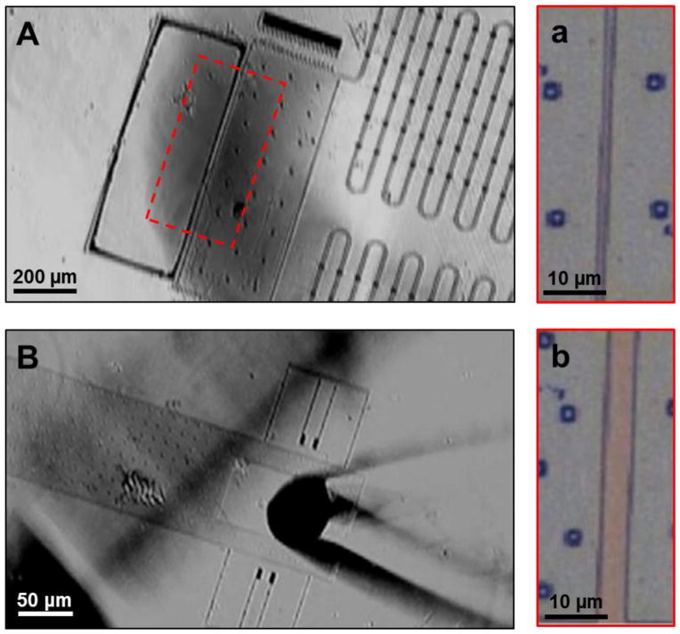
The device is actuated with an off-chip micromanipulator to reposition the actuation platform. A micromanipulator was used to approach the actuation platform using the tip of a pulled glass capillary tube (~50 μm diameter), to mechanically displace it by controlled distances at micron scale. As the device is actuated, the repositioning springs are stretched, which in turn displace the suspended platform thereby applying mechanical stretch to the sample. Cyclic strain can be applied to the sample using a cyclic input (e.g. square wave) from an external manipulator. This proof-of-concept of device actuation was recorded in real-time with optical microscopy at 10x magnification (Fig. 3).
Figure 3.
Time-lapse images of device actuation. (A) Image showing the testing platform at its starting position, which is zoomed in (a). The distance between the fixed stage (1) and the translatable stage (2) is narrow (black arrows). (B) Image (left) showing the actuation platform with a microcapillary tip in action, which is used to mechanically actuate the testing platform. (b) The distance between the fixed and movable stage has widened (black arrows).
Principle of operation
The device can operate as both a sensor and actuator, resolving forces according to Hooke’s law (F = -kx), where the spring constant, ‘k,’ is determined via finite element modeling of the springs (k = 0.0166 N/m) and the displacement, ‘x,’ of the platform is measured.28 The measured displacement is determined by reading a micro-scale reference ruler positioned alongside the suspended stage (Fig. 2A). At its resisting position, the two-stage platform lays 2 μm apart. The maximum displacement of the device is limited by the distance between the edge of the repositioning springs (k = 1.03 N/m) and the anchor point, which is 75 μm (Fig. 2C).28 The device was designed to measure forces between 800 to 1300 nN, which is well within the range of physiological biomechanical responses.26 The accuracy of the measurements taken on this device depends on two main factors: i) the resolution of the microscope objective and ii) the actual thickness of the silicon nitride (2.00 ± 0.01 μm). The predicted tolerance of the device using a 20X objective is within ± 33 nN.
Single cell stretching and contraction
Fibroblast cells were successfully cultured on the device at a low cell density which allowed single cells to attach on the testing platform. A single fibroblast cell was stretched by displacing the testing platform by 2, 6, and 10 μm using a micromanipulator (Fig. 4A–D). By releasing control of the micromanipulator, the cell was allowed to contract as the testing platform returned to its resting position (Fig. 4E). This demonstrates the proof-of-concept of the device for single cell micromanipulation.
Figure 4.

Time-lapse images of single cell stretching and contraction. (A) Image showing the testing platform at its resting position. Inset magnifies the testing platform to show a single cell (outlined in red) attached across the junction of the platform. (B–D) Images showing the testing platform being displaced by 2, 6, and 10 μm using a micromanipulator. Inset magnifies the testing platform to show the single cell (outlined in red) being stretched by the platform. (E) Image showing the testing platform when full released by the micromanipulator allowing the single cell to contract (outlined in red in inset).
Analysis of biocompatibility and optical transparency
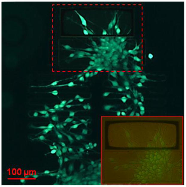
Biocompatibility of the device was demonstrated using fibroblast cells, which are known to be mechanosensitive, expressing stretch-activated ion channels that regulate calcium transients.30 Fibroblast cells were cultured onto the devices and appeared to attach to the surface of the platform with a well-spread morphology similar to that of healthy fibroblast cells plated on a regular petri dish surface. Surface functionalization of the device is not necessary for cell adhesion. There was also no observation of cell death or other significant cytotoxic effects, which was further examined by a fluorescence-based cell viability assay. This showed a uniform distribution of green fluorescence of the cells across the device, shown in Fig. 5, also demonstrating the optical imaging capacity of the transparent device. We conclude that the silicon nitride device is biocompatible and suitable substrate for the fabrication of transparent devices for biomedical and bioimaging applications. Fibroblast cells loaded were also treated with a fluorescence-based calcium assay, Fluo-4 NW, which detected the presence of intracellular calcium simultaneously (Fig. 6).
Figure 5.
Fluorescence images of cell viability assay showing fibroblast cell viability and device compatibility. Inset magnifies the testing platform (outlined in red) by 20X to show individual cells stretched across the platform.
Figure 6.
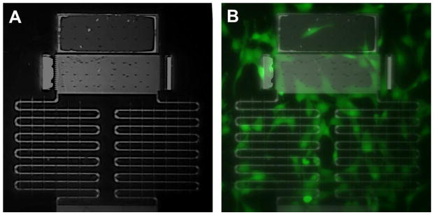
Fluorescence images of calcium assay (Fluo-4) of live fibroblast cells loaded on the device. (A) Image shows the testing platform in detail. (B) Image of fluorescence overlay (taken at a wavelength of 498 nm) showing intracellular calcium in fibroblast cells.
Simultaneous optical and AFM imaging of cell-loaded device
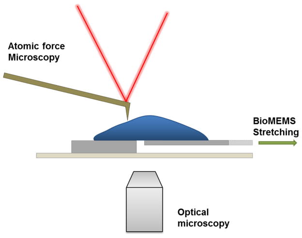
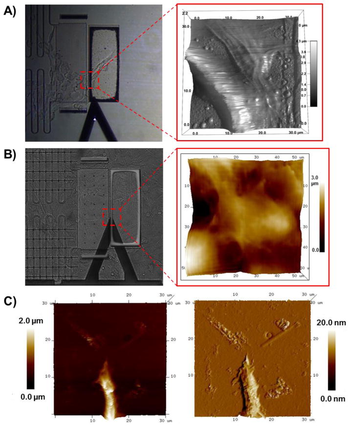
The transparent device was coupled to a multimodal imaging system, incorporating bright field and fluorescence microscopy as well as AFM (Fig. 7). AFM is widely used to study mechanobiology, that when coupled with MEMS, can be used to examine cell morphology and mechanical properties such as elasticity and stiffness.31–39 Herein, live fibroblast cells loaded on the device were imaged by AFM (Fig. 8A–B). AFM imaging of the fixed cells also revealed pronounced cellular features including cell protrusions (Fig. 8C).
Figure 7.
Schematic of the integrated MEMS incorporating optical and AFM imaging. The device can be placed on top of a stage to allow for optical and AFM imaging.
Figure 8.
Phase contrast images (left) of the testing platform showing AFM cantilever approach and the corresponding scan area (outlined in red) of AFM height images (right) of (A) a live fibroblast cell and (B-C) fixed cells.
DISCUSSION
We present the design, fabrication, and testing of a biocompatible, optically transparent and open design device for mechanobiological studies of single cells and tissues. The design of the testing platform enables both force sensing and manipulation at the milli-to-nanoscale, exceeding the force limitations of existing systems (e.g. silicone-based micropost array8–9 and microtissue force gauge,40 microcantilever-based force sensors,4–6,41 comb drive actuators,12,19 and piezoelectric nanoribbons19). In silicone-based microsystems, force measurements are limited by the elastic moduli of the silicone material (1.32–2.97 MPa).42 This range is ideal for measuring forces at a much smaller resolution (e.g. cellular focal adhesions8–9). On the other hand, our device enables force sensitivity of 800 nN to 1500 nN as theoretically determined by finite element modeling that was previously published.28
Herein, device actuation was demonstrated by an off-chip micromanipulator excluding the use of any internal on-chip electrical components to avoid electrical issues that pertain when operating in liquid. By actuating the device, we have shown single cell micromanipulation of stretching and contraction. Future work should develop a cell patterning technique to seed cells only on the testing platform to prevent cells from attaching on other parts of the device. This will improve the functionality of both the sensor and actuation mechanism of the device.
In addition, the biological data supports the biocompatibility of the device, a major hurdle in MEMS and lab-on-chip applications. Optically transparency of the device also presents a novel aspect that contributes to MEMS technology for biological applications. We show that silicon nitride can be microfabricated as a transparent substrate that transmits light for the application of optical imaging techniques. Therefore, in principle the device can be coupled with any fluorescence-based reporter systems to investigate biological characteristics at the molecular level. Moreover, the open interface of the device can be easily coupled with other biophysical techniques. The proof-of-concept MEMS described here can be applied to the study of basic physiological and biological systems as well as defining the underlying mechanisms of pathophysiology and diseases, including signaling pathways and protein activity.
Acknowledgments
The authors thank the staff of the Nano3 facilities at Calit2 at UCSD for the valuable support during the microfabrication process, Dr. Stefano Maggiolino at the University of Trieste for brainstorming. The authors also thank members of Nano-bio-imaging and Devices Laboratory at UCSD, especially Brian Meckes and Srinivasan Ramachandran for their input. F.M. acknowledges her advisor, Dr. Farooq Azam, and support from the Gordon and Betty Moore Foundation MMI initiative. This work was supported by NIH grants R01DA025296 (R.L.) and R01DA024871 (R.L.), and MISE-ICE-CRUI grant 16-06-2010 Project 99 and FVG Region LR 26/2005 Art. 23 (O.S.).
References
- 1.Wozniak MA, Chen CS. Mechanotransduction in development: a growing role for contractility. Nature reviews Molecular cell biology. 2009;10:34–43. doi: 10.1038/nrm2592. [DOI] [PMC free article] [PubMed] [Google Scholar]
- 2.Ingber DE. Mechanobiology and diseases of mechanotransduction. Annals of medicine. 2003;35:564–577. doi: 10.1080/07853890310016333. [DOI] [PubMed] [Google Scholar]
- 3.Huang S, Ingber DE. Cell tension, matrix mechanics, and cancer development. Cancer cell. 2005;8:175–176. doi: 10.1016/j.ccr.2005.08.009. [DOI] [PubMed] [Google Scholar]
- 4.Bashir R, Hilt J, Elibol O, Gupta A, Peppas N. Micromechanical cantilever as an ultrasensitive pH microsensor. Applied Physics Letters. 2002;81:3091–3093. [Google Scholar]
- 5.Gupta A, Akin D, Bashir R. Detection of bacterial cells and antibodies using surface micromachined thin silicon cantilever resonators. Journal of Vacuum Science & Technology B. 2004;22:2785–2791. [Google Scholar]
- 6.Hilt JZ, Gupta AK, Bashir R, Peppas NA. Ultrasensitive biomems sensors based on microcantilevers patterned with environmentally responsive hydrogels. Biomedical Microdevices. 2003;5:177–184. [Google Scholar]
- 7.Yang L, Bashir R. Electrical/electrochemical impedance for rapid detection of foodborne pathogenic bacteria. Biotechnology advances. 2008;26:135–150. doi: 10.1016/j.biotechadv.2007.10.003. [DOI] [PubMed] [Google Scholar]
- 8.Mann JM, Lam RHW, Weng S, Sun Y, Fu J. A silicone-based stretchable micropost array membrane for monitoring live-cell subcellular cytoskeletal response. Lab on a Chip. 12:731–740. doi: 10.1039/c2lc20896b. [DOI] [PMC free article] [PubMed] [Google Scholar]
- 9.Sniadecki NJ, et al. Magnetic microposts as an approach to apply forces to living cells. Proceedings of the National Academy of Sciences. 2007;104:14553–14558. doi: 10.1073/pnas.0611613104. [DOI] [PMC free article] [PubMed] [Google Scholar]
- 10.Kabir A, et al. High sensitivity acoustic transducers with thin p+ membranes and gold back-plate. Sensors and Actuators A: Physical. 1999;78:138–142. [Google Scholar]
- 11.Nguyen N-T, Huang X, Chuan TK. MEMS-micropumps: a review. Journal of Fluids Engineering. 2002;124:384–392. [Google Scholar]
- 12.Jeong K-H, Lee LP. A novel microfabrication of a self-aligned vertical comb drive on a single SOI wafer for optical MEMS applications. Journal of Micromechanics and Microengineering. 2005;15:277. [Google Scholar]
- 13.Milanovic V, Kwon S, Lee LP. Optical MEMs. Conference Digest. 2002 IEEE/LEOS International Conference on 57–58; 2002.IEEE; 2002. [Google Scholar]
- 14.Scuor N, et al. Design of a novel MEMS platform for the biaxial stimulation of living cells. Biomedical microdevices. 2006;8:239–246. doi: 10.1007/s10544-006-8268-3. [DOI] [PubMed] [Google Scholar]
- 15.Pfister BJ, Weihs TP, Betenbaugh M, Bao G. An in vitro uniaxial stretch model for axonal injury. Annals of biomedical engineering. 2003;31:589–598. doi: 10.1114/1.1566445. [DOI] [PubMed] [Google Scholar]
- 16.Chronis N, Lee LP. Micro Electro Mechanical Systems. 17th IEEE International Conference on.(MEMS) 17–20; 2004.IEEE; 2004. [Google Scholar]
- 17.Chronis N, Lee LP. Electrothermally activated SU-8 microgripper for single cell manipulation in solution. Microelectromechanical Systems, Journal of. 2005;14:857–863. [Google Scholar]
- 18.Flynn AM, et al. Piezoelectric micromotors for microrobots. Microelectromechanical Systems, Journal of. 1992;1:44–51. [Google Scholar]
- 19.Nguyen TD, et al. Piezoelectric nanoribbons for monitoring cellular deformations. Nature nanotechnology. 2012;7:587–593. doi: 10.1038/nnano.2012.112. [DOI] [PubMed] [Google Scholar]
- 20.Bashir R. BioMEMS: state-of-the-art in detection, opportunities and prospects. Advanced drug delivery reviews. 2004;56:1565–1586. doi: 10.1016/j.addr.2004.03.002. [DOI] [PubMed] [Google Scholar]
- 21.Kim D-H, Wong PK, Park J, Levchenko A, Sun Y. Microengineered platforms for cell mechanobiology. Annual review of biomedical engineering. 2009;11:203–233. doi: 10.1146/annurev-bioeng-061008-124915. [DOI] [PubMed] [Google Scholar]
- 22.Pelham RJ, Wang Y-L. Cell locomotion and focal adhesions are regulated by substrate flexibility. Proceedings of the National Academy of Sciences. 1997;94:13661–13665. doi: 10.1073/pnas.94.25.13661. [DOI] [PMC free article] [PubMed] [Google Scholar]
- 23.Hochmuth RM. Micropipette aspiration of living cells. Journal of biomechanics. 2000;33:15–22. doi: 10.1016/s0021-9290(99)00175-x. [DOI] [PubMed] [Google Scholar]
- 24.Gosse C, Croquette V. Magnetic tweezers: micromanipulation and force measurement at the molecular level. Biophysical journal. 2002;82:3314–3329. doi: 10.1016/S0006-3495(02)75672-5. [DOI] [PMC free article] [PubMed] [Google Scholar]
- 25.Neuman KC, Nagy A. Single-molecule force spectroscopy: optical tweezers, magnetic tweezers and atomic force microscopy. Nature methods. 2008;5:491. doi: 10.1038/nmeth.1218. [DOI] [PMC free article] [PubMed] [Google Scholar]
- 26.Addae-Mensah KA, Wikswo JP. Measurement techniques for cellular biomechanics in vitro. Exp Biol Med (Maywood) 2008;233:792–809. doi: 10.3181/0710-MR-278. [DOI] [PMC free article] [PubMed] [Google Scholar]
- 27.Neumann A, et al. Comparative investigation of the biocompatibility of various silicon nitride ceramic qualities in vitro. Journal of Materials Science: Materials in Medicine. 2004;15:1135–1140. doi: 10.1023/B:JMSM.0000046396.14073.92. [DOI] [PubMed] [Google Scholar]
- 28.Fior R, Maggiolino S, Lazzarino M, Sbaizero O. SPIE MOEMS-MEMS 792906-792906-6. International Society for Optics and Photonics; 2011. [DOI] [PubMed] [Google Scholar]
- 29.Fior R, Maggiolino S, Lazzarino M, Sbaizero O. A new transparent Bio-MEMS for uni-axial single cell stretching. Microsystem technologies. 2011;17:1581–1587. [Google Scholar]
- 30.Ruder WC, et al. Calcium signaling is gated by a mechanical threshold in three-dimensional. Scientific Reports. 2012;2:1–6. doi: 10.1038/srep00554. [DOI] [PMC free article] [PubMed] [Google Scholar]
- 31.Binnig G, Quate CF, Gerber C. Atomic force microscope. Physical review letters. 1986;56:930. doi: 10.1103/PhysRevLett.56.930. [DOI] [PubMed] [Google Scholar]
- 32.Lal R, John SA. Biological applications of atomic force microscopy. American Journal of Physiology-Cell Physiology. 1994;266:C1–C21. doi: 10.1152/ajpcell.1994.266.1.C1. [DOI] [PubMed] [Google Scholar]
- 33.Shroff SG, Saner DR, Lal R. Dynamic micromechanical properties of cultured rat atrial myocytes measured by atomic force microscopy. American Journal of Physiology-Cell Physiology. 1995;269:C286–C292. doi: 10.1152/ajpcell.1995.269.1.C286. [DOI] [PubMed] [Google Scholar]
- 34.Radmacher M, Fritz M, Kacher CM, Cleveland JP, Hansma PK. Measuring the viscoelastic properties of human platelets with the atomic force microscope. Biophysical Journal. 1996;70:556–567. doi: 10.1016/S0006-3495(96)79602-9. [DOI] [PMC free article] [PubMed] [Google Scholar]
- 35.Almqvist N, et al. Elasticity and adhesion force mapping reveals real-time clustering of growth factor receptors and associated changes in local cellular rheological properties. Biophysical journal. 2004;86:1753–1762. doi: 10.1016/S0006-3495(04)74243-5. [DOI] [PMC free article] [PubMed] [Google Scholar]
- 36.Arce FT, et al. Regulation of the micromechanical properties of pulmonary endothelium by S1P and thrombin: role of cortactin. Biophysical journal. 2008;95:886–894. doi: 10.1529/biophysj.107.127167. [DOI] [PMC free article] [PubMed] [Google Scholar]
- 37.Arce FT, et al. Heterogeneous elastic response of human lung microvascular endothelial cells to barrier modulating stimuli. Nanomedicine: Nanotechnology, Biology and Medicine. 2013;9:875–884. doi: 10.1016/j.nano.2013.03.006. [DOI] [PMC free article] [PubMed] [Google Scholar]
- 38.Luque T, et al. Local micromechanical properties of decellularized lung scaffolds measured with atomic force microscopy. Acta biomaterialia. 2013;9:6852–6859. doi: 10.1016/j.actbio.2013.02.044. [DOI] [PubMed] [Google Scholar]
- 39.MacKay JL, Kumar S. Cell Imaging Techniques. Springer; 2013. pp. 313–329. [Google Scholar]
- 40.Zhao R, Boudou T, Wang WG, Chen CS, Reich DH. Decoupling cell and matrix mechanics in engineered microtissues using magnetically actuated microcantilevers. Advanced Materials. 25:1699–1705. doi: 10.1002/adma.201203585. [DOI] [PMC free article] [PubMed] [Google Scholar]
- 41.Quist A, Chand A, Ramachandran S, Cohen D, Lal R. Piezoresistive cantilever based nanoflow and viscosity sensor for microchannels. Lab on a Chip. 2006;6:1450–1454. doi: 10.1039/b604842k. [DOI] [PubMed] [Google Scholar]
- 42.Johnston ID, McCluskey DK, Tan CKL, Tracey MC. Mechanical characterization of bulk Sylgard 184 for microfluidics and microengineering. Journal of Micromechanics and Microengineering. 24:035017. [Google Scholar]


