Abstract
Flowerlike CeO2 coated with Sr2Fe1.5Mo0.5Ox (Sr-Fe-Mo-oxide) nanoparticles exhibits enhanced conductivity at low temperatures (300–600 oC), e.g. 0.12 S cm−1 at 600 oC, this is comparable to pure ceria (0.1 S cm−1 at 800 oC). Advanced single layer fuel cell was constructed using the flowerlike CeO2/Sr-Fe-Mo-oxide layer attached to a Ni-foam layer coated with the conducting transition metal oxide. Such fuel cell has yielded a peak power density of 802 mWcm−2 at 550 oC. The mechanism of enhanced conductivity and cell performance were analyzed. These results provide a promising strategy for developing advanced low-temperature SOFCs.
Low temperature solid oxide fuel cells (LT-SOFCs) are highly desired as advanced energy conversion and storage devices, in terms of the improvement on issues of mismatch of thermal expansion coefficient of various components and rapid degradation of the components of cells operating at high temperature1,2. Also LT-SOFCs, say below 600 oC, have higher Nernst voltages, which offer a feasible strategy to obtain excellent cell performance3. However, the electrolyte with sufficiently high conductivity and electrocatalyst function are big challenges for development of high performance LT-SOFCs.
Ceria is an important oxygen ion conducting and catalysis material. It has attracted intense attention due to its property to improve the oxygen reduction reaction process through reversely reducing Ce4+ to Ce3+, high oxygen storage capacity as well as good oxide ion conductivity of 10−1 S cm−1 at 800 oC. These properties are comparable to the conductivity of yttrium stabilized zirconia (YSZ) at 1000 oC4,5. Flowerlike textured ceria (F-CeO2) was firstly synthesized and used as an internal catalytic layer for hydrocarbon fueled SOFCs to yield a peak power density of 654 mW cm−2 at operating temperature 600 oC by Sun et al.6,7,8. As reported in the literature, this unique open mesoporous structure has great potential kinetic advantages because of its high surface area and improved dispersion of the active secondary components.
In this work, considering high active surface and large porous surface properties of the flowerlike CeO2, we further modify the surface of F-CeO2 using semiconducting Sr-Fe-Mo-oxide since Sr2Fe1.5Mo0.5Ox (SFM) has high catalytic activity, stable redox property and excellent electrical conductivity9,10,11. The electronic carriers are generated from the mixed coexistence of redox couples Fe2+/Fe3+ and Mo6+/Mo5+, which enhances the ionic conduction due to the introduction of oxygen vacancies into the lattice12,13,14. Liu et al. studied overall electrical properties as regards excellent redox stability9. As reported, the conductivities of SFM reached to 310 S cm−1 and 550 S cm−1 at 780 oC in hydrogen and air atmospheres, respectively1,9. Particularly at low temperatures, SFM also displayed excellent redox stability and high electrical conductivity in both air (8–60 S cm−1) and hydrogen (4–8 S cm−1) environments at 400–600 oC9. These properties indicate that SFM is excellent for both anode and cathode at LT-SOFCS and also at intermediate temperature.
Recently, Dong et al. developed single layer fuel cell (SLFC) using the SFM as one component in a composite with SDC-Na2CO3. They made the SLFC using the 30 wt.% SFM and 70 wt.% SDC-Na2CO3, which exhibits the highest OCV (open circuit voltage) of 1.05 V and output of 360 mW cm−2 at 750 oC1. This also proved that the SFM had good redox electrocatalyst function to make the SLFC work. They also pointed out that to achieve the high performance SLFCs, the electron conductivity (41 S cm−1 in their synthesized SFM) had to be balanced by ions (0.05 S cm−1 level) for their SDC-Na2CO31. In our SLFCs, SFM was mainly utilized as the semiconducting material in F-CeO2/SFM-oxide composite to obtain balanced electronic and ionic conductivities. Through coating electronic conducting SFM on the ionic conducting ceria, we obtained a novel functional semiconductor-ion composite for high performance at low temperature, bellow 600 oC, SLFCs. In recent years, semiconducting and ionic materials have been discovered with the new functionality which can effectively promote the fuel cell redox and ion transport processes at particle levels15,16. This unique property has enabled novel single layer fuel cells (SLFCs) possible, which provides many chances to improve the performance of fuel cells without the limitation of electrolytes17,18. This fuel cell technology was selected as a research breakthrough in SOFCs field, which was named ‘Three in One’ by Nature Nanotechnology19. The SLFCs differ from the conventional three-component configuration of anode/electrolyte/cathode in solid oxide fuel cells in both the technology and science20.
Results
Morphology and structural characterization of F-CeO2 and F-CeO2/Sr-Fe-Mo-oxide composite
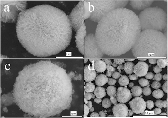
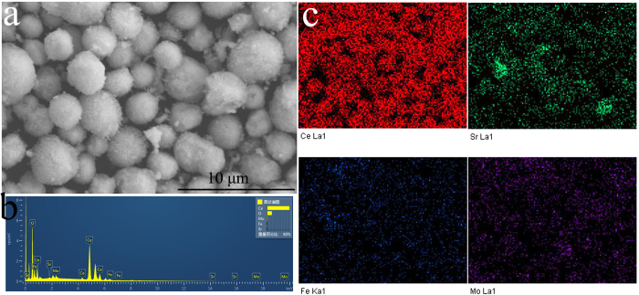
Figure 1 shows the mesoporous ceria microspheres with a flowerlike texture observed by a field-emission scanning electron microscope (FE-SEM). The flowerlike CeO2 particles (see Fig. 1a,b) show an open three-dimensional porous and hollow microsphere composed of numerous interweaved thin flakes as the petals. These microspheres are nearly monodisperse with diameter approximately 2 to 5 μm. Fig.1c,d give an overview of the F-CeO2/Sr-Fe-Mo-oxide composite, which show Sr-Fe-Mo-oxide particles are highly dispersed on the surface of flowerlike CeO2 microspheres without any structural change. These Sr-Fe-Mo-oxide particles were coated on the surface of ceria microsphere. Due to the mesoporous structure of the flowerlike ceria microspheres, it provides sufficient spaces to integrate with sheet-like Sr-Fe-Mo-oxide particles. Sr-Fe-Mo-oxide, as a high electronic conducting material, is coated on the surface of ionic conductor ceria, to make a semiconducting-ionic conducting composite material for the single layer fuel cell. To further analyze the composition of the composite layer, the energy dispersive x-ray (EDX) analysis and elemental mapping of the surrounding flowerlike ceria particles were shown in Fig. 2. The results confirm the existences of Sr, Fe, and Mo, indicating that Sr-Fe-Mo-oxide particles were successfully loaded onto the flowerlike ceria microspheres. It can be seen from the elemental mapping images (Fig. 2c) that various elements of Sr-Fe-Mo-oxide uniformly distributed on the surface of ceria to form F-CeO2/Sr-Fe-Mo-oxide composite type material.
Figure 1. Representative SEM images of.
(a,b) flowerlike CeO2 and (c,d) CeO2 coated with Sr-Fe-Mo-oxide.
Figure 2.
(a) SEM image; (b) EDX and (c) Elemental mapping of the flowerlike ceria coated with Sr-Fe-Mo-oxide after calcination at 750 oC for 2 h.
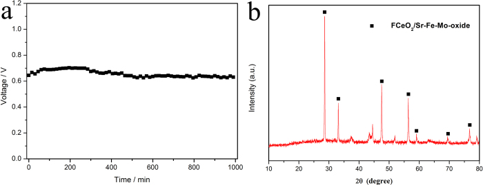
The phases and purity of as-prepared flowerlike ceria and F-CeO2/Sr-Fe-Mo-oxide samples were examined by x-ray diffraction (XRD) patterns. All diffraction peaks in the patterns of Fig. 3a can be ascribed to a face-centered cubic fluorite structure CeO2 (JCPDS 34–0394)21,22. It is worthy noted that all the diffraction peaks of flowerlike CeO2 coated with Sr-Fe-Mo-oxide composite have no shift compared with that of pure ceria. This indicates that the Sr-Fe-Mo-oxide in ceria did not induce any detectable structural changes and doping effect. Hence, our material coating approach is successful. The grain size of F-CeO2 is approximately 6 nm, estimated from the strongest (111) peak with Scherrer equation. Further detailed phase analysis is limited since no peaks of Sr-Fe-Mo-oxide could be detected by XRD. This may be due to the coating limitation at a composition of 4.0 mol% which may be under the XRD detection level. Anyhow, the uniform coating of Sr-Fe-Mo-oxide particles has succeeded in unique F-CeO2/Sr-Fe-Mo-oxide semiconductor-ionic composite material with high electrical and electrocatalyst properties.
Figure 3. XRD patterns of.
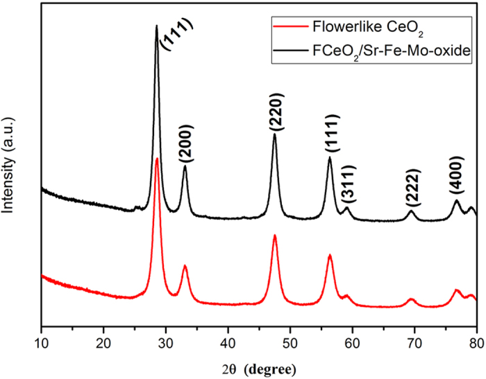
(a) flowerlike CeO2 and (b) CeO2 coated with Sr-Fe-Mo-oxide.
Electrical properties
Figure 4 displays the typical Nyquist plots for a F-CeO2/Sr-Fe-Mo-oxide SLFC obtained by EIS measurements, between 400 and 600 oC. In general, an impedance spectrum of solid state materials exhibits successive semicircles in the complex plane, including the bulk, grain boundary and electrode polarization processes23,24. At low temperatures, e.g. 400 oC and 450 oC, three arcs can be observed. Two located at higher frequency correspond to the grain interior and grain boundary while the start appearing tail in the low frequency is associated with the interface of F-CeO2/Sr-Fe-Mo-oxide and NCAL, i.e. electrode polarization process. The semicircles, representing the grain interior and interface polarization, disappeared with the increase of temperature. The Arrhenius plots obtained from the corresponding Nyquist curves are shown in Fig. 4b.
Figure 4.
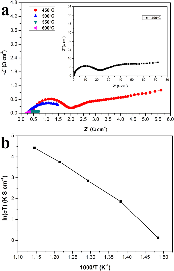
(a) Electrochemical impedance spectra (EIS) at open-circuit voltage (OCV) of fuel cell measured at various temperature from 600 oC to 400 oC upon cooling at an interval of 50 oC and (b) Arrhenius plots corresponding to Nyquist curves using the as-prepared F-CeO2/Sr-Fe-Mo-oxide composite as a single component fuel cell.
Fuel cell performances
Figure 5 shows I-V and I-P characteristics for F-CeO2/Sr-Fe-Mo-oxide fuel cells, measured at the operating temperature of 500 oC, 550 oC and 600 oC, respectively. It shows that all obtained open circuit voltage (OCV) of the fuel cells above 1.0 V at various temperatures, as a prerequisite for obtaining excellent performance, indicating that these as-prepared materials have superior catalytic activity as a single layer material. It can be seen that the maximum current densities were approximately 1718, 2389, and 2574 mA cm−2 at 500 oC, 550 oC and 600 oC, respectively. The peak output power density is 610 mW cm−2 at 500 oC, and increases to 802 mW cm−2 at 550 oC. At 600 oC, a peak power density reaches about 848 mW cm−2, which is consistent with the results of electrical conductivity measured with AC impedance spectrum. These results demonstrate that the conductivity of F-CeO2/Sr-Fe-Mo-oxide composite is sufficiently high. We further evaluated the operation stability of the F-CeO2/Sr-Fe-Mo-oxide fuel cell. The device was operated at a current density of 312.5 mA cm−2 at 530 oC for over 16 h. The voltage change was recorded over time during operation. It can be seen from Fig. 6a that the device has a relatively good durability with the minimal voltage degradation. Generally, the main factor for degradation can be attributed to the increased polarization resistance25. The cell voltage slightly degrades at around 5 h. This could be resulted from the change of cerium valence state in the F-CeO2/Sr-Fe-Mo-oxide composite in the initial stage26,27. Some Ce4+ ions were reduced to Ce3+ ions at H2 input side28,29,30 leading to the coexistence of both cerium ions valence states. The phase analysis of the F-CeO2/Sr-Fe-Mo-oxide layer after long-term stability test was displayed in Fig. 6b. The same peak positions to the F-CeO2/Sr-Fe-Mo-oxide composite can be clearly identified in the XRD patterns. This suggests that the material structure has no changes. Some additional peaks were identified because the NCAL layer was mixed into the material when the sample was scraped from the tested device pellet. Further longer life test is limited by our testing device. After the durability test, we found some rusting surface on the steel chamber of the testing device used, which caused a slight degradation due to the testing device resistance growing with the measurement.
Figure 5. Electrochemical performance of fuel cell based on as-prepared CeO2/SFM-oxide material with a cell configuration:
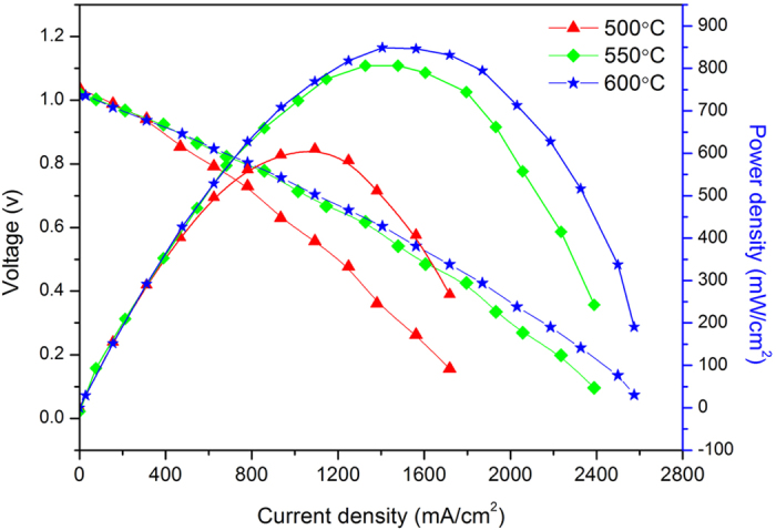
Ni pasted NCAL | F-CeO2/Sr-Fe-Mo-oxide | NCAL pasted on Ni foam measured at various operating temperature of 500 oC, 550 oC and 600 oC.
Figure 6.
(a) The operation stability test result of SLFC at a current density of 312.5 mA/cm2 at 530 oC; b) XRD patterns of F-CeO2/Sr-Fe-Mo-oxide layer after long-term stability test.
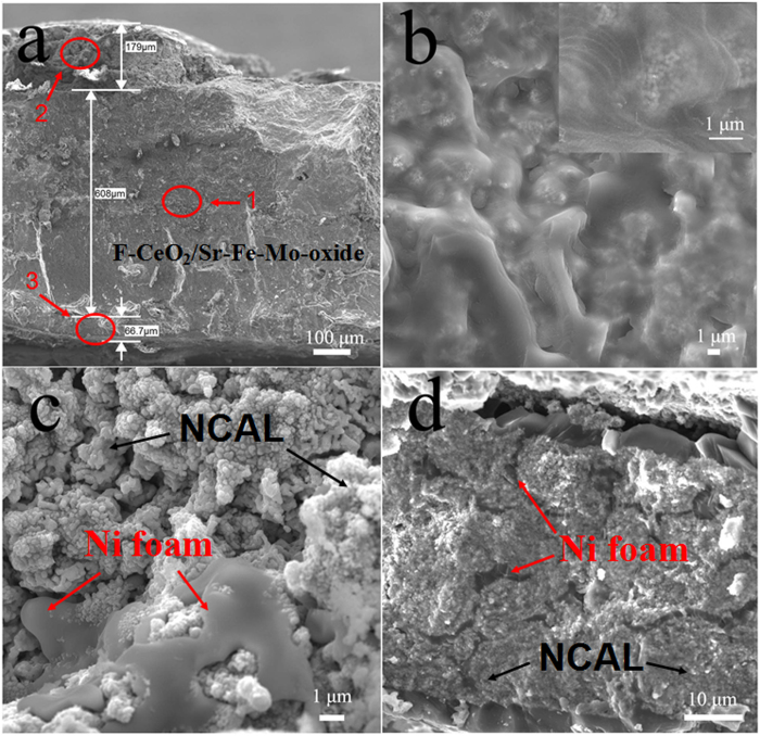
Figure 7 exhibits the SEM micrographs of the device cross-sectional images for details after long-term stability test. As shown in Fig. 7a, the F-CeO2/Sr-Fe-Mo-oxide single layer is 0.6 mm approximately. The thickness of Ni-foam pasted NCAL layer in cathode side and anode side is 179 and 66 μm, respectively. Fig. 7b,c and d are the enlargement for the area 1, 2 and 3 in Fig. 7a. It can be seen that the flowerlike texture of ceria has been destroyed in high temperature and long-term test. However, the initial flowerlike structure results in hierarchical flakes, which induces the Sr-Fe-Mo-oxide homogenously coated on the special flowerlike morphology and microstructure. This may benefit greatly the F-CeO2/Sr-Fe-Mo for high performance LT-SOFCs. The composition of the three regions analyzed by EDX are displayed in Table 1. It can be seen that oxygen content significantly reduced due to the reduction of NCAL-oxide in reducing atmosphere. As shown in Fig. 7c,d, the integration of NCAL and Ni foam layer in cathode and anode sides can contribute to the current collection. Simultaneously, the Ni-foam porous structure provides the tunnels for gas transfer to reach at the F-CeO2/Sr-Fe-Mo-oxide layer.
Figure 7. SEM micrographs of cross-sectional images of.
a) fuel cell configuration; b) F-CeO2/Sr-Fe-Mo-oxide layer; c) Ni foam pasted NCAL in cathode side; d) Ni foam pasted NCAL in anode side after stability test.
Table 1. Composition for F-CeO2/Sr-Fe-Mo-oxide layer, Ni foam pasted NCAL in cathode side and anode side analyzed by EDX.
| Regions | O/wt% | Fe/wt% | Sr/wt% | Mo/wt% | Ce/wt% | Co/wt% | Al/wt% | Ni/wt% |
|---|---|---|---|---|---|---|---|---|
| 1 F-CeO2/Sr-Fe-Mo-oxide layer | 26.14 | 0.31 | 0.63 | 0.58 | 72.34 | − | − | − |
| 2 Ni foam pasted NCAL in cathode side | 10.80 | − | − | − | − | 15.57 | 1.67 | 71.95 |
| 3 Ni foam pasted NCAL in anode side | 1.39 | − | − | − | − | 11.18 | 0.01 | 87.42 |
Discussion
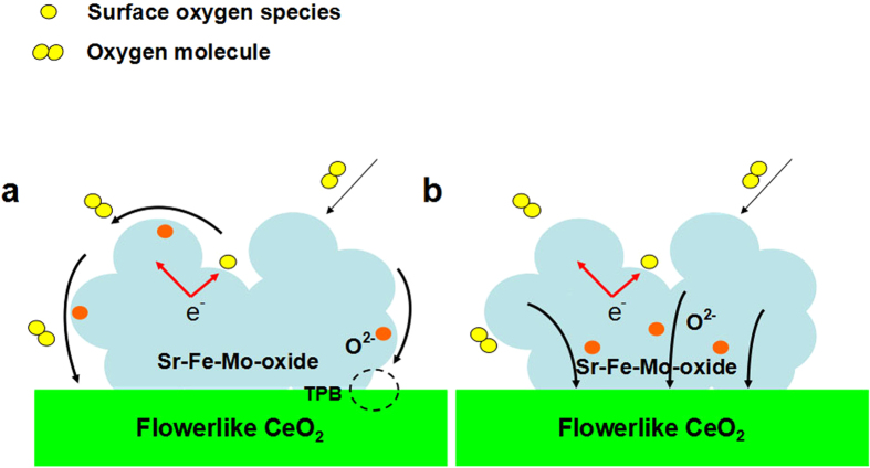
Sr-Fe-Mo-oxide, as a state-of-art mixed ionic and electronic conducting material with a good catalytic activity was successfully coated on the F-CeO2 particles, which provides two paths to promote oxygen reduction reaction (ORR) process occurring at the cathode side of SOFC during operation: bulk and surface (interface) oxygen transfer and transport into F-CeO231,32, as shown schematically in Fig. 8a,b.
Figure 8. Schematically illustration of.
(a) Surface path; (b) bulk path of ORR process.
(1) In the surface process, the Sr-Fe-Mo-oxide particles as an active second phase was highly dispersed on the surface of the F-CeO2 microspheres. The transport of oxygen ions through the electrode was enhanced by the F-CeO2 particles due to the formation of the highly active Sr-Fe-Mo-oxide sites and continuous oxygen ion conducting network on the surface of the F-CeO2 microspheres. The process can be demonstrated clearly in Fig. 8a. Ceria with a fluorite structure is an oxide ionic conductor and its conductivity can be further enhanced by controlling the preparation atmosphere33. In this case, this flowerlike texture provides more surface area to integrate the Sr-Fe-Mo-oxide particles, resulting in large extension of the Sr-Fe-Mo-oxide/F-CeO2/gas triple phase boundary (TPB) length to increase the oxygen surface exchange and charge transfer34,35,36,37. The enhancement of oxygen surface exchange reaction leads to improved cell performance16. The F-CeO2 surface kinetic process is increased via decreasing the re-equilibration time when the Sr-Fe-Mo-oxide particles are deposited38. Usually, the kinetic processes dominate the interfacial polarization resistance during the operation of fuel cells39. Consequently, the resistance is greatly reduced due to the increase of surface kinetic processes. Thus, the cell performance is increased.
(2) In the bulk process, Sr-Fe-Mo-oxide particles coated on the flowerlike CeO2 microsphere surface can promote ORR process occurring at the cathode side through the following mechanism: Sr-Fe-Mo-oxide has high oxygen mobility and large vacancies to interact with the oxygen molecules absorbed on the Sr-Fe-Mo-oxide particle surfaces, which provide fast oxygen dissociation and transport paths for the oxygen and oxygen ions via Sr-Fe-Mo-oxide bulk and surfaces into the F-CeO2 particles to complete the ORR process (as shown in Fig. 8b). Therefore, the two-path promoted ORR process and conductivity enhancement have been achieved by coating Sr-Fe-Mo-oxide on the F-CeO2 microspheres.
In summary, we developed a novel semiconducting and ionic material with new functionalities by coating Sr-Fe-Mo-oxide particles on the flowerlike CeO2 microsphers, which can significantly promote the fuel cell oxygen reduction reaction and ion transport processes. Based on an advanced single layer fuel cell technology, a peak power density of 802 mW cm−2 was obtained using hydrogen as a fuel and air as an oxidant operated at 550 oC. This work may lead to a new path to develop advanced LT-SOFCs.
Methods
Materials preparation
The flowerlike F-CeO2/Sr-Fe-Mo-oxide composite sample was prepared by the following two steps. Firstly, the flowerlike CeO2 was prepared by a hydrothermal method and subsequent cacination as reported in the literature8. Secondly, the preparation of flowerlike F-CeO2/Sr-Fe-Mo-oxide composite sample was as follows. Strontium nitrate, iron nitrate and ammonium molybdate were mixed according to the stoichiometric ratio of 2:1.5:0.5. The mixture was ground thoroughly in an agate mortar to obtain homogeneous Sr2Fe1.5Mo0.5Ox precursor. Then the as-preparation flowerlike ceria and Sr2Fe1.5Mo0.5Ox precursor were grinded again with the content of 4 mol% Sr2Fe1.5Mo0.5Ox precursor to obtain homogeneous flowerlike CeO2-Sr2Fe1.5Mo0.5Ox precursor. The resulting materials were transferred into ceramic crucible following a sintering process at 750 oC for 2 h. The final sample obtained via thorough grinding was noted as F-CeO2/Sr-Fe-Mo-oxide composite.
The NCAL is initials for Ni0.8Co0.15Al0.05Li-oxide was purchased from Tianjin Baomo Joint Hi-Tech venture, China.
Characterization of materials
Powder X-ray diffraction (XRD) analysis was carried out using D-max-2500 X-ray diffractometer (Rigaku Corp., Japan) with Ni-filtered Cu Kα radiation (λ = 1.54056 Å). The patterns were recorded at the 2θ range of 10–90o with step size of 0.02o. Scanning electron microscopy (SEM) was performed on a cold field emission scanning electron microscope (Hitachi S-4800).
Electrochemical impedance spectroscopy (EIS) was carried out to measure the electrical conductivity of the prepared material F-CeO2 coated with Sr-Fe-Mo-oxide composite from 600 oC to 400 oC upon cooling at an interval of 50 oC. The measured frequency was ranging from 0.01 Hz to 1 MHz under a bias voltage of 10 mV.
Fuel cell preparation and measurement
The fuel cell was fabricated using a new fuel cell technology in a simple symmetrical configuration using the prepared F-CeO2/Sr-Fe-Mo-oxide sample as the single component material and NCAL was pasted on foam nickel as anode side and cathode side. Simultaneously, the conducting transition metal oxide NCAL can play a role as current collector. The two more pure foam nickel were pressed slightly on both sides while mount the pellet on the testing device to provide the channels to exhaust water vapor. The cell configuration can be simply denoted as Ni pasted NCAL NCAL | F-CeO2 | Sr-Fe-Mo-oxide | NCAL pasted on Ni foam. The fuel cell were compressed at a pressure of 200 MPa for 2 min with an active area of 0.64 cm2, the thickness and diameter were 2 mm and 13 mm, respectively.The cell was tested on the computerized instrument (IT8511 + 120 V/30A/150 W) using hydrogen as fuel and air as oxidant operated at 550oC, respectively. The flow rate of H2 is in the range of 80 ~ 120 ml min−1 and the flow rate of air is 100 ml min−1under an atmospheric pressure.
Additional Information
How to cite this article: Liu, Y. et al. Flowerlike CeO2 microspheres coated with Sr2Fe1.5Mo0.5Ox nanoparticles for an advanced fuel cell. Sci. Rep. 5, 11946; doi: 10.1038/srep11946 (2015).
Acknowledgments
Prof Bin Zhu acknowledges the support of the National Natural Science Foundation of China (NSFC) (Grant Nos.51402093 and 51202213), the Swedish Research Council (VR, Contract No. 621-2011-4983) and the EC FP7 TriSOFC project (Contract No.303454). Prof Bin Zhu also appreciates the 100 talent overseas program in Hubei province and distinguished professor in Hubei University. Prof Chunwen Sun gratefully acknowledges the financial support by the National Science Foundation of China (NSFC) (Grant Nos. 51172275 and 51372271) and the National Key Basic Research Program of China (Grant Nos. 2012CB215402). Dr Yongfu Tang acknowledges the support of the National Natural Science Foundation of China (NSFC) (Grant Nos.21406191).
Footnotes
Author Contributions Y.Y.L. and Z.H.M. have made experiments. Y.F.T. and W.J.D. supported to analyze the experimental results. C.W.S. and Y.J.H. supported the scanning electron microscope tests. M.S. and C.W.S supported to polish the language. Y.Y.L., Y.F.T., C.W.S. and B.Z. finalized the manuscript format and submission. B.Z. designed and supervised all experiments and manuscripts as well as final revision.
References
- Dong X. et al. Single layer fuel cell based on a composite of Ce0.8Sm0.2O2-δ-Na2CO3 and a mixed ionic and electronic conductor Sr2Fe1.5Mo0.5O6-δ. J. Power Sources. 249, 270–276 (2014). [Google Scholar]
- Raza R. et al. Advanced Multi-Fuelled Solid Oxide Fuel Cells (ASOFCs) Using Functional Nanocomposites for Polygeneration. Adv. Energy Mater. 1, 1225–1233 (2011). [Google Scholar]
- Zhu B., Fan L. D. & Lund P. Breakthrough fuel cell technology using ceria-based multi-functional nanocomposites. Appl. Energy. 106, 163–175 (2013). [Google Scholar]
- Sun C. W., Li H. & Chen L. Q. Nanostructured Ceria-based Materials: Synthesis, Properties, and Applications, Energ. Environ. Sci. 5, 8475–8505 (2012). [Google Scholar]
- Xiao G., Li S., Li H. & Chen L. Synthesis of doped ceria with mesoporous flowerlike morphology and its catalytic performance for CO oxidation. Microporous and Mesoporous Mater. 120, 426–431 (2009). [Google Scholar]
- Sun C. W., Xie Z., Xia C. R., Li H. & Chen L. Q. Investigations of mesoporous CeO2-Ru as a reforming catalyst layer for solid oxide fuel cells. Electrochem. Commun. 8, 833–838 (2006). [Google Scholar]
- Sun C. W., Li H. & Chen L. Q. Study of flowerlike CeO2 microspheres used as catalyst supports for CO oxidation reaction. J. Phys. Chem. Solids. 68, 1785–1790 (2007). [Google Scholar]
- Sun C. W. et al. Mesoscale organization of nearly monodisperse flowerlike ceria microspheres. J. Phys. Chem. B. 110, 13445–13452 (2006). [DOI] [PubMed] [Google Scholar]
- Liu Q., Dong X. H., Xiao G. L., Zhao F. & Chen F. L. A novel electrode material for symmetrical SOFCs. Adv. Mater. 22, 5478–5482 (2010). [DOI] [PubMed] [Google Scholar]
- He B. B. et al. Sr2Fe1.5Mo0.5O6-δ-Sm0.2Ce0.8O1.9 Composite Anodes for Intermediate-Temperature Solid Oxide Fuel Cells. J. Electrochem. Soc. 159, B619–B626 (2012). [Google Scholar]
- Wang Y. L., Hu B. B., Zhu Z. Y., Bouwmeester H. J. M. & Xia C. R. Electrical conductivity relaxation of Sr2Fe1.5Mo0.5O6-d-Sm0.2Ce0.8O1.9 dual-phase composites. J. Mater. Chem. A. 2, 136–143 (2014). [Google Scholar]
- Dai N. N. et al. Synthesis and characterization of B-site Ni-doped perovskites Sr2Fe1.5-xNixMo0.5O6-δ (x=0,0.05,0.1,0.2,0.4) as cathodes for SOFCs. J. Mater. Chem. A. 45, 14147–14153 (2013). [Google Scholar]
- Liu Q. et al. Sr2Fe1.5Mo0.5O6-δ as a regenerative anode for solid oxide fuel cells. J. Power Sources. 22, 9148–9153 (2011). [Google Scholar]
- Xiao G. L. et al. Sr2Fe1.5Mo0.5O6 as cathodes for intermediate-temperature solid oxide fuel cells with La0.8Sr0.2Ga0.87Mg0.13O3 electrolyte. J. Electrochem. Soc. 5, B455–B460 (2011). [Google Scholar]
- Zhu B. et al. Functional semiconductor-ionic composite GDC-KZnAl/LiNiCuZnOx for single-component fuel cell. RSC Adv. 4, 9920–9925 (2014). [Google Scholar]
- Zhu B. et al. A new energy conversion technology based on nano-redox and nano-device processes. Nano Energy. 2, 1179–1185 (2013). [Google Scholar]
- Zhu B. et al. A fuel cell with a single component functioning simultaneously as the electrodes and electrolyte. Electrochem. Commun. 13, 225–227 (2011). [Google Scholar]
- Zhu B., Raza R., Abbas G. & Singh M. An Electrolyte-Free Fuel Cell Constructed from One Homogenous Layer with Mixed Conductivity. Adv. Funct. Mater. 21, 2465–2469 (2011). [Google Scholar]
- Fuel cells: Three in one (research highlights). Nat. Nanotechnol. 6, 330 (2011). [Google Scholar]
- Hu H. Q., Lin Q. Z., Zhu Z. G., Zhu B. & Liu X. R. Fabrication of electrolyte-free fuel cell with Mg0.4Zn0.6O/Ce0.8Sm0.2O2−δ–Li0.3Ni0.6Cu0.07Sr0.03O2−δ layer. J. Power Sources. 248, 577 (2014). [Google Scholar]
- Ma Y. et al. Samarium-Doped Ceria Nanowires: Novel Synthesis and Application in Low-Temperature Solid Oxide Fuel Cell. Adv. Mater. 22, 1640–1644 (2010). [DOI] [PubMed] [Google Scholar]
- Cai T. X., Zeng Y. W., Yin S. L., Wang L. & Li C. M. Preparation and characterization of Ce0.8Sm0.2O1.9 (SDC)-carbonates composite electrolyte via molten salt infiltration. Materials Lett. 65, 2751–2754 (2011). [Google Scholar]
- Dusastre V., Kilner J. A. Optimisation of composite cathodes for intermediate temperature SOFC applications. Solid State Ionics. 126, 163–174 (1999). [Google Scholar]
- Huang K., Feng M., Goodenough J. B. Synthesis and electrical properties of dense Ce0.9Gd0.1O1.95 ceramics. J. Am. Ceram. Soc. 81, 357–362 (1998). [Google Scholar]
- Mai A. et al. Time-dependent performance of mixed-conducting SOFC cathodes. Solid State Ionics 19, 1965–1968 (2006). [Google Scholar]
- Hu H. Q. Lin Q. Z. Zhu Z. G. Liu X. R. & Zhu B. Time-dependent performance change of single layer fuel cell with Li0.4Mg0.3Zn0.3O/Ce0.8Sm0.2O2−δ composite. Int. J. Hydrogen Energy. 20, 10718–10723 (2014). [Google Scholar]
- Zhu W. Z. & Deevi S.C. Development of interconnect materials for solid oxide fuel cells. Mater. Sci. Eng. A. 1, 227–243 (2003). [Google Scholar]
- Lin T. N. et al. Chemical state identification of Ce3+/Ce4+ in the Sm0.2Ce0.8O2−δ electrolyte for an anode-supported solid oxide fuel cell after long-term operation. Mater. Lett. 81, 185–188 (2012). [Google Scholar]
- Choudhury B. & Choudhury A. Ce3+ and oxygen vacancy mediated tuning of structural and optical properties of CeO2 nanoparticles. Mater. Chem. Phys. 3, 666–671 (2012). [Google Scholar]
- Park P. W. & Ledford J. S. Effect of crystallinity on the photoreduction of cerium oxide: A study of CeO2 and Ce/Al2O3 catalysts. Langmuir. 7, 1794–1799 (1996). [Google Scholar]
- Feng J. et al. Investigation into the effect of Fe-site substitution on the performance of Sr2Fe1.5Mo0.5O6−δ anodes for SOFCs. J. Mater. Chem. A. 2, 17628–17634 (2014). [Google Scholar]
- Lee Y. L., Kleis J., Rossmeisl J., Shao-Horn Y. & Morgan D. Prediction of solid oxide fuel cell cathode activity with first-principles descriptors. Energy Environ. Sci. 4, 3966–3970 (2011). [Google Scholar]
- Mogensen M., Sammes N. M. & Tompsett G. A. Physical, chemical and electrochemical properties of pure and doped ceria. Solid State Ionics. 129, 63–94 (2000). [Google Scholar]
- Wei T., Zhang Q., Huang Y. H. & Goodenough J. B. Cobalt-based double-perovskite symmetrical electrodes with low thermal expansion for solid oxide fuel cells. J. Mater. Chem. 22, 225–231 (2012). [Google Scholar]
- Dai N. N. et al. One-step synthesis of high performance Sr2Fe1.5Mo0.5O6-Sm0.2Ce0.8O1.9 composite cathode for intermediate-temperature solid oxide fuel cells using a self-combustion technique. J. Power Sources. 217, 519–523 (2012). [Google Scholar]
- Dai N. N. et al. Synthesis and electrochemical characterization of Sr2Fe1.5Mo0.5O6-Sm0.2Ce0.8O1.9 composite cathode for intermediate-temperature solid oxide fuel cells. J. Power Sources. 243, 766–772 (2013). [Google Scholar]
- Liu S. M., Suo J. P. & Xiao J. Z. Effects of surface overpotential at the La1-xSrxCo1-yFeyO3-yttria stabilized zirconia interface in a model solid oxide fuel cell cathode. Int. J. Hydrogen Energ. 33, 6322–6326 (2008). [Google Scholar]
- Zhang L. et al. Enhancement in surface exchange coefficient and electrochemical performance of Sr2Fe1.5Mo0.5O6 electrodes by Ce0.8Sm0.2O1.9 nanoparticles. Electrochem. Commun. 13, 711–713 (2011). [Google Scholar]
- Adler S. B., Lane J. A. & Steele B. C. H. Electrode Kinetics of Porous Mixed-Conducting Oxygen Electrodes. J. Electrochem. Soc. 143, 3554–3564 (1996). [Google Scholar]


