

Abstract
Iron oxide nanoparticles are formidable multifunctional systems capable of contrast enhancement in magnetic resonance imaging; guidance under remote fields; heat generation; and biodegradation. Yet, this potential is underutilized in that each function manifests at different nanoparticle sizes. Here, sub-micrometer discoidal magnetic nanoconstructs are realized by confining 5 nm ultra-small super-paramagnetic iron oxide nanoparticles (USPIOs) within two different mesoporous structures, made out of silicon and polymers. These nanoconstructs exhibit transversal relaxivities up to ~10 times (r2 ~ 835 (mM·s)−1) higher than conventional USPIOs and, under external magnetic fields, collectively cooperate to amplify tumor accumulation. The boost in r2 relaxivity arises from the formation of mesoscopic USPIO clusters within the porous matrix, inducing a local reduction in water molecule mobility as demonstrated via molecular dynamics simulations. The cooperative accumulation under static magnetic field derives from the large amount of iron that can be loaded per nanoconstuct (up to ~ 65 fg) and the consequent generation of significant inter-particle magnetic dipole interactions. In tumor bearing mice, the silicon-based nanoconstructs provide MRI contrast enhancement at much smaller doses of iron (~ 0.5 mg of Fe/kg animal) as compared to current practice.
Keywords: MRI, magnetic nanoparticles, magnetic guidance, relaxivity, mesoporous matrices
1. Introduction
Iron oxide nanoparticles (IOs) exhibit interesting multi-functional properties that could be used in a variety of biomedical applications.[1–3] However, a major impediment to their full utilization is that these properties manifest over different, not overlapping, size intervals. In magnetic resonance imaging (MRI), IOs with a diameter smaller than 100 nm induce significant shortening in transversal relaxation times, T2.[4–8] On the other hand, only micron and sub-micron sized IOs have been efficiently manipulated in vivo by remote static magnetic fields.[9–13] In therapeutic applications, 20 – 50 nm IOs have been used as nanoheaters in that, under alternating magnetic fields, they can generate significant doses of thermal energy for ablating the surrounding malignant tissue, sensitizing cells in adjuvant therapies, and triggering the release of active molecules.[10, 14–16] Moreover, IOs smaller than ~ 20 nm could be fully degraded and metabolized over a few days.[16–19] A novel strategy is needed to effectively decouple the IO functions from the particle size in order to fully capitalize on the multiple functionalities.
MRI is considered a powerful tool in tumor imaging because of its non-invasiveness and high spatial resolution. However, clinically-available products, such as Feridex®, often exhibit relatively low transversal relaxivities (r2), typically of about 100 (mM·s) −1.[2, 18] Different strategies have been explored to improve the MRI performance of IO-based contrast agents, including: the modulation of their size, shape and surface properties; and the use of metal alloys. It is well documented that r2 can be enhanced by increasing the size of the magnetic core,[20] using cubically-shaped nanoparticles,[16, 21] and decorating the particle surface with molecules and polymers.[22] Also, the inclusion of atoms such as Co, Mn, Ni in the magnetic core has improved the relaxometric response.[23–25] However, none of the listed approaches can successfully combine together the multiple functionalities of the IOs. Recently, it has been realized that IO clusters can also provide higher relaxivities when compared to individual particles.[26–28] However, such an enhancement is strictly depending on the spatial organization and level of hydration of IOs. Moreover, controlling and preserving the state of aggregation of the USPIO clusters in vivo, upon systemic injection, without compromising their biodistribution are major, unsolved challenges.
Contrast enhancement and therapeutic efficacy are directly related to the amount of IOs accumulated at the diseased site. Although IOs with ‘stealth’ coatings tend to circulate longer, thus offering a higher probability of passive accumulation within the tumor mass,[2] the amount of IOs reaching the tumor site can be much smaller than 1% of the injected dose per gram tissue (% ID/g).[29] Remote guidance via external magnetic fields has been proposed as a way to attract more IOs within the target tissue.[9, 13] However, magnetic forces scale proportionally to the particle volume and drop rapidly as the IO diameter decreases, being negligibly small, as compared to hydrodynamic and colloidal interactions, for particles of a few tens of nanometers. Also, the magnetic force reduces with the distance from the magnet and the penetration depth.[13, 30] Therefore, not surprisingly, magnetic targeting has provided some success only for particles larger than 100 nm and injected doses of the order of 10 mg of Fe/kg of animal.[9, 13]
Here, to fully capitalize on the intrinsic multi-functional capabilities of IOs, a novel approach is proposed to boost the relaxivity r2; enhance tumor accumulation by remote magnetic guidance; and, possibly, enable hyperthermia treatments upon systemic injection. This is obtained by dispersing multiple clusters of small USPIOs within the mesoporous matrix of larger particles, thus leading to the formation of multiscale, hierarchically-organized magnetic nanoconstructs. The versatility and generality of the approach is also demonstrated by considering two different nanotechnological platforms, namely sub-micron sized mesoporous silicon particles (SiMPs) and discoidal polymeric nanoconstructs (DPNs). Commercially-available USPIOs are used with a nominal magnetic core diameter of 5 nm. The SiMPs and DPNs have been rationally designed to deposit within the tumor vasculature by relying on the balance between hydrodynamic dislodging forces and interfacial adhesion interactions with the blood vessel walls.[31,32–34] In this manuscript, first, the USPIO loading efficiency and the stability of the resulting nanoconstructs have been analyzed, under physiologically relevant conditions. Secondly, the relaxometric and magnetic guidance response of the nanoconstructs have been characterized in vitro. Finally, for the SiMPs which have been extensively tested in vivo,[33–35] the MRI and magnetic guidance performance have been demonstrated in a melanoma mouse model using a 3T MRI clinical scanner.
2. Results and Discussion
2.1. Assembly of the magnetic nanoconstructs
The schematic representations of our two magnetic nanoconstructs are presented in Figure 1a, including: discoidal mesoporous silicon particles (SiMPs) with a diameter of ~1,000 nm and a thickness of ~400 nm; porous discoidal PLGA/PEG nanoconstructs (DPNs) with a diameter of ~1,000 nm and a thickness of ~500 nm. USPIOs with a magnetic core diameter of 5 nm were examined for the loading and characterization, with hydrophilic and hydrophobic coatings, depending on the host matrix properties. Data on the physico-chemical properties of the USPIOs, SiMPs, and DPNs are reported in the Supporting Information.
Figure 1.

Magnetic nanoconstructs and USPIOs distribution. a, Ultra small superparamagnetic iron oxide nanoparticles (USPIOs) are loaded within the porous structure of 1,000×400 nm discoidal silicon particles (SiMPs); 1,000×500 nm discoidal PLGA/PEG nanoconstructs (DPNs). Mesoscopic clusters of USPIOs are formed within the porous structure leading to multiscale, hierarchically structured magnetic nanoconstructs. Energy Dispersive X-Ray (EDX) – TEM mapping b for the SiMPs; c for the DPNs. These maps show the distribution of the most abundant element (i.e. silicon – Si –for the SiMPs and carbon – C –for the DPNs) and the dispersion of 5 nm USPIOs with the corresponding porous matrix (red dots in the third column). Note the formation of multiple, mesoscopic clusters of USPIOs within the two different matrices, one mesoporous silicon and one polymeric. (scale bar: 100 nm)
The USPIOs are loaded within the SiMP pores via capillary action by directly exposing dry SiMPs to a concentrated stock solution of hydrophilic USPIOs; whereas for the DPNs, hydrophobic USPIOs are mixed with the polymeric paste during the synthesis process. Note that the geometrical and magnetic properties of the hydrophobic and hydrophilic 5 nm USPIOs are comparable (Supporting Information). The resulting nanoconstructs were then analyzed using TEM, coupled with energy-dispersive X-ray (EDX-TEM), to confirm USPIO loading and document on their spatial distribution within the porous matrix. The EDX mappings of Si and Fe for the SiMPs (Figure 1b) show the fine porous structure of the nanoconstructs, with lateral and internal walls, and a quite uniform distribution of USPIOs (red spots) across the porous matrix. Similarly for the DPNs, Figures 1c demonstrates the loading of USPIOs (red dots) within the polymeric matrix. EDX mapping for carbon identifies also the external boundaries of the nanoconstructs, as confirmed by the corresponding TEM images. The presence of Fe in the two nanoconstructs is also documented by EDX spectral analysis and magnetic force microscopy (Supporting Information). The images in Figure 1 eloquently show that the USPIOs tend to form mesoscopic clusters dispersed throughout the matrix of the resulting magnetic nanoconstruct.
The mass of USPIOs loaded per SiMP and DPN is given in Figure 2a: up to 15.5 ± 2.5 × 10⁻⁹ μg of 5 nm USPIOs are loaded per SiMP; and 65.17±4.58 × 10⁻⁹ μg are confined within the DPNs. Inductively coupled plasma optical emission spectroscopy (ICP – OES) was performed on the element Fe for quantifying the mass of loaded USPIOs.
Figure 2.

USPIO loading and stability of the magnetic nanoconstructs. a, The mass of USPIOs loaded within the mesoporous nanoconstructs is measured via inductively coupled plasma optical emission spectroscopy (ICP-OES). b, The percentage of USPIOs released from a mesoporous SiMP is measured as a function of the incubation time in a buffer solution, agitated at 60 rpm and 37°C. c-e, Scanning electron micrographs showing the morphology of the SiMPs at three different incubation time points, namely 3, 6 and 24h. The inset in e, shows the uneven degradation of the SiMPs that tend to assume a mushroom shape. (scale bar: 1.0 μm)
As the USPIO/SiMP nanoconstructs will be later used for in vivo studies, it is here important to analyze their stability, in that it is well known that porous silicon spontaneously degrades into orthosilicic acid under physiological conditions, thus releasing its payload.[36, 37] A stability test was performed by exposing 5 nm USPIO-loaded SiMPs to a buffer solution, agitated over time at 60 rpm and 37°C. After 24h of incubation, only 24.0 ± 2.8% of the originally loaded USPIOs were released upon silicon degradation (Figure 2b). SEM images of the magnetic nanoconstructs at different time points during the degradation process, namely 3, 6 and 24h, are shown in Figure 2c–e. Significant changes in the SiMP geometry are solely visible at 24h. This is consistent with previous data by the authors showing that PEG chains, here decorating the USPIOs, modulate the interaction of the solution with the silicon walls, thus slowing the degradation process.[37] The stability and biodegradation properties of the DPNs have been demonstrated previously by the authors.[38, 39]
2.2. Relaxometric characterization of the magnetic nanoconstructs
The authors have recently shown that the geometrical confinement of Gd3+-based MRI contrast agents within mesoporous structures enhances their longitudinal relaxometric response.[40, 41] To study the effect of USPIO confinement within porous matrices, the longitudinal (T1) and transverse (T2) relaxation times of our two magnetic nanoconstructs were measured by a bench-top relaxometer operating at 60 MHz (1.41 T) and at 37°C. The ability of any material to act as a MRI contrast agent (CA) is expressed in terms of its relaxivity ri, defined as the change in relaxation rate of water protons brought about by mM concentration of CA. The relaxivities r1,2 of the nanoconstructs were calculated using the classical formula r1,2 = (T1,2−1 – T0−1)/[Fe], To being the diamagnetic contribution, and [Fe] the iron concentration in mM. Upon confinement within a porous matrix, the USPIOs exhibited a significant increase in transversal relaxivity r2 compared to free USPIOs in bulk solution (Figure 3a). It increases from 107±24 to 270±73 (mM·s) −1 for the 5 nm USPIOs (2.5 times) loaded into the SiMPs. For the DPNs, the transversal relaxivity r2 is 835±63 (mM·s) −1, which is ~ 10-fold higher than what measured for clinically relevant USPIOs. Note that for the DPNs, the actual r2 enhancement cannot be directly quantified in that these nanoconstructs were obtained by dispersing hydrophobic 5 nm USPIOs within a porous polymeric matrix. On the other hand, no relevant changes are observed for the longitudinal relaxivity r1. A contrast agent is classified as T1-weighted or T2-weighted based on their r2/r1 ratio, and a r2/r1 > 2 implies that the agent is more effective as a T2-weighted contrast agent.[2] A significant increase in the r2/r1 ratio is observed for all USPIOs upon confinement within the porous matrix of the hosting nanoconstructs.
Figure 3.
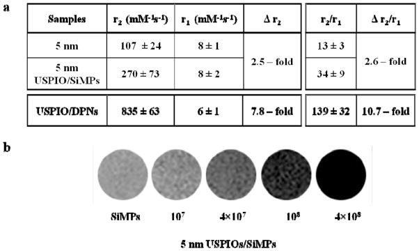
Relaxometric characterization of the magnetic nanoconstructs. a, The transversal (r2) and longitudinal (r1) relaxivities, and the r2/r1 ratio are listed for the free USPIOs and the corresponding USPIO-loaded nanoconstructs, as derived from a bench-top relaxometric analysis. The change in transversal relaxivity Δr2 and Δr2/r1 ratio is also provided, showing a significant enhancement in MRI performance for all configurations. Note that for the DPNs, the enhancement is calculated with respect to the hydrophilic 5 nm USPIOs. b, Phantom images for different concentrations of the 5 nm USPIO-loaded SiMPs (magnetic nanoconstructs) generated using a 3T Philips MRI clinical scanner. Note that 107 SiMPs are equivalent to ~ 0.2 μg of Fe.
The contrast enhancement efficacy of the magnetic nanoconstructs under clinical settings was tested in a 3T MRI scanner (Philips Ingenia®). Figure 3b shows the phantom images for different numbers of magnetic nanoconstructs embedded in 1% agarose. The phantom images show that the magnetic nanoconstructs are effective under clinical settings, and even a small number of nanoconstructs can generate sufficient contrast. For the DPNs, similar phantom images are also provided in the Supporting Information. The relaxometric results and phantom images demonstrate the superior performance of the nanoconstructs compared to free USPIOs in solution.
The observed enhancement in the r2 relaxivity should be ascribed to the hierarchical organization of the USPIOs within the hosting matrix (see TEM and EDX analysis in Figure. 1 and Supporting Information). Differently from what observed for the longitudinal relaxivity enhancement,[40] here, r2 is mostly affected by the formation of USPIO clusters and the so called outer sphere mechanism.[42] In general, the transversal relaxivity r2 increases with the particle magnetization (∝ Ms2) and with the inverse of the diffusion (∝ Dw−1) of the water molecules surrounding the magnetic core ( ). However, given the hydrophobicity of the polymer (PLGA) forming the cores of the DPNs, the well know lower mobility of water molecules within mesoporous structures, and the variety of USPIO clusters generated within the two different matrices, it is reasonable to speculate that, under such configuration, Dw could play a major role. (Figure. 1 and Supporting Information). To better elucidate the mechanisms regulating the r2 enhancement, a molecular dynamics (MD) model was developed for the USPIO confinement within mesopores. The geometry of the model is depicted in Figure 4a, where an individual USPIO is shown first, followed by 1, 4 and 8 couples of USPIOs confined within a periodic slice of a mesopore. The model allows for computing changes in the diffusion of water molecules Dw as a function of the loading conditions (number of USPIOs per pore slice) and surface properties of the USPIOs (polymer chain length and density). Note that the USPIOs form multiple mesoscopic clusters in the nanoconstructs, within which the water molecule mobility is impaired mostly by geometrical constriction (Figure 4a). Details about the MD model are provided in the Supporting Information. The computed coefficient of diffusion, Dw, is presented in Figure 4b. The calculations were performed for three strengths of the Lennard-Jones (LJ) potential, in order to explore how the observed behavior depends on the actual properties of the USPIO surface (i.e. different polymer chain length and density). Starting from free bulk water (Dw = 2.7×10⁻⁹ m2s−1), the coefficient Dw reduces as the number of loaded USPIOs increases, being ~ 2.1×10⁻⁹ m2s−1 for 1 couple of USPIOs (25% decrease), ~ 1.4×10⁻⁹ cm2s−1 for 4 couples of USPIOs (50% decrease), and ~ 0.4×10⁻⁹ m2s−1 for 8 couples of USPIOs (85% decrease). Note that Dw is computed by averaging over the pore cross-section, thus even lower water mobilities are expected in the immediate vicinity of the USPIOs, and in the interspaces between the USPIOs and the pore walls. These data show that a 85% decrease in the diffusion of water molecules Dw is likely to occur in USPIOs-loaded nanoconstructs, and this would already justify a 4-fold increase in r2. Remarkably, even a reduction by an order of magnitude in the LJ potential seems to be accompanied by only a tiny increase in water mobility. Since the strength of the interaction potential is also affected by the adsorption of molecules on the particle surface, the mild effect of the LJ potential on Dw would suggest that water confinement is governing the relaxivity enhancement. The mechanism proposed above is in agreement with the observations of Gillis and colleagues on the magnetic relaxation properties of USPIO clusters.[43]
Figure 4.

Molecular Dynamics simulation for the self-diffusion coefficient of water in a mesopore. a, Molecular Dynamics representation of an individual USPIO, a couple, 4 couples and 8 couples of USPIOs adsorbed on the walls of a mesopore with a hydrated silicon surface. b, Computed diffusivity of the water molecules, averaged over the cross-section of the mesopore, presented as a function of the loading conditions (1, 4 and 8 couples of USPIOs per periodic slice of a mesopore, corresponding to 6%, 24% and 48% of the maximum geometrical loading) and strength of the Lennard-Jones potential. Error bars indicate 98% confidence intervals based on Student’s t distribution associated with four Dw measurements upon the achievement of steady state conditions. Variable LJ potentials allow one to explore the effects due to the actual surface properties (i.e. different pegylation levels).
It is here important to emphasize that transversal relaxivities r2 higher than 300 (mM·s) −1 have been demonstrated with individual, high-performance IOs.[21, 24, 25, 44] However, in these cases, the enhancement in relaxivity is mainly due to the improvement of the intrinsic magnetic properties of the nanoparticles rather than the modulation of the local water mobility. Therefore, it is reasonable to speculate that the geometrical confinement of these high-performance IOs within the proposed mesoporous nanoconstructs could boost even more their original MRI relaxivities.
2.3. Remote guidance of the magnetic nanoconstructs and cooperative accumulation
The loading data of Figure 2a demonstrate that over 4.0×10⁴ USPIOs are loaded into a single SiMP, and this number grows of about 1 order of magnitude, ~ 2.0×10⁵ USPIOs per nanoconstructs, in the case of DPNs (5 nm core; USPIO density of 5.17×10³ kg/m3). This provides a huge, localized concentration of Fe that is equivalent in volume to a spherical bead of several hundreds of nanometers in diameter. With these premises, the magnetic guidance of our two nanoconstructs under an external static field was tested in a quiescent fluid (Supporting Information) and under flow, using a parallel plate flow chamber apparatus.[45] This is schematically presented in Figure 5a, showing a flat, cylindrical magnet located underneath the chamber. The magnetic nanoconstructs were injected in the chamber through the inlet bore using a syringe pump and their dynamics under flow was monitored with bright field microscopy. From imaging post-processing (Supporting Information), the trajectories and velocities of the nanoconstructs were extracted as a function of their initial separation distance from the magnet. The in-plane nanoconstruct velocity is decomposed in the longitudinal component, vx, aligned with the flow; and the transversal component, vy, orthogonal to the flow and oriented towards the magnet. Figure 5b shows the normalized velocity vy/(Sh) increasing steadily from zero to about 0.002, corresponding to ~ 10 μm/s, at 50 μm away from the magnet. Similarly, the angle θ between the flow direction and the particle trajectory varies significantly ranging from 0 to over 30°, as the nanoconstruct approaches the magnet. Only minor changes are observed for vx. The inset of Figure 5c shows a dark corona originating from the progressive deposition of nanoconstructs around the magnet. These pictures have been taken on the flow chamber coverslip after the magnet removal. Supporting Videos 1 – 3 document on the rapid deceleration and abrupt change in direction experienced by the nanoconstructs as they enter the magnetic field. Interestingly, small clusters of magnetic nanoconstructs, deposited on the bottom of the chamber, tend to attract and affect individual nanoconstructs passing nearby.
Figure 5.

Remote guidance of the magnetic nanoconstructs and cooperative accumulation. a, Schematic of the parallel plate flow chamber apparatus used for testing the guidance of the magnetic nanoconstructs under controlled biophysical conditions. The static magnet was placed underneath the chamber, on the side and the nanoconstruct solution was infused via a syringe pump through the inlet bore. b, The variation of the longitudinal and transversal components of the nanoconstruct velocity, vx and vy, normalized with the chamber height h and wall shear rate S; and of the angle θ between the flow direction and the particle trajectory with the separation distance from the magnet. (black diamonds are for the SiMPs; triangles are for the DPNs) c, Image of a dark corona originating from the progressive accumulation of nanoconstructs around the magnet. d, Bright field microscopy images of SiMP nanoconstructs depositing on the bottom of the parallel plate flow chamber (S = 15−1 sec). f, Fluorescent microscopy images of DPN nanoconstructs depositing on the bottom of the parallel plate flow chamber (S = 15−1 sec). e,g, Four representative nanoconstruct clusters are identified for the SiMPs and DPNs by dashed circles and their relative area variation ΔA% is plotted over time.
In order to better characterize the mutual interaction of the nanoconstructs under static magnetic fields, the experiments under flow were also performed in the presence of small clusters of nanoconstructs pre-formed on the bottom of the flow chamber (green dotted circles in Figure 5d and 5f, and Supporting Information at t = 0 min). A few drops of a solution containing the nanoconstructs were deposited on the coverslip and left to dry in air, while a static magnet was placed underneath the coverslip. After complete drying, the coverslip with the pre-formed clusters was assembled with the rest of the parallel plate flow chamber apparatus and the actual experiment was performed using a new solution of the nanoconstructs. USPIO-loaded SiMPs or DPNs were then injected in the parallel plate flow chamber and the size of the four representative clusters was monitored over time (Figure 5e and 5g). These experiments were performed in the presence of an external magnetic field and, as a control, without any field. Figure 5d and 5f show microscopy images of the region of interest at the bottom of the chamber at the initial time (t = 0 min) and at the end of the experiment, for SiMPs and DPNs respectively. The relative variation of the area associated with four representative clusters (ΔA%) is plotted as a function of time in Figure 5e and 5g. The areas of these clusters continuously grow over time demonstrating the progressive accumulation of individual nanoconstructs around the pre-formed clusters (see also, Supporting Movies 4 and 5). No variation in cluster size and numbers was observed in the control experiments, where a magnet was not used (Supporting Information). The magnetic nanoconstructs, exposed to remote magnetic fields, tend to behave locally as small, non-permanent magnetic dipoles. This would enhance locally the magnetic field and its gradient favoring particle-particle mutual interaction and attraction. This cooperative mechanism is also expected to operate in vivo, favoring the progressive accumulation of nanoconstructs, particularly in the smaller blood vessels.
2.4. MR imaging in orthotopic mouse models of melanoma
The MRI and cooperative accumulation properties are demonstrated in vivo for the SiMPs. The in vivo performance of SiMPs has been extensively documented in different animal models for optical imaging and therapy.[33–35] In particular, the authors have shown that discoidal SiMPs of 1,000 x 400 nm can reach tumor accumulation levels of up to 5% of the injected dose per gram tissue.[34] This results from the specific selection of the particle size and shape (i.e. particle geometry) that favors vascular deposition by increasing the interfacial adhesion interactions and reducing the dislodging hydrodynamic forces.[45]
B16-F10 cells were grown in the flank of a mouse for 10 – 15 days before the injection of 5.0×10⁸ nanoconstructs in 150 μL of phosphate buffered saline via tail vein. This dose corresponds to ~ 8 μg of USPIOs per mouse (i.e. ~ 0.5 mg of Fe/kg). Three different groups were considered: i) free 5 nm USPIOs with an external magnet (n = 3 mice); ii) nanoconstructs without an external magnet (n = 3 mice); and iii) nanoconstructs with an external magnet (n = 6 mice). The magnet was placed on the tumor side for 4h post injection and the comparison among the three groups was performed fixing the total amount of injected iron. The mice were imaged pre-injection as a control, at 4h, after the removal of the magnet, and at 24h post injection, just before sacrifice using a 3T MRI clinical scanner. Figure 6 shows MR images and intensity ratios at the three different time points, and for the three experimental groups. The tumor is visible on the right flank of the animal. The top row is for the free USPIOs (Figure. 6a–d), the middle row is for the nanoconstructs without exposure to a magnet (Figure. 6e–h), and the bottom row is for the nanoconstructs exposed to a magnet (Figure. 6i–l). In this latest case, a significant enhancement in MRI contrast is evident with the appearance of large, dark spots within the tumor mass (Figure. 6j and k), which are not observed in the case of free USPIOs. The level of nanoconstruct accumulation has been also quantified by considering the intensity ratios over two different regions of interests (ROIs), namely the entire tumor mass (whole tumor mass, in Figure. 6) and the dark spots within the tumor mass (CA Accumulated Area, in Figure. 6). The intensity ratios (Figure. 6d, h, and l) are calculated as the difference between the intensity of the ROI and reference water divided by the intensity of the reference water. For the nanoconstructs dragged by a magnet (Figure. 6l), a significant drop in intensity ratio, up to 60%, was observed within the first 4h for both ROIs. In the absence of an external magnet, no significant changes in contrast was appreciated by looking directly at the MRI slides, but a slight decrease in intensity ratio (~20%) can be computed after 24h (Figure. 6h). For the free USPIOs in the presence of an external magnet, no statistically significant difference in intensity ratio is observed (Figure. 6d). Note that the intensity ratios were quantified over multiple planes, as described in the materials and methods and in the Supporting Information.
Figure 6.

MR imaging of the magnetic nanoconstructs accumulating in melanoma bearing mice. a-c, MR images of a melanoma tumor growing in the right flank of a mouse before, 4h, and 24h post injection of free 5 nm USPIOs, in the presence of a static magnet applied over the tumor. d, Intensity ratios at tumor region of interest (ROIs) estimated at 0, 4 and 24h post injection. e-g, MR images of a melanoma tumor growing in the right flank of a mouse before, 4h, and 24h post injection of magnetic nanoconstructs, in the absence of a static magnet applied over the tumor. h, Intensity ratios for two ROIs estimated at 0, 4 and 24h post injection. i-k, MR images of a melanoma tumor growing in the right flank of a mouse before, 4h, and 24h post injection of magnetic nanoconstructs, in the presence of a static magnet applied over the tumor. l, Intensity ratios for two ROIs estimated at 0, 4 and 24h post injection. Note that the intensity ratios have been calculated by averaging the MRI signal over multiple z-planes. A 3T Philips MRI clinical scanner was used. B16-F10 cells were grown in the flank of a mouse for 10 – 15 days prior injection of 5.0×10⁸ nanoconstructs via tail vein. This dose corresponds to ~ 8 μg of SPIOs per mouse (ie, ~ 0.5 mg of Fe/kg).
The absence of any significant contrast for the free USPIOs has to be certainly ascribed to the low dose of iron injected (~ 0.5 mg of Fe/kg). Indeed, this is at least 20 times lower than the doses commonly used in similar animal experiments and in clinical practice (10 mg of Fe/kg).[18] However, for the same doses, the magnetic nanoconstructs can induce a significant change in contrast, especially upon exposure to a static magnetic field. The intensity ratio clearly demonstrates that the contrast enhancement occurs mostly within the first 4h, during which the magnet is applied next to the tumor. It should also be emphasized that, given the size of the nanoconstructs, these are not expected to distribute throughout the tumor tissue to provide a uniform darkening of the tumor mass, but would rather accumulate within the tumor microvasculature as explained above. Thus, the significant darkening observed in Figure. 6j and k, and documented over multiple z-planes within the tumor mass (Supporting Information), should be related to the progressive accumulation of magnetic nanoconstructs, operating locally as vascular magnetic dipoles and attracting over time other nanoconstructs passing nearby. Dipole-dipole magnetic interactions arising among the nanoconstructs exposed to external static fields would contribute to their progressive deposition within the diseased vasculature and represent a novel, in vivo effective inter-particle communication mechanism.[46]
Additional MR images are presented in the Supporting Information for the same animal of Figure. 6, on different planes, and for other mice used in this study. Histological sections of the tumor, liver, and spleen are shown in the Supporting Information, for two different stains, namely classical hematoxylin and eosin (H&E) stain and Prussian Blue (PB) stain. SiMPs appear as black dots in the H&E slides, with a diameter of ~ 1 μm. In the PB stained slides, the SIMPs appear darker than the surrounding tissue and are surrounded by bluish glows deriving from the Prussian blue staining of the iron. This demonstrates that the USPIOs are still associated with SiMPs. Even for the histological sections, it should be emphasized that, given the size of the nanoconstructs and the association of the USPIOs with the SiMPs, the PB staining is not expected to appear as uniform bluish layer coating the tissue slide but rather as discrete blue spots comparable in size with the SiMPs.
3. Conclusions
In summary, a novel class of magnetic nanoconstructs has been developed that could fully capitalize on the multifunctional properties of USPIOs. The proposed strategy is of broad applicability and decouples the IO functionality from their geometrical properties allowing the utilization of small, rapidly biodegradable 5 nm USPIOs for diverse functions. Cooperative accumulation at the target site; effective magnetic guidance, traditionally limited to large bulky particles; and MRI contrast enhancement, ~ 10-fold higher than conventional clinical systems, have been demonstrated by dispersing mesoscopic clusters of 5 nm USPIOs within larger porous matrices made out either of silicon or polymers. The resulting magnetic nanoconstructs are capable of providing significant contrast already at iron doses 1 to 2 orders of magnitude smaller than current practice. This work also continues to prove that enhancement in relaxivity associated with the geometrical confinement of MRI contrast agents in mesoporous structures is an universal phenomenon, independent of the type of agents. This approach could be used to boost even more the already high relaxivities of iron nanocubes and doped iron oxide nanoparticles. The cooperative tumor accumulation of these nanoconstructs could be also used for triggering the release of large amounts of therapeutic cargos directly at the site of interest, and enabling thermal ablation therapies via systemic administration of iron oxide nanoparticles.
4. Experimental Section
Fabrication, loading and characterization of the mesoporous nanoconstructs
Details on the fabrication, loading and characterization of the discoidal mesoporous silicon particles (SiMPs) and discoidal polymeric nanoconstructs (DPNs) are provided in the Supporting Information.
Degradation of the SiMPs and USPIO release
The USPIO-loaded SiMPs were exposed to 1X phosphate buffered saline and left for 3, 6, and 24h in a shaking incubator at 60 rpm and 37 °C. Samples were centrifuged at 4,000 rpm and the supernatant was assessed for the presence of Fe using ICP-OES.
Relaxometric analysis
In vitro relaxation times were measured in a Bruker Minispec (mq 60) benchtop relaxometer operating at 60 MHz and 37 °C. The longitudinal (T1) relaxation times were obtained using inversion recovery pulse sequence. The transverse (T2) relaxation times were measured using Carr-Purcell-Meiboom-Gill (CPMG) sequence. In vitro T2-weighted MR phantom studies were performed in a clinical 3T scanner (Philips Ingenia®) using turbo spin echo (TSE) sequence with TR = 2,500 ms, TE = 100 ms and a slice thickness of 400 μm. For phantom imaging, a known number of USPIO-loaded SiMPs were embedded in a 1% Agarose matrix.
Cell line and tumor model
B16-F10 cells (from ATCC, Rockville, MD, USA) were cultured in DMEM medium supplemented with 10% fetal bovine serum (FBS), 100 U/ml penicillin and 100 mg/ml streptomycin, and maintained at 37°C in a 5% CO2 incubator. All the cell culture products were purchased from Invitrogen (Carlsbad, CA, USA). For the tumor model, 106 B16-F10 cells in 200 μl PBS were injected subcutaneously into the flank of 12-weeks old male Nude mice (Nu/Nu) purchased from Charles River (Wilmington, MA, USA). Mice were kept on a 12h light-dark cycle with food and water ad libitum. All animal experiments in this study were approved by the Institutional Animal Care & Use Committee (IACUC) of The Methodist Hospital Research Institute.
In vivo MR Imaging
10–15 days after tumor implantation, the mice were injected intravenously with either 5×10⁸ 5 nm USPIO-loaded SiMPs or USPIOs alone (~ 8 μg) in 150 μL of 1X phosphate buffered saline, in the presence and in the absence of an external magnet (D401-N52, K&J Magnetics Inc.), placed on top of the tumor. After 4h, the magnet was removed and MR imaging were performed at 4 and 24h post injection. T2-weighted MR images were acquired in a 3T clinical scanner (Philips Ingenia®) using spin echo sequence with TR = 3,000 ms, TE = 100 ms, and a slice thickness of 500 μM. FOV is 80×80 and reconstructed resolution matrix of 512×512. All animal experiments performed were in line with the institutional guidelines on the ethical use of animals.
Histological analysis
The mice were sacrificed at 24h post nanoconstructs injection and their organs were removed and fixed in 10% Formalin for histological study. Transverse sections (4 μm in thickness) of paraffin-embedded tumors were stained with the Prussian blue (PB stain), to identify the accumulation of iron oxide; and with hematoxylin and eosin (H&E stain) to identify the presence of the SiMPs in the tissues. Sections were examined with a Nikon Eclipse 80i microscope using a 100x objective, and digital images were obtained with a CCD camera (Nikon digital sight DS-U3).
In vitro magnetic guidance experiments
A microfluidic system was used comprising a commercially available parallel plate flow chamber (Glycotech – Rockville, MD, U.S.A.) mounted on a 35 mm cover slip; a syringe pump (Harvard Apparatus, MA) and an epi-fluorescence inverted microscope (Nikon Ti-Eclipse). After proper sonication, the solution of USPIO-loaded nanoconstructs (107/ml) was infused in the system with a shear rate of 25 s−1 (SiMPs) and 12 s−1 (DPNs). The magnetic guidance was performed by placing a discoidal magnet (D401-N52, K&J Magnetics Inc.) under the cover slip, before the flow was started. Additional details on the magnets and experiments are provided in the Supporting Information. Movies were taken during the experiments focusing on different regions of interest up to ~1,000 μm away from the magnet. In-flow and drifting velocity have been calculated via offline analysis on the x and y displacement of particles in the time interval.
Molecular Dynamics computations
A fully periodic brick (11.3 × 11.06 × 4.32 nm3) of alpha-quartz (SiO2) was first considered with an 8 nm pore diameter. Inner surface of the pore was treated by adding silanol groups (-Si-O-H), where necessary. We considered USPIOs (2.09 nm diameter) made of magnetite (Fe3O4) with hydroxyl groups (-O-H), where necessary. USPIO nanoparticles were inserted in midpoint-mirrored pairs. Numerical results were obtained using GROMACS (www.gromacs.org). The SPC/E model was used for describing water. Lennard-Jones potentials were treated with a twin-range cut-off and 1.5 nm cut-off distance, whereas for electrostatic interactions the Particle Mesh Ewald (PME) was used with 1.5 nm real-space cut-off, a 0.12 nm reciprocal space gridding, and splines of order 4 with 10−5 tolerance. Simulations were carried out with a third-order-in-space leap-frog algorithm and time step of dt = 0.5 fs. To determine the isotropic self-diffusion coefficient Dw of the water molecules, the mean square displacement (MSD) and the Einstein relation, applied to an average MSD over multiple time origins, were used.
Supplementary Material
Acknowledgments
This work was supported by the Cancer Prevention Research Institute of Texas through the grant CPRIT RP110262. This work was also partially supported through grants from the National Institutes of Health (USA) (NIH) U54CA143837 and U54CA151668. LJW greatly acknowledges partial support by the Welch Foundation (C-0627). AC acknowledges the Interpolytechnic Doctoral School of Turin (Italy) for travel support. PA and EC acknowledge the support of the Italian Ministry of Research (FIRB grant RBFR10VZUG). ALP and DDM acknowledge the Doctoral School of The University of Magna Graecia (Italy) for travel support. DDM also acknowledges the support of the European Social Fund and the Regione Calabria (POR Calabria FSE 2007/2013). M. Ferrari acknowledges the additional supports from DoD/BCRP (W81XWH-09-1-0212) and the Ernest Cockrell Jr. Distinguished Endowed Chair. The photolithography work was performed in the Microelectronic Research Center of The University of Texas at Austin. The authors would like to thank M. Landry for assistance with the graphical work.
Footnotes
Supporting Information is available from the Wiley Online Library or from the author.
Contributor Information
Ayrat Gizzatov, Department of Translational Imaging and Department of Nanomedicine, The Methodist Hospital Research Institute, 6560 Fannin St, Houston, 77030, TX – USA. Department of Chemistry and the R.E. Smalley Institute for Nanoscale Science and Technology, Rice University, Houston, 77251-1892, TX – USA.
Dr. Jaehong Key, Department of Translational Imaging and Department of Nanomedicine, The Methodist Hospital Research Institute, 6560 Fannin St, Houston, 77030, TX – USA
Dr. Santosh Aryal, Department of Translational Imaging and Department of Nanomedicine, The Methodist Hospital Research Institute, 6560 Fannin St, Houston, 77030, TX – USA
Dr. Jeyarama Ananta, Department of Translational Imaging and Department of Nanomedicine, The Methodist Hospital Research Institute, 6560 Fannin St, Houston, 77030, TX – USA
Antonio Cervadoro, Department of Translational Imaging and Department of Nanomedicine, The Methodist Hospital Research Institute, 6560 Fannin St, Houston, 77030, TX – USA. Department of Mechanics, Politecnico di Torino, Corso Duca degli Abruzzi 24, Turin, 10129, IT.
Anna Lisa Palange, Department of Translational Imaging and Department of Nanomedicine, The Methodist Hospital Research Institute, 6560 Fannin St, Houston, 77030, TX – USA. Department of Experimental and Clinical Medicine, University of Magna Graecia, Catanzaro, 88100, IT.
Matteo Fasano, Department of Translational Imaging and Department of Nanomedicine, The Methodist Hospital Research Institute, 6560 Fannin St, Houston, 77030, TX – USA. Department of Energy, Politecnico di Torino, Corso Duca degli Abruzzi 24, Turin, 10129, IT.
Dr. Cinzia Stigliano, Department of Translational Imaging and Department of Nanomedicine, The Methodist Hospital Research Institute, 6560 Fannin St, Houston, 77030, TX – USA. Department of Biosciences, Biotechnology and Pharmacological Sciences, University of Bari, Bari, 70126, IT
Meng Zhong, Department of Translational Imaging and Department of Nanomedicine, The Methodist Hospital Research Institute, 6560 Fannin St, Houston, 77030, TX – USA.
Daniele Di Mascolo, Department of Translational Imaging and Department of Nanomedicine, The Methodist Hospital Research Institute, 6560 Fannin St, Houston, 77030, TX – USA. Department of Experimental and Clinical Medicine, University of Magna Graecia, Catanzaro, 88100, IT.
Adem Guven, Department of Chemistry and the R.E. Smalley Institute for Nanoscale Science and Technology, Rice University, Houston, 77251-1892, TX – USA.
Eliodoro Chiavazzo, Department of Energy, Politecnico di Torino, Corso Duca degli Abruzzi 24, Turin, 10129, IT.
Pietro Asinari, Department of Energy, Politecnico di Torino, Corso Duca degli Abruzzi 24, Turin, 10129, IT.
Prof. Xuewu Liu, Department of Translational Imaging and Department of Nanomedicine, The Methodist Hospital Research Institute, 6560 Fannin St, Houston, 77030, TX – USA
Prof. Mauro Ferrari, Department of Translational Imaging and Department of Nanomedicine, The Methodist Hospital Research Institute, 6560 Fannin St, Houston, 77030, TX – USA. Department of Medicine, Weill Cornell Medical College, 1300 York Avenue, New York, 10065, NY – USA
Prof. Lon J. Wilson, Department of Chemistry and the R.E. Smalley Institute for Nanoscale Science and Technology, Rice University, Houston, 77251-1892, TX – USA
Prof. Paolo Decuzzi, Email: pdecuzzi@houstonmethodist.org, Department of Translational Imaging and Department of Nanomedicine, The Methodist Hospital Research Institute, 6560 Fannin St, Houston, 77030, TX – USA. Department of Experimental and Clinical Medicine, University of Magna Graecia, Catanzaro, 88100, IT
References
- 1.McCarthy JR, Weissleder R. Multifunctional magnetic nanoparticles for targeted imaging and therapy. Adv Drug Deliv Rev. 2008;60:1241–51. doi: 10.1016/j.addr.2008.03.014. [DOI] [PMC free article] [PubMed] [Google Scholar]
- 2.Laurent S, Forge D, Port M, Roch A, Robic C, Vander Elst L, Muller RN. Magnetic iron oxide nanoparticles: synthesis, stabilization, vectorization, physicochemical characterizations, and biological applications. Chem Rev. 2008;108:2064–110. doi: 10.1021/cr068445e. [DOI] [PubMed] [Google Scholar]
- 3.Marega R, De Leo F, Pineux F, Sgrignani J, Magistrato A, Naik AD, Garcia Y, Flamant L, Michiels C, Bonifazi D. Magnetic Carbon Nanotubes: Functionalized Fe-Filled Multiwalled Carbon Nanotubes as Multifunctional Scaffolds for Magnetization of Cancer Cells. Adv Funct Mater. 2013;23:3172. [Google Scholar]
- 4.Rumenapp C, Gleich B, Haase A. Magnetic nanoparticles in magnetic resonance imaging and diagnostics. Pharmaceut Res. 2012;29:1165–79. doi: 10.1007/s11095-012-0711-y. [DOI] [PubMed] [Google Scholar]
- 5.Thorek DL, Chen AK, Czupryna J, Tsourkas A. Superparamagnetic iron oxide nanoparticle probes for molecular imaging. Ann Biomed Eng. 2006;34:23–38. doi: 10.1007/s10439-005-9002-7. [DOI] [PubMed] [Google Scholar]
- 6.Zhao M, Beauregard DA, Loizou L, Davletov B, Brindle KM. Non-invasive detection of apoptosis using magnetic resonance imaging and a targeted contrast agent. Nat Med. 2001;7:1241–1244. doi: 10.1038/nm1101-1241. [DOI] [PubMed] [Google Scholar]
- 7.Weissleder R, Moore A, Mahmood U, Bhorade R, Benveniste H, Chiocca EA, Basilion JP. In vivo magnetic resonance imaging of transgene expression. Nat Med. 2000;6:351–354. doi: 10.1038/73219. [DOI] [PubMed] [Google Scholar]
- 8.Ghosh D, Lee Y, Thomas S, Kohli AG, Yun DS, Belcher AM, Kelly KA. M13-templated magnetic nanoparticles for targeted in vivo imaging of prostate cancer. Nat Nanotechnol. 2012;7:677–82. doi: 10.1038/nnano.2012.146. [DOI] [PMC free article] [PubMed] [Google Scholar]
- 9.Chertok B, Moffat BA, David AE, Yu F, Bergemann C, Ross BD, Yang VC. Iron oxide nanoparticles as a drug delivery vehicle for MRI monitored magnetic targeting of brain tumors. Biomaterials. 2008;29:487–496. doi: 10.1016/j.biomaterials.2007.08.050. [DOI] [PMC free article] [PubMed] [Google Scholar]
- 10.Plank C, Zelphati O, Mykhaylyk O. Magnetically enhanced nucleic acid delivery. Ten years of magnetofection-progress and prospects. Adv Drug Deliv Rev. 2011;63:1300–31. doi: 10.1016/j.addr.2011.08.002. [DOI] [PMC free article] [PubMed] [Google Scholar]
- 11.Gao JH, Zhang W, Huang PB, Zhang B, Zhang XX, Xu B. Intracellular spatial control of fluorescent magnetic nanoparticles. J Am Chem Soc. 2008;130:3710. doi: 10.1021/ja7103125. [DOI] [PubMed] [Google Scholar]
- 12.Dames P, Gleich B, Flemmer A, Hajek K, Seidl N, Wiekhorst F, Eberbeck D, Bittmann I, Bergemann C, Weyh T, Trahms L, Rosenecker J, Rudolph C. Targeted delivery of magnetic aerosol droplets to the lung. Nat Nanotechnol. 2007;2:495–9. doi: 10.1038/nnano.2007.217. [DOI] [PubMed] [Google Scholar]
- 13.Fu A, Wilson RJ, Smith BR, Mullenix J, Earhart C, Akin D, Guccione S, Wang SX, Gambhir SS. Fluorescent magnetic nanoparticles for magnetically enhanced cancer imaging and targeting in living subjects. ACS Nano. 2012;6:6862–9. doi: 10.1021/nn301670a. [DOI] [PMC free article] [PubMed] [Google Scholar]
- 14.Laurent S, Dutz S, Hafeli UO, Mahmoudi M. Magnetic fluid hyperthermia: focus on superparamagnetic iron oxide nanoparticles. Advan Colloid Interfac. 2011;166:8–23. doi: 10.1016/j.cis.2011.04.003. [DOI] [PubMed] [Google Scholar]
- 15.Lee JH, Jang JT, Choi JS, Moon SH, Noh SH, Kim JW, Kim JG, Kim IS, Park KI, Cheon J. Exchange-coupled magnetic nanoparticles for efficient heat induction. Nat Nanotechnol. 2011;6:418–22. doi: 10.1038/nnano.2011.95. [DOI] [PubMed] [Google Scholar]
- 16.Lartigue L, Alloyeau D, Kolosnjaj-Tabi J, Javed Y, Guardia P, Riedinger A, Pechoux C, Pellegrino T, Wilhelm C, Gazeau F. Biodegradation of iron oxide nanocubes: high-resolution in situ monitoring. ACS Nano. 2013;7:3939–52. doi: 10.1021/nn305719y. [DOI] [PubMed] [Google Scholar]
- 17.Choi HS, Liu W, Misra P, Tanaka E, Zimmer JP, Itty Ipe B, Bawendi MG, Frangioni JV. Renal clearance of quantum dots. Nat Biotechnol. 2007;25:1165–70. doi: 10.1038/nbt1340. [DOI] [PMC free article] [PubMed] [Google Scholar]
- 18.Corot C, Robert P, Idee JM, Port M. Recent advances in iron oxide nanocrystal technology for medical imaging. Adv Drug Deliv Rev. 2006;58:1471–504. doi: 10.1016/j.addr.2006.09.013. [DOI] [PubMed] [Google Scholar]
- 19.Liu G, Gao J, Ai H, Chen X. Applications and Potential Toxicity of Magnetic Iron Oxide Nanoparticles. Small. 2013;9:1533–45. doi: 10.1002/smll.201201531. [DOI] [PubMed] [Google Scholar]
- 20.Jun YW, Huh YM, Choi JS, Lee JH, Song HT, Kim S, Yoon S, Kim KS, Shin JS, Suh JS, Cheon J. Nanoscale size effect of magnetic nanocrystals and their utilization for cancer diagnosis via magnetic resonance imaging. J Am Chem Soc. 2005;127:5732–3. doi: 10.1021/ja0422155. [DOI] [PubMed] [Google Scholar]
- 21.Lee N, Choi Y, Lee Y, Park M, Moon WK, Choi SH, Hyeon T. Water-Dispersible Ferrimagnetic Iron Oxide Nanocubes with Extremely High r2 Relaxivity for Highly Sensitive in Vivo MRI of Tumors. Nano Lett. 2012;12:3127–3131. doi: 10.1021/nl3010308. [DOI] [PubMed] [Google Scholar]
- 22.Tong S, Hou S, Zheng Z, Zhou J, Bao G. Coating optimization of superparamagnetic iron oxide nanoparticles for high T2 relaxivity. Nano Lett. 2010;10:4607–13. doi: 10.1021/nl102623x. [DOI] [PMC free article] [PubMed] [Google Scholar]
- 23.Lee TY, Lin CT, Kuo SY, Chang DK, Wu HC. Peptide-Mediated Targeting to Tumor Blood Vessels of Lung Cancer for Drug Delivery. Cancer Res. 2007;67:10958. doi: 10.1158/0008-5472.CAN-07-2233. [DOI] [PubMed] [Google Scholar]
- 24.Jang JT, Nah H, Lee JH, Moon SH, Kim MG, Cheon J. Critical enhancements of MRI contrast and hyperthermic effects by dopant-controlled magnetic nanoparticles. Angew Chem Int Ed Engl. 2009;48:1234–8. doi: 10.1002/anie.200805149. [DOI] [PubMed] [Google Scholar]
- 25.Yoon TJ, Lee H, Shao H, Weissleder R. Highly magnetic core-shell nanoparticles with a unique magnetization mechanism. Angew Chem Int Ed Engl. 2011;50:4663–6. doi: 10.1002/anie.201100101. [DOI] [PMC free article] [PubMed] [Google Scholar]
- 26.Paquet C, de Haan HW, Leek DM, Lin HY, Xiang B, Tian G, Kell A, Simard B. Clusters of superparamagnetic iron oxide nanoparticles encapsulated in a hydrogel: a particle architecture generating a synergistic enhancement of the T2 relaxation. ACS Nano. 2011;5:3104–12. doi: 10.1021/nn2002272. [DOI] [PubMed] [Google Scholar]
- 27.Kessinger CW, Khemtong C, Togao O, Takahashi M, Sumer BD, Gao J. In vivo angiogenesis imaging of solid tumors by alpha(v)beta(3)-targeted, dual-modality micellar nanoprobes. Exp Biol Med (Maywood) 2010;235:957–65. doi: 10.1258/ebm.2010.010096. [DOI] [PubMed] [Google Scholar]
- 28.Roca AG, Veintemillas-Verdaguer S, Port M, Robic C, Serna CJ, Morales MP. Effect of nanoparticle and aggregate size on the relaxometric properties of MR contrast agents based on high quality magnetite nanoparticles. J Phys Chem B. 2009;113:7033–9. doi: 10.1021/jp807820s. [DOI] [PubMed] [Google Scholar]
- 29.Crayton SH, Elias DR, Al Zaki A, Cheng Z, Tsourkas A. ICP-MS analysis of lanthanide-doped nanoparticles as a non-radiative, multiplex approach to quantify biodistribution and blood clearance. Biomaterials. 2012;33:1509–19. doi: 10.1016/j.biomaterials.2011.10.077. [DOI] [PMC free article] [PubMed] [Google Scholar]
- 30.Darton NJ, Hallmark B, Han X, Palit S, Slater NK, Mackley MR. The in-flow capture of superparamagnetic nanoparticles for targeting therapeutics. Nanomedicine. 2008;4:19–29. doi: 10.1016/j.nano.2007.11.001. [DOI] [PubMed] [Google Scholar]
- 31.Tasciotti E, Liu X, Bhavane R, Plant K, Leonard AD, Price BK, Cheng MM, Decuzzi P, Tour JM, Robertson F, Ferrari M. Mesoporous silicon particles as a multistage delivery system for imaging and therapeutic applications. Nat Nanotechnol. 2008;3:151–7. doi: 10.1038/nnano.2008.34. [DOI] [PubMed] [Google Scholar]
- 32.Decuzzi P, Pasqualini R, Arap W, Ferrari M. Intravascular delivery of particulate systems: does geometry really matter? Pharm Res. 2009;26:235–43. doi: 10.1007/s11095-008-9697-x. [DOI] [PubMed] [Google Scholar]
- 33.Decuzzi P, Godin B, Tanaka T, Lee SY, Chiappini C, Liu X, Ferrari M. Size and shape effects in the biodistribution of intravascularly injected particles. J Control Release. 2010;141:320–7. doi: 10.1016/j.jconrel.2009.10.014. [DOI] [PubMed] [Google Scholar]
- 34.van de Ven AL, Kim P, Haley O, Fakhoury JR, Adriani G, Schmulen J, Moloney P, Hussain F, Ferrari M, Liu X, Yun SH, Decuzzi P. Rapid tumoritropic accumulation of systemically injected plateloid particles and their biodistribution. J Control Release. 2012;158:148–55. doi: 10.1016/j.jconrel.2011.10.021. [DOI] [PMC free article] [PubMed] [Google Scholar]
- 35.Godin B, Chiappini C, Srinivasan S, Alexander JF, Yokoi K, Ferrari M, Decuzzi P, Liu X. Discoidal Porous Silicon Particles: Fabrication and Biodistribution in Breast Cancer Bearing Mice. Adv Funct Mater. 2012;22:4225–4235. doi: 10.1002/adfm.201200869. [DOI] [PMC free article] [PubMed] [Google Scholar]
- 36.Low SP, Voelcker NH, Canham LT, Williams KA. The biocompatibility of porous silicon in tissues of the eye. Biomaterials. 2009;30:2873–80. doi: 10.1016/j.biomaterials.2009.02.008. [DOI] [PubMed] [Google Scholar]
- 37.Godin B, Gu J, Serda RE, Bhavane R, Tasciotti E, Chiappini C, Liu X, Tanaka T, Decuzzi P, Ferrari M. Tailoring the degradation kinetics of mesoporous silicon structures through PEGylation. J Biomed Mater Res A. 2010;94:1236–43. doi: 10.1002/jbm.a.32807. [DOI] [PMC free article] [PubMed] [Google Scholar]
- 38.Key J, Aryal S, Gentile F, Ananta JS, Zhong M, Landis MD, Decuzzi P. Engineering discoidal polymeric nanoconstructs with enhanced magneto-optical properties for tumor imaging. Biomaterials. 2013;34:5402–10. doi: 10.1016/j.biomaterials.2013.03.078. [DOI] [PubMed] [Google Scholar]
- 39.Aryal S, Key J, Stigliano C, Ananta JS, Zhong M, Decuzzi P. Engineered magnetic hybrid nanoparticles with enhanced relaxivity for tumor imaging. Biomaterials. 2013;34:7725–32. doi: 10.1016/j.biomaterials.2013.07.003. [DOI] [PubMed] [Google Scholar]
- 40.Ananta JS, Godin B, Sethi R, Moriggi L, Liu X, Serda RE, Krishnamurthy R, Muthupillai R, Bolskar RD, Helm L, Ferrari M, Wilson LJ, Decuzzi P. Geometrical confinement of gadolinium-based contrast agents in nanoporous particles enhances T1 contrast. Nat Nanotechnol. 2010;5:815–21. doi: 10.1038/nnano.2010.203. [DOI] [PMC free article] [PubMed] [Google Scholar]
- 41.Sethi R, Ananta JS, Karmonik C, Zhong M, Fung SH, Liu XW, Li K, Ferrari M, Wilson LJ, Decuzzi P. Enhanced MRI relaxivity of Gd3+-based contrast agents geometrically confined within porous nanoconstructs. Contrast Media Mol I. 2012;7:501–508. doi: 10.1002/cmmi.1480. [DOI] [PMC free article] [PubMed] [Google Scholar]
- 42.Tong S, Hou S, Zheng Z, Zhou J, Bao G. Coating optimization of superparamagnetic iron oxide nanoparticles for high T2 relaxivity. Nano Lett. 2010;10:4607–13. doi: 10.1021/nl102623x. [DOI] [PMC free article] [PubMed] [Google Scholar]
- 43.Roch A, Gossuin Y, Muller RN, Gillis P. Superparamagnetic colloid suspensions: Water magnetic relaxation and clustering. J Magn Magn Mater. 2005;293:532–539. [Google Scholar]
- 44.Lee JH, Jang JT, Choi JS, Moon SH, Noh SH, Kim JW, Kim JG, Kim IS, Park KI, Cheon J. Exchange-coupled magnetic nanoparticles for efficient heat induction. Nat Nanotechnol. 2011;6:418–22. doi: 10.1038/nnano.2011.95. [DOI] [PubMed] [Google Scholar]
- 45.Adriani G, de Tullio MD, Ferrari M, Hussain F, Pascazio G, Liu X, Decuzzi P. The preferential targeting of the diseased microvasculature by disk-like particles. Biomaterials. 2012;33:5504–13. doi: 10.1016/j.biomaterials.2012.04.027. [DOI] [PMC free article] [PubMed] [Google Scholar]
- 46.Von Maltzahn G, Park JH, Lin KY, Singh N, Schwöppe C, Mesters R, Berdel WE, Ruoslahti E, Sailor MJ, Bhatia SN. Nanoparticles that communicate in vivo to amplify tumour targeting. Nat Mater. 2011;10:545–552. doi: 10.1038/nmat3049. [DOI] [PMC free article] [PubMed] [Google Scholar]
Associated Data
This section collects any data citations, data availability statements, or supplementary materials included in this article.