Abstract
Magnetic micro and nanoparticles are increasingly used in biotechnological applications due to the ability to control their behavior through an externally applied field. We demonstrate the fabrication of particles made from ultrathin perpendicularly magnetized CoFeB/Pt layers with antiferromagnetic interlayer coupling. The particles are characterized by zero moment at remanence, low susceptibility at low fields, and a large saturated moment created by the stacking of the basic coupled bilayer motif. We demonstrate the transfer of magnetic properties from thin films to lithographically defined 2 μm particles which have been lifted off into solution. We simulate the minimum energy state of a synthetic antiferromagnetic bilayer system that is free to rotate in an applied field and show that the low field susceptibility of the system is equal to the magnetic hard axis followed by a sharp switch to full magnetization as the field is increased. This agrees with the experimental results and explains the behaviour of the particles in solution.
Controlled actuation of magnetic particles in an applied magnetic field in order to locally exert mechanical forces has been leveraged in a large number of biotechnology applications.1 Magnetic particles have been investigated as a mechanism for cancer therapy via mechanical destruction of cancer cells and cellular components,2–4 in immunomagnetic cell separation,5,6 in the isolation and purification process of various biological molecules,7,8 for probing mechanical properties of individual cells and cellular components,9,10 for targeted activation of mechanosensitive ion channel signalling pathways,1 and as carriers for targeted delivery of genes and drugs.11,12 Careful optimization of the magnetic properties of the particles for the desired application is crucial.13,14 This paper is dedicated to the optimization of the magnetic properties of particles for the genre of applications listed above.
A crucial property for such biological applications is a zero magnetization remanent state. This prevents the magnetic particles from agglomerating via the interaction of their remanent moments, thus maintaining the stability of the particle suspension. To ensure that small magnetic fields from the environment cannot cause agglomeration by inducing a moment in the particle, they should also have a low susceptibility at small fields. Furthermore, a high susceptibility may also lead to particles staying agglomerated once an applied field is removed.13,14 The ability to vary the total moment of the particle without varying its remanent state and other key magnetic properties is also desirable. A sharp switch to full magnetization at a desired applied field HSW would allow efficient access to the saturation moment of the particle, and the ability to tune HSW would allow greater flexibility for applications such as sorting and purification.17 A particle with a high anisotropy, and finally, an easy magnetization axis would transduce torque from an applied field more effectively than a particle with an easy magnetization plane. We show here the fabrication of a magnetic particle that is optimized to have these properties and is hence best suited for the applications described above. It has zero remanent magnetization, a low susceptibility around zero field, a distinct, tunable switch to full magnetization, a highly anisotropic easy axis of magnetization, and the ability to vary the total magnetic moment without significantly affecting any of these characteristics. We fabricate these particles via the patterning and lift-off into solution of synthetic antiferromagnetic (SAF) thin films using perpendicularly magnetized layers antiferromagnetically (AF) coupled through Ruderman-Kittel-Kasuya-Yosida (RKKY) interactions using Ru interlayers.
From the considerations above, we can sketch the shape of the hysteresis loop of an ideal particle, which is shown in Figure 1(a). The horizontal line at zero magnetization that passes through zero applied field shows both the zero remanence state as well as the vanishing low field susceptibility. The particle is magnetized via the application of a magnetic field of magnitude HSW, with the particle reaching its saturation magnetization through a sharp switch. Sketches of typical hysteresis loops for two commonly used particles for biomedical applications are also shown in Figure 1 and certain key differences compared to Figure 1(a) are readily observable. Superparamagnetic particles (Figure 2(b)) have been very widely used, particularly in cancer therapy such as hyperthermia,15,16 as well as various other biological applications.7 Superparamagnetic particles have zero moment at zero field, although will show substantial coercivity at high enough field sweep rates. They offer no tunability in switching field, and controlling the magnetic properties of the particle can be challenging as increasing the moment may lead to the particle becoming ferromagnetic and gaining a significant remanent moment. Magnetic vortex microdiscs have also been used in biological applications.2,17,18 For magnetically soft materials, constraints on the physical dimensions of the particle may lead to the demagnetization field driving the remanent state to one where the magnetization circulates in a vortex pattern.19 The in-plane hysteresis loop of such a particle is shown in Figure 1(c). It displays zero remanence similar to our ideal loop; however, it also has a larger susceptibility around zero field. It has been shown that such particles can agglomerate irreversibly under applied field.13 One method to decrease the susceptibility is to couple vortex discs together via RKKY interactions to create a SAF. The added coupling has the effect of causing the hysteresis loop to look similar to the superparamagnetic loop, but allows the low field susceptibility to be controlled through the number and thickness of the magnetic layers.13,20
FIG. 1.

Sketch of the magnetization as a function of applied field for (a) an idealized particle, (b) a superparamagnetic particle, (c) a magnetic vortex microdisc.
FIG. 2.
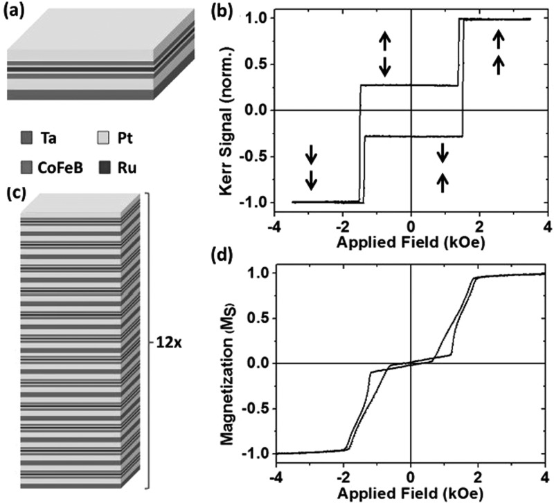
(a) The single coupled bilayer motif. (b) Polar MOKE hysteresis loop of the single bilayer. The arrows show the magnetization direction of each CoFeB layer perpendicular to the plane of the film. (c) The multilayer stack used to create the magnetic particles, where the basic motif is stacked 12 times. (d) VSM easy axis hysteresis loop of the 12 repeat motif multilayer stack.
Perpendicularly magnetized layers have become an important area of research in magnetic materials because they offer large data retention times and fast domain wall speeds21 for data storage applications22 as well as the possibility of novel logic applications through interacting multilayers via RKKY interactions.23 We demonstrate that in a SAF architecture they fulfil the key criteria desired here with a significant degree of control and flexibility in the engineered magnetic parameters. The motif of the magnetic multilayer stack used here is shown in Figure 2(a) and consists of Ta(2)/Pt(2)/CoFeB(0.9)/Pt(0.25)/Ru(0.9)/Pt(0.25)/CoFeB(0.9)/Pt(2), with thicknesses in nm. We show the polar magneto-optical Kerr effect (MOKE) hysteresis loop of a single bilayer building block in Figure 2(b), with the arrows representing the magnetization directions of the layers. This can be seen to be similar to the ideal hysteresis loop in Figure 1. The apparent non zero magnetization at remanence is due to the depth dependence of the MOKE signal. The RKKY coupling gives an antiparallel state at low magnetic field, with zero susceptibility. The thickness of the Ru interlayer lies at the first antiferromagnetic coupling peak.24 The switch to full magnetization occurs abruptly at a field which can be controlled by tuning the interlayer exchange coupling between the CoFeB layers via the Pt layer thickness on either side of the Ru layer.25 This effectively tunes the width of the low field antiparallel region; the higher the antiferromagnetic RKKY coupling, the higher the HSW. The SAF is also characterized by high out of plane anisotropy, and hence an easy axis of magnetization.
For applications which rely on the transduction of a mechanical force via the particles in an applied field, maximizing the magnetic moment of the particles is important. Figure 2(a) schematically shows how the moment is increased by stacking multiple repeats of this bilayer building block on top of each other. A vibrating sample magnetometry (VSM) hysteresis loop of the 12 times repeated bilayer is shown in Figure 2(c). The Ta(2)/Pt(2) buffer layers are included for each repeated bilayer system and are crucial in decoupling consecutive blocks, and therefore obtaining a field response in the 12 times repeated thin film that is similar to a single building block. The amorphous Ta layers in the buffer also act to break up the microstructure of the layers in an effort to minimize the degeneration of growth properties higher up the stack as has been seen elsewhere in similar multilayer coupled systems.28 Since each bilayer system is nominally identical, the stack as a whole shows a field response similar to a single bilayer. Increasing the number of building blocks does not lead to a degradation in the saturation magnetization or a significant change in the anisotropy of the layers. The switch to saturation also occurs by a more slanted transition. The average magnitude of RKKY coupling, measured by the interlayer coupling field which was taken to be the middle point of the transition of a minor loop measurement,25 shows a slight reduction due to growth inhomogeneities over the height of the 12 times repeated structure. This is likely to be due to a combination of the slight variation in RKKY coupling averaged over the 12 bilayer blocks and the switching being characterized by the formation of multidomain states driven by interlayer dipole fields during the switching process.26,27 A small spread in RKKY coupling strength and coercivity over the lateral extent of the thin film is also to be expected. The multilayer stack was grown on a 5 nm Au underlayer and was capped with the same to demonstrate the possibility of biological or surface functionalization to sterically hinder particle agglomeration via any non-magnetic effects such as Van der Waals interactions.
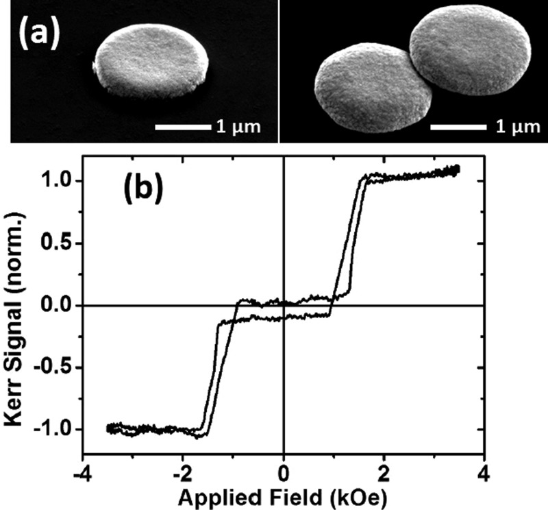
The perpendicularly magnetized RKKY coupled thin film has been shown to closely approximate the ideal properties we would require of a magnetic particle. However, the lithography process must ensure a successful transfer of these properties from the thin film to the particle. The sputtering of the multilayer thin film stack shown in Figure 2(a) was carried out on silicon substrates with pre-patterned pillars of photoresist. The multilayer stack grown on top of the resist pillars was then lifted off into solution by dissolving the resist pillars in acetone. The particles used here are 2 μm across made using optical lithography. SEM images of particles made from the 12 times stacked bilayer building block are shown in Figure 3(a). These are particles which have been lifted off into solution and then recondensed onto a substrate. Figure 3(b) shows the polar MOKE loop of a single such particle. The magnetic response of the particle is very similar to that of the nominally identical thin film.
FIG. 3.
(a) SEM images of 2 μm particles lifted off in solution and subsequently recondensed on a substrate. (b) Polar MOKE hysteresis loop of a single particle such as the one shown in (a).
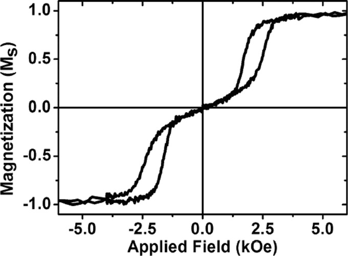
We also used a VSM to characterise the magnetic properties of these perpendicular SAF particles suspended in water in order to observe the effect of the particles being free to rotate in a fluid as opposed to being fixed to a substrate. Figure 4 shows that similar to the thin film, we see a zero net remanence in the fluid suspension with a distinct switch to saturation, which may be broadened due to a spread in properties in the particle ensemble. Significantly, the low field susceptibility, indicated by the linear magnetization response for fields below the switching field in Figure 4, is higher than the easy axis low field susceptibility of the thin film or the individual particle.
FIG. 4.
VSM Hysteresis loop of particles in water.
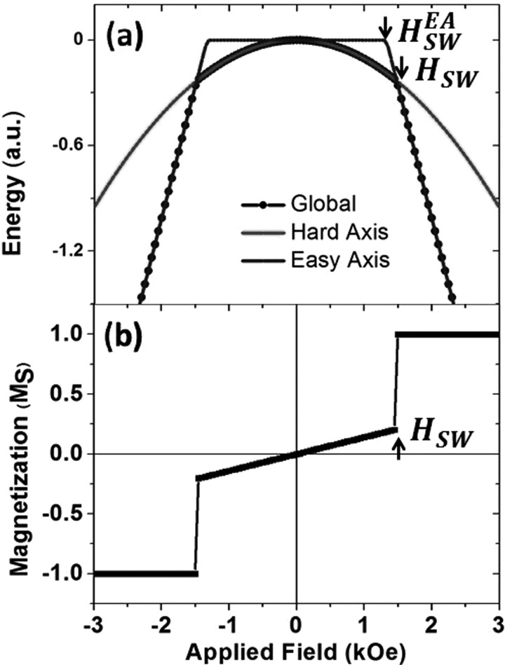
To further investigate this increased low field susceptibility, we conducted simulations of the minimum energy state for an RKKY coupled SAF bilayer system that is free to rotate in an applied field. In Figure 5(a), we show the minimized energy (black dots), the energy of the easy axis switching process (blue line), and the energy of the hard axis saturation process via the canting of antiferromagnetically coupled layers along the hard axis direction29 (red line) (see supplementary material for more information).30 Figure 5(a) shows that for fields below HSW, the bilayer system will be aligned with its hard axis in the field direction, and for fields above HSW with its easy axis in the field direction. The competition between these two processes means that the switch to saturation occurs at a higher field than in the easy axis process shown by . The magnetization in Figure 5(b) is obtained from the energy minimization and we observe the linear hard axis susceptibility below HSW, followed by a sharp transition to saturation, which must be accompanied by a rotation of the bilayer system. We see these characteristics in the magnetization curve in Figure 4 and attribute a similar behaviour to the SAF magnetic particles used here in response to an applied field. This result may be of relevance to magnetorheological fluids where the orientation of the particles in the fluid under an applied field can change the fluid viscosity.31 We ascribe the existence of the increased hysteresis in the magnetization curve of the particle suspension to be due to the particle being pinned in a metastable energy minimum caused by the competition between the easy and hard axis processes. Crucially, we demonstrate here that the relevant low field susceptibility of these perpendicularly magnetized SAF particles in a fluid is that of the hard axis, which in this high anisotropy thin film stack, has a saturation field of 7.2 kOe. This is significantly smaller low field susceptibility than vortex based SAF particles where the low field susceptibility is that of the easy magnetization axis and corresponds to shifting the vortex core.
FIG. 5.
(a) The global minimum energy of a perpendicular SAF bilayer with the energy of the magnetization processes along the easy and hard axes. (b) Simulated M-H loop for a perpendicular SAF bilayer.
The flexibility of this design is apparent. It is possible to tune the CoFeB layer thickness and hence the magnetic anisotropy, the HSW via the RKKY coupling strength, and the total magnetic moment via the number of repeats of the motif. We can thus tailor these particles to the required application and whilst we have shown results for 2 μm particles, a reduction in size can be achieved via alternative patterning techniques such as electron beam or nanoimprint lithography. The magnetic behavior of an individual perpendicular SAF particle is dominated by interfacial magneto-crystalline and RKYY terms. Hence, particle width has only minor effects on the magnetic properties of an individual particle since the behavior of perpendicularly magnetized layers is expected to be fairly constant down to around 40 nm at which their reversal is no longer dominated by domain wall movement.32 However, dipolar interactions between layers will increase with size reduction. In perpendicular materials dipolar interactions between two vertically stacked layers are ferromagnetic. This will weaken the AF coupling within each bilayer building block and lower HSW. Simulations show that for the stack used here, the stray field from one particle onto another adjacent particle, or from one magnetic layer on the other within the same bilayer block, is less than 200 Oe, well below HSW. We therefore expect a stable magnetic particle suspension under size reduction with regards to maintaining SAF behaviour within a single magnetic particle, as well as minimizing agglomeration between particles. Hence, perpendicular SAF particles provide a robust system with regards to maintaining key properties under size reduction.
In conclusion, perpendicularly magnetized films with RKKY coupling form a suitable basis for creating magnetic particles for the biological applications. We have demonstrated that the behavior of thin films can be transferred to particles in solution. We show that the perpendicularly magnetized SAF particles in a liquid are characterized by zero remanence, a low field susceptibility equal to their hard axis susceptibility, and a distinct switch to full magnetization. These particles have the advantage of precise tunability of a number of key parameters making them ideal for tailoring to specific applications. This result should allow a new generation of targeted magnetic particles to be developed, enhancing their numerous biotechnological applications.
Acknowledgments
This research was funded by the European Community under the Seventh Framework Program ERC Contract No. 247368: 3SPIN, NIH Grant No. R01NS077388 “Magnetic Vortex Microdiscs for Glioma Therapy” and the EPSRC Cambridge NanoDTC, Grant No. EP/G037221/1.
References
- 1. Pankhurst Q. A., Thanh N. T. K., Jones S. K., and Dobson J., J. Phys. D: Appl. Phys. 42, 224001 (2009). 10.1088/0022-3727/42/22/224001 [DOI] [Google Scholar]
- 2. Kim D.-H., Rozhkova E. A., Ulasov I. V., Bader S. D., Rajh T., Lesniak M. S., and Novosad V., Nat. Mater. 9, 165 (2010). 10.1038/nmat2591 [DOI] [PMC free article] [PubMed] [Google Scholar]
- 3. Domenech M., Marrero-Berrios I., Torres-Lugo M., and Rinaldi C., ACS Nano 7, 5091 (2013). 10.1021/nn4007048 [DOI] [PubMed] [Google Scholar]
- 4. Kashevsky B. E., Kashevsky S. B., Korenkov V. S., Istomin Y. P., Terpinskaya T. I., and Ulashchik V. S., J. Magn. Magn. Mater. 380, 335 (2015). 10.1016/j.jmmm.2014.10.109 [DOI] [Google Scholar]
- 5. Liu C., Stekenborg T., Peeters S., and Lagae L., Appl. Phys. Lett. 105, 102014 (2009). [Google Scholar]
- 6. Osman O., Toru S., Dumas-Bouchiat F., Dempsey N. M., Haddour N., Zanini L.-F., Buret F., Reyne G., and Frénéa-Robin M., Biomicrofluidics 7, 054115 (2013). 10.1063/1.4825395 [DOI] [PMC free article] [PubMed] [Google Scholar]
- 7. Neuberger T., Schpf B., Hofmann H., Hofmann M., and von Rechenberg B., J. Magn. Magn. Mater. 293, 483 (2005). 10.1016/j.jmmm.2005.01.064 [DOI] [Google Scholar]
- 8. Peter J. F. and Otto A. M., Proteomics 10, 628 (2010). 10.1002/pmic.200900535 [DOI] [PubMed] [Google Scholar]
- 9. Wang N., Butler J. P., and Ingber D. E., Science 260, 1124 (1993). 10.1126/science.7684161 [DOI] [PubMed] [Google Scholar]
- 10. Dobson J., Nat. Nanotechnol. 3, 139 (2008). 10.1038/nnano.2008.39 [DOI] [PubMed] [Google Scholar]
- 11. McBain S. C., Yiu H. P. H., and Dobson J., Int. J. Nanomed. 3, 169 (2008). [DOI] [PMC free article] [PubMed] [Google Scholar]
- 12. Wilson M. W., Kerlan R. K., and Fidleman N. A., Radiology 230, 287 (2004). 10.1148/radiol.2301021493 [DOI] [PubMed] [Google Scholar]
- 13. Leulmi S., Joisten H., Dietsch T., Iss C., Morcrette M., Auffret S., Sabon P., and Dieny B., Appl. Phys. Lett. 103, 132412 (2013). 10.1063/1.4821854 [DOI] [Google Scholar]
- 14. Joisten H., Courcier T., Balint P., Sabon P., Faure-Vincent J., Auffret S., and Dieny B., Appl. Phys. Lett. 97, 253112 (2010). 10.1063/1.3518702 [DOI] [Google Scholar]
- 15. Silva A. C., Oliveira T. R., Mamani J. B., Malheiros S. M. F., Malavolta L., Pavon L. F., Sibov T. T., E. Amaro, Jr. , Tannús A., Vidoto E. L. G., Martins M. J., Santos R. S., and Gamarra L. F., Int. J. Nanomed. 6, 591 (2011). [DOI] [PMC free article] [PubMed] [Google Scholar]
- 16. Fortin J.-P., Wilhelm C., Servais J., Ménager C., Bacri J.-C., and Gazeau F., J. Am. Chem. Soc. 129, 2628 (2007). 10.1021/ja067457e [DOI] [PubMed] [Google Scholar]
- 17. Vitol E. A., Novosad V., and Rozhkova E. A., Nanomedicine 7(10), 1611 (2012). 10.2217/nnm.12.133 [DOI] [PMC free article] [PubMed] [Google Scholar]
- 18. Slade R. A., Evans J. S. O., Parker D., Cowburn R. P., and Eaton M., U.S. patent 20090306455 A1 (10 December 2009).
- 19. Cowburn R. P., Koltsov D. K., Adeyeye A. O., Welland M. E., and Tricker D. M., Phys. Rev. Lett. 83, 1042 (1999). 10.1103/PhysRevLett.83.1042 [DOI] [Google Scholar]
- 20. Hu W., Wilson R. J., Koh A., Fu A., Faranesh A. Z., Earhart C. M., Osterfeld S. J., Han S. J., Xu L., Guccione S., Sinclair R., and Wang S. X., Adv. Mater. 20, 1479 (2008). 10.1002/adma.200703077 [DOI] [Google Scholar]
- 21. Moore T. A., Miron I. M., Gaudin G., Serret G., Auffret S., Rodmacq B., Schuhl A., Pizzini S., Vogel J., and Bonfim M., Appl. Phys. Lett. 93, 262504 (2008). 10.1063/1.3062855 [DOI] [Google Scholar]
- 22. Kim K.-J., Lee J.-C., Yun S.-J., Gim G.-H., Lee K.-S., Choe S.-B., and Shin K.-H., Appl. Phys. Express 3, 083001 (2010). 10.1143/APEX.3.083001 [DOI] [Google Scholar]
- 23. Lavrijsen R., Lee J.-H., Fernández-Pacheco A., Petit D., Mansell R., and Cowburn R. P., Nature 493, 647 (2013). 10.1038/nature11733 [DOI] [PubMed] [Google Scholar]
- 24. Bruno P. and Chappert C., Phys. Rev. B 46, 261 (1992). 10.1103/PhysRevB.46.261 [DOI] [PubMed] [Google Scholar]
- 25. Lavrijsen R., Fernández-Pacheco A., Petit D., Mansell R., Lee J. H., and Cowburn R. P., Appl. Phys. Lett. 100, 052411 (2012). 10.1063/1.3682103 [DOI] [Google Scholar]
- 26. Moritz J., Garcia F., Toussaint J. C., Dieny B., and Nozires J. P., Europhys. Lett. 65, 123 (2004). 10.1209/epl/i2003-10063-9 [DOI] [Google Scholar]
- 27. Hellwig O., Berger A., Kortright J. B., and Fullerton E. E., J. Magn. Magn. Mater. 319, 13 (2007). 10.1016/j.jmmm.2007.04.035 [DOI] [Google Scholar]
- 28. Lee J.-H., Mansell R., Petit D., Fernández-Pacheco A., Lavrijsen R., and Cowburn R. P., SPIN 3, 1340013 (2013). 10.1142/S2010324713400134 [DOI] [Google Scholar]
- 29. Zhu J.-G., IEEE Trans. Magn. 35, 655 (1999). 10.1109/20.750623 [DOI] [Google Scholar]
- 30.See supplementary material at http://dx.doi.org/10.1063/1.4926336E-APPLAB-107-056527 for details on the simulation of a SAF bilayer system that is free to rotate in an applied field.
- 31. Bossis G., Lacis S., Meunier A., and Volkova O., J. Magn. Magn. Mater. 252, 224 (2002). 10.1016/S0304-8853(02)00680-7 [DOI] [Google Scholar]
- 32. Gajek M., Nowak J. J., Sun J. Z., Trouilloud P. L., O'Sullivan E. J., Abraham D. W., Gaidis M. C., Hu G., Brown S., Zhu Y., Robertazzi R. P., Gallagher W. J., and Worledge D. C., Appl. Phys. Lett. 100, 132408 (2012). 10.1063/1.3694270 [DOI] [Google Scholar]
Associated Data
This section collects any data citations, data availability statements, or supplementary materials included in this article.
Data Citations
- See supplementary material at http://dx.doi.org/10.1063/1.4926336E-APPLAB-107-056527 for details on the simulation of a SAF bilayer system that is free to rotate in an applied field.


