Abstract
In this paper we discuss two possible strategies of movement control that can be used by stroke survivors during rehabilitation robotics training. To perform a reaching task in a minimally assistive force field, subjects either can move following the trajectory provided by the assistive force or they can use an internal representation of a minimum jerk trajectory from their starting position to the target. We used the stiffness and damping values directly estimated from the experimental data to simulate the trajectories that result by taking into account both hypotheses. The comparison of the simulated results with the data collected on four hemiparetic subjects supports the hypothesis that the central nervous system (CNS) is still able to correctly plan the movement, although a normal execution is impaired.
I. Introduction
When unimpaired individuals reach for an object in the Cartesian space their hand follows an approximately straight line trajectory with a bell-shaped velocity profile [1]. Flash and Hogan demonstrated that the trajectory has a minimum jerk time-profile [2]
When a reaching movement is performed within a force field the trajectory is perturbed. Subjects adapt to this force field by building an internal model [3] and counteracting in real-time the perturbing force with a model-driven force of equal amplitude and opposite direction. More specifically, for each movement repetition subjects tend to restore the original trajectory, which is used as a reference state for the stiffness and damping to correct the actual trajectory from the deviations caused by the perturbations.
In this study we consider the case where stroke survivors performed the movements with their impaired limb within a dynamic environment where a robot provides an assistive force field, pointing at the designated target. Stroke survivors are often affected by limb dyscoordination, characterized by muscle weakness and stereotypical joint couplings. Dyscoordination impairs the execution of movements and breaks down the reaching action into a series of sub-actions, thus losing the optimal features of minimum jerk (MJ) trajectories [4].
Rehabilitation robotics is used to improve the mobility and upper limb range of motion in stroke survivors. Robots are programmed to help subjects execute a series of movement sequences, aiming to disrupt the pathological joints' coupling via appropriate assistive force fields. Although the process of functional recovery is still largely unknown we can formulate the hypothesis that it may consist, from the computational point of view, in the re- development of an internal trajectory model, to be used as a reference for online corrections by means of arm stiffness and damping. We tested this hypothesis by comparing two alternative learning mechanisms that could be used by the CNS for building this reference trajectory after a stroke: 1) complying with the force profile to obtain a minimum effort trajectory in order to reach the target. In this view, the rehabilitative task can produce adaptation to the assistive force because the subjects, instead of resisting the force field, exploit it to reach the target with a minimal resistance; 2) some studies suggested [5], based on the assumption that in stroke survivors the ability to plan movements “in one shot” remains intact but the motor plan cannot be released, that the reference trajectory used to correct the movement would have MJ characteristics, and the role of the assistive force would be simply to facilitate the release of the motor plan.
To clarify what strategy is more likely used by the CNS after a stroke we simulated the trajectories that would result according to both of these hypotheses and we compared them with experimental data. In the model simulation we used stiffness and damping values directly estimated from the data. Although a full generalization should be made with caution due to the limited amount of subjects, our results suggest that subjects still maintain an MJ trajectory as a motor plan. This work provides a better understanding of mechanisms inherent to robot mediated stroke rehabilitation and therefore can help develop specific robotic exercises to improve recovery after stroke.
II. Methods
A. Robot Mediated exercise
Four chronic stroke survivors with different levels of impairment participated in the experiment and their clinical and anthropometric data are listed in Tab.I. Subjects held with their right impaired hand the end-effector of a planar manipulandum [6]. Their shoulders and wrist movements were restricted by using custom made holders.
Table I. Subject Characteristics.
| Age | FM before | FM after | Ash | G | E | WT | HT | Fa | |
|---|---|---|---|---|---|---|---|---|---|
| P1 | 53 | 41 | 45 | 1 | F | H | 58 | 1.68 | 5 |
| P2 | 59 | 5 | 8 | 3 | F | I | 65 | 1.70 | 20 |
| P3 | 69 | 12 | 18 | 1+ | F | I | 60 | 1.55 | 12 |
| P4 | 34 | 13 | 23 | 1+ | F | I | 67 | 1.78 | 9 |
Subjects data. Age: years. FM = upper arm Fugl- Meyer score, max 66/66; before, after and after three months with respect to the robot therapy sessions, Ash= Ashworth score, Gender: M=male, F=female; E= Etiology: I=ischemic, H= Hemorrhagic; WT=weight [kg]: HT=Height [m]; Fa=level of assistive force at which we estimated the stiffness [N]
The task depicted in Fig.(1) was to hit a set of 7 equally spaced targets arranged at distal positions almost to the workspace limit (C layer). The exercise was composed of blocks where subjects stating from the 3 different positions (A Layer) had to reach each of the 7 targets, presented in random order. Each block consisted of 21 outward movements of amplitude about 20 cm. The workspace was centered with respect to the right shoulder joint.
Fig. 1.
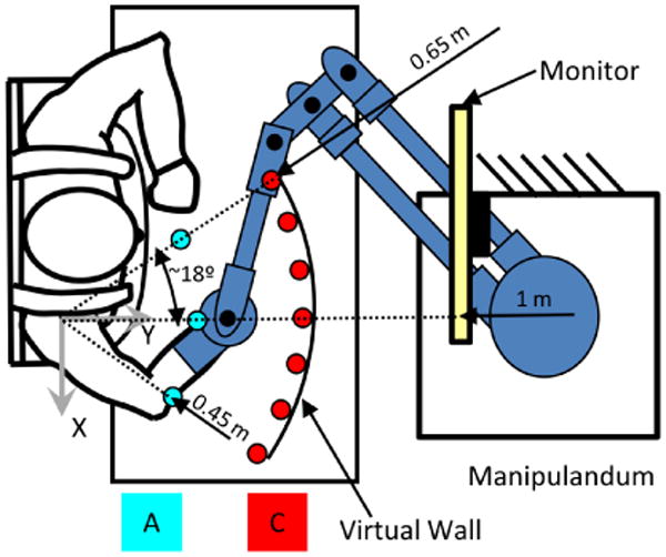
Experimental setup. A represent the starting point layer, C represents the targets layer. All combinations of targets was performed for a total of 3×7=21 reaches per session
The planar robotic manipulandum provided assistive forces helping stoke survivors to accomplish the task. Subjects saw their arm, the robot, and a computer monitor (1 meter away at eye level) that displayed the end-effector position and the target to reach (Fig. 1). The target and the cursor corresponding to the end-effector position were represented as round disks of different colors and 1 cm radius. The haptic rendering of the environment was generated according to the equation:
| (1) |
where terms in bold (e.g u ) represent vectors and terms in italic (e.g u ) represent scalars. In Eq.(1) Fe is the force provided by the manipulandum, xT is the target position, xe is the position of the end-effector, Fa is the selected level of the assistive force in the trial (see Tab. I). The term G(Fa, t) starts from 0, increasing linearly to Fa with a rise time of 1s; therefore, enabling a smooth activation of the force field. The two additional terms represent a viscous field to stabilize the arm posture and a rigid wall. While the viscous field is always active, the rigid wall engages only beyond the targets' level, which provided a representation of the boundary of the workspace. The coefficient Be was empirically determined to be 12Ns/m as a trade-off between stability and dissipated energy, while the stiff virtual wall was rendered with a 1000 N/m elastic coefficient Kw [7]. The training consisted of 10 sessions of a duration that ranged from 45 to 75 minutes. Each session started with the same initial force, selected by the therapist as the minimal force allowing the subject to initiate the movement. After the first two blocks, the therapist could decide to extend the exercise with additional blocks. In these blocks, the levels of force were lowered, in accordance with the subject's residual ability and fatigue. For each subsequent session, while starting always with the first imposed force of the first session, subjects experienced a further decrease of assistive force, where the ultimate goal would be (when possible) to reach the target with no assistive force. When subjects reached each target, the assistive force and visual feedback were switched off for 1s before the following target appeared on the screen. The kinematic response to this sudden drop in assistive force was used to estimate the arm impedance using the time frequency technique described in [8-11].
B. Rigidity and Viscosity vs Stiffness and Damping
One of the consequences of stroke is the development of an intrinsic arm rigidity that might result in a dominant flexion pattern. Such rigidity generates a position dependent force that can vary with the degree of impairment, with values up to 8 Nm/rad [12]. Rigidity is relative to the starting point of the trajectory and not to the trajectory itself. Indeed, by applying a displacement to the hand, in the direction away from the body, there is a roughly linear increase in force opposing the movement. In this work we will refer to this phenomenon as “rigidity”. Conversely, we will apply the term “stiffness” to the parameter that generates a position dependent reaction force when a deviation of the arm from the intended trajectory occurs. Rigidity and stiffness have two different reference points. During a point-to-point movement, rigidity generates a force field that tends to bring the arm back to the starting point, hence hindering the movement. Stiffness generates a position dependent force field that aims to bring the arm back to the intended trajectory if a disturbance occurs. The stiffness reference point changes in time, moving synchronously with the intended trajectory. In general, stiffness is one order of magnitude larger than rigidity. However, the force that they can generate at the end-effector can be comparable since the rigidity is multiplied by the amplitude of the movement, while stiffness is multiplied by the deviation of the movement from the intended trajectory.
Similar considerations can be made for Viscosity and Damping. The former is similar to rigidity and generates a force field proportional to the instantaneous velocity of the movement. The latter generates a force field proportional to the rate of change of the real trajectory with respect to the intended one. A simple schematic of the coupling between robot and human arm mechanics in the Cartesian space for a single degree of freedom is depicted in Fig.(2). The arrangement of inertia M, stiffness K, damping C, rigidity R, and viscosity D can be observed. The system is governed by the following equation.
Fig. 2.
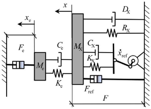
Mechanical schematics of the interaction between the human arm and the robot:[Mx,Cx,Kx] and [Me,Be,Ke] are the inertia, damping, and stiffness of the arm and the environment, respectively. Fe is the assistive force, Fref and vref are the reference force and velocity for the subject motor plan. [Rx,Dx] are the rigidity and viscosity of the arm
| (2) |
Subscript e refers to the environment created by the robot, while subscript X refers to the properties of the arm in the Cartesian space. Variables xi and xei are the ith coordinate of the hand and robot's end-effector, respectively. Fei is the force provided by the manipulandum from Eq.(1), Frefi and ẋrefi are the reference force and velocity for the subject motor plan.
C. Main hypotheses and relative assumptions
The main assumption of this work is that subjects are able to plan a reference trajectory to correct their movements using the limb's stiffness and damping. We performed a set of simulations to verify if the reference trajectory used by the subjects is either the trajectory generated by the assistive force on their passive mechanics, or a straight minimum jerk trajectory (typical of unimpaired individuals).
The reference trajectory based on external force (EF) can be calculated solving the Eq.(2) for all degrees of freedom (DOF) assuming Cx,e = Kx,e = 0, while imposing, Rx, Dx , and Fe. Notice that Be is embedded in Fe and it depends on the velocity of the end-effector. Since the arm is modeled as a double pendulum and not as a point mass, the inertial matrix Mx is not diagonal. Hence, the EF trajectory is not a straight line due to the effect of centripetal and Coriolis force about the joints. The trajectory is curved but it is the most advantageous to reach the target in terms of minimum modulation of joint torque. The solution of Eq.(2) given the aforementioned constraints will be used as reference trajectory so that xEF = xref.
On the other hand, the use of a minimum jerk (MJ) reference trajectory would aim to minimize the distance between the starting point and the target (i.e. a straight line in x and y)
To calculate the possible MJ reference trajectory we used the following equation:
| (3) |
where xrefi is a co-ordinate in the Cartesian space so that, xref1 = x, xref2 = y; T is the duration of the movement; ai0 = xrefi(0), ai1 = ẋrefi(0), , and the other coefficients can be calculate as follows:
| (4) |
From the experimental data, we obtained the reaching time T of each assisted movement. The time was estimated as the period comprised between the instant in which subjects increase the hand absolute reaching velocity above 10% of the absolute maximum to the instant in which they decrease the velocity below such threshold, permanently. No assumption on the arm model is necessary.
Conversely, to estimate the EF trajectory requires some assumption of limb mechanics. The arm was modeled as a two DOF system where the shoulder has a fixed center of rotation. Arm inertial parameters where estimated based on a subject's weight and height [13]. The efficacy of this method with respect to others is described in [14]. The implemented rigidity and viscosity were estimated using an algorithm described in the next section. Hence, the trajectory of the hand in the Cartesian space was computed using an inverse dynamic routine implemented in Simulink®. The assistive force was implemented as described in Eq. (1)
D. Rigidity estimation
Given the desired reaching time of the movement and the external force applied in the experiment, we implemented a first simulation to find the maximum allowed rigidity. Setting the reference position for the rigidity at the starting point, the farther from such position the hand is displaced, the larger the force generated by the rigidity.
Setting Cx = Kx = 0, and the external force Fe, we will iteratively change the rigidity and viscosity so that the hand would reach the target at the same time T of the real trajectory. Since the assistive force is switched off when the target is reached, if the set rigidity is too low, then the movement will be too fast, and a recoil will be present. Conversely, if the resistive force generated by the rigidity is too high, the end-effector would not reach the target in the desired time.
We set the starting rigidity and viscosity matrices at the joints to
| (5) |
which is approximately the normal joint “rigidity” of an unimpaired individual, with no load applied [15]. The index 1 refers to the shoulder, 2 refers to the elbow. Since rigidity and viscosity of stroke survivors are going to be higher than such values, we considered a multiplicative coefficient of “rigidity” ρ > 1 to account for the impairment and modulate the resistive torque as follows:
The parameter ρ was changed in our simulations so to obtain a trajectory that given the assistive force Fe and reaching time T, the subjects hand would reach the target on time and with no residual recoil. In this work, the maximum value of the coefficient of “rigidity” was 2, producing a maximum rigidity of 7 Nm/rad, well within the mentioned physiological range [12].
E. Joint stiffness estimation
The endpoint stiffness KX, and damping CX, were measured using a newly developed technique, which can estimate the parameters from the values of the arm residual vibration after the target is reached and the assistive force is suddenly switched off. The description of the technique can be found in [10, 11], while experimental results used in the present paper are reported in [8, 9]. Generally, during postural conditions with no external force applied to the hand, stiffness magnitude and orientation are position dependent. However, it was shown that within a force field arm stiffness is tuned in the direction of the force [16, 17]. This effect was also found for the distribution of stiffness and damping during this robot mediated task [8], where the orientation of stiffness is aligned with the assistive force and the magnitude is proportional to it (which after the transient ramp is the same across the whole workspace). Given the similarities of endpoint stiffness and damping across the reachable workspace, we assumed them to be constant along the direction of movements. Hence, the transformation to the joint space provides:
| (6) |
Where Fe is the force vector in Eq.(1), and JT(θ) is the transposed Jacobian matrix between the Cartesian and the joint space. Notice that J is a function of the joint angles' vector and anthropometry of each subject.
F. Forward simulations
After estimating the two reference trajectories (EF, MJ), the former by finding the optimal joint rigidity and viscosity (Rθ, Dθ), we could use the experimentally estimated stiffness and damping (Kθ, Cθ) [8, 9] to simulate the chosen control strategies, where either of these trajectories is used as reference.
We compared the resulting task trajectories using the cross-correlation function between the velocity time profile of the data and the velocity signals of the simulations.
| (7) |
The correlation coefficients are the values of the cross-correlation function when the lag τ = 0.
The coefficients where statistically analyzed using repeated measure analysis of variance (ANOVA) with three fixed factors: methods, direction of movement, and sessions, and subject as a random factor.
Furthermore, while the experiment consisted of 10 sessions, the initial sessions are quite difficult to investigate using the proposed approach, since subjects' movements were quite segmented and at very low speed. Hence, we performed the proposed comparison starting from the 4th session, to the 10th, where speed and timing were compatible with single movement trajectories.
Finally, to highlight the importance of knowing the exact stiffness and damping the same simulation where repeated using (Kθ, Cθ), proper of an unimpaired individual [11]:
| (8) |
both constant throughout the movement.
III. Results
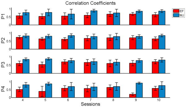
Figure (3) shows for each subject the correlation coefficients ℜdata,MJ (0), and ℜdata,EF (0) as a function of the rehabilitative sessions. The statistical analysis reported in Tab. (II) confirmed that ℜdata,MJ (0) is significantly higher than ℜdata,EF (0) (0.80 vs 0.61) suggesting that using a MJ trajectory as a reference for the stiffness and damping is the strategy that best fits the data in this example.
Fig. 3.
Correlation coefficients between experimental data and simulations as a function of the training session.
Table II. Three Way Anova with Subject as a Random Factor.
| source | df | ℜdata,MJ(0) vs ℜdata,EF(0) | |
|---|---|---|---|
| F(1,df) | p | ||
| Session | 5 | 0.94 | 0.48 |
| Direction | 5 | 3.77 | 0.02 |
| Method | 1 | 44.20 | 0.01 |
| Session * Direction | 35 | 2.16 | <0.0001 |
| Session * Method | 6 | 13.74 | <0.0001 |
| Method * Direction | 6 | 10.73 | <0.0001 |
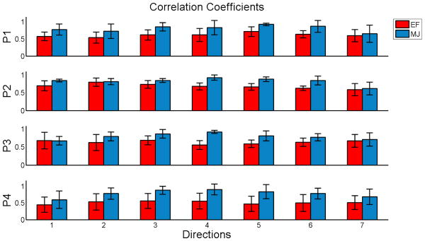
Tab. (II) also shows that the correlation depends on the movement direction (significant effect of direction and interaction between method and direction). Figure (4) shows the correlation coefficients as functions of the direction of movement. Such dependencies on the direction might find a justification in the physical constraint of the arm's passive mechanics (inertia, rigidity, and viscosity).
Fig. 4.
Correlation coefficients between experimental data and simulations as function of the movement direction.
The effect of training (session) is not significant while the interactive terms session*method and session*direction are significant. Indeed, training induces an improvement in performance that decreases the errors in the direction with the highest degree of impairment. As a consequence, it determines an improvement of correlation with the MJ, but not with the EF method. A multi-factorial analysis for each coefficient ℜdata,sim(0) with subject as a random factor is reported in Tab.(III). While the coefficients do not depend statistically upon sessions, there is a dependence of ℜdata,MJ(0) upon the direction of movement and an interactive session*direction.
Table III. Two Way Anova with Subject as a Random Factor Among All Sessions and Directions.
| source | df | ℜdata,EF(0) | ℜdata,MJ(0) | ||
|---|---|---|---|---|---|
| F(1,df) | p | F(1,df) | p | ||
| Session | 5 | 1.25 | 0.33 | 1.90 | 0.1435 |
| Direction | 5 | 0.55 | 0.74 | 7.75 | 0.0005 |
| Session * Direction | 35 | 1.25 | 0.16 | 2.07 | 0.0004 |
Finally, we can see in Fig.(5C) that for the contralateral side (left on the figure), the introduction of the measured stiffness and damping changes the curvature of the movement both for EF and MJ reference trajectories presented in Fig.(5A). This effect is much milder using the idealized stiffness in Eq.(8) of an intact individual as shown in Fig.(5B). This Supports the hypothesis that stroke survivors can still produce a motor plan similar to unimpaired individuals; however, the final trajectory is conditioned by the abnormal stiffness and damping.
Fig. 5.
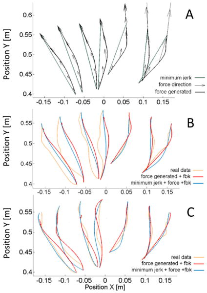
A) reference trajectories calculated for a representative subject. MJ trajectories are straight lines wile EF are curved laterally. The direction of the force vector that generated EF is also reported. B) a comparison between experimentally obtained and simulated trajectories using either EF or MJ as a reference. Fe is applied at the hand and feedback (fbk) is generated by the stiffness and damping of an unimpaired individual (see Eq.(8)). C) Same as B where the experimentally measured stiffness and damping are used. The introduction of proper feedback can change the trajectories' curvature.
IV. Discussion
In this work we tested the hypothesis that during robot mediated therapy stroke survivors maintain an unaltered motor plan, where a MJ trajectory is used as a reference for the correction of the movement by means of stiffness and damping. The alternative hypothesis encompassed the possibility of using the trajectory generated by the assistive force on the passive mechanics (inertia, rigidity and viscosity) as reference. The results support the first hypothesis.
We developed a method to account for the limb rigidity and viscosity, based on a series of inverse dynamics simulations. While the simulations returned a result that was physiologically plausible, we acknowledge that for a multi-degrees of freedom model the rigidity matrix Rθ might not be symmetric. The asymmetry could have an effect on the final trajectory. However, the resulting trajectory obtained using MJ as a reference and combining measured stiffness and damping and simulated rigidity and viscosity, fits the experimentally observed trajectory well, as confirmed by the large correlation coefficients.
One of the disadvantages of using a MJ reference trajectory is the impossibility to impose a maximum velocity of the reach. Indeed, if higher than third order derivatives of position with respect to time were to be minimized (snap, crackle, and pop) the peak velocity would become larger than the one obtained by minimizing jerk. However, the resulting peak velocity of MJ is similar to the experimental data.
We also observed some biomechanical constrains that can cause the subject to use different strategies when interacting with an assistive force. The endpoint velocity of a right handed subject is higher when moving from the contralateral to the ipsilateral side (left to right), even though the external force and the movement distance are the same. This observation points out the possibility to chose different strategies when moving in different directions. One of the reasons for a subject to use a force generated trajectory lies on the out coming velocity profiles, which depends on the value of rigidity and viscosity. With a coefficient of rigidity so that the hand can reach the target, the peak velocity is larger than the experimental data. The introduction of stiffness and damping also increases the velocity profile. This aspect might induce the subject to favor the EF trajectory instead of a smother MJ trajectory.
Finally, we confirmed that knowing the real stiffness of the hand is important to properly model the movements of an impaired individual. While the motor planning seems to remain intact, the outcome result is strongly influenced by altered stiffness and damping values.
Acknowledgments
Authors would like to thanks Psiche Giannoni for her valuable contribution to this work.
This research was supported by NNINDS grant 2R01NS035673 and EU grant HUMOUR (FP7-ICT-231724).
Contributor Information
Davide Piovesan, Email: d-piovesan@northwestern.edu, Sensory Motor Performance Program at the Rehabilitation Institute of Chicago (SMPP-RIC), Chicago, IL 60611 USA (phone: 312-238-1225; fax: 312-238-2208).
Maura Casadio, Email: maura.casadio@unige.it, Dept of Informatics, Systems and Telematics, University of Genoa, Genoa, Italy.
Ferdinando A. Mussa-Ivaldi, Email: sandro@northwestern.edu, Rehabilitation Institute of Chicago, and the Department of Physiology Northwestern University Chicago, IL 60611 USA.
Pietro Morasso, Email: pietro.morasso@iit.it, Italian Institute of Technology, Dept. of Robotics, Brain and Cognitive Sciences, 16163 Genoa, Italy.
References
- 1.Morasso P. Spatial control of arm movements. Experimental Brain Research. 1981;42:223–227. doi: 10.1007/BF00236911. [DOI] [PubMed] [Google Scholar]
- 2.Flash T, Hogan N. The coordination of arm movements: An experimentally confirmed mathematical model. J Neurosc. 1985;5:1688–1703. doi: 10.1523/JNEUROSCI.05-07-01688.1985. [DOI] [PMC free article] [PubMed] [Google Scholar]
- 3.Shadmehr R, Mussa-Ivaldi FA. Adaptive representation of dynamics during learning of a motor task. J Neurosc. 1994;14:3208–3224. doi: 10.1523/JNEUROSCI.14-05-03208.1994. [DOI] [PMC free article] [PubMed] [Google Scholar]
- 4.Beer RF, Dewald JPA, Rymer WZ. Deficits in the coordination of multijoint arm movements in patients with hemiparesis: evidence for disturbed control of limb dynamics. Experimental Brain Research. 2000;131:305–319. doi: 10.1007/s002219900275. [DOI] [PubMed] [Google Scholar]
- 5.Beer R, Dewald J, Rymer Z. Chapter 42 Disturbances of Voluntary Movement Coordination in Stroke: Problems of Planning or Execution? In: Binder MD, editor. Progress in Brain Research. Vol. 123. Elsevier; 1999. pp. 455–460. [DOI] [PubMed] [Google Scholar]
- 6.Casadio M, Morasso PG, Sanguineti V, Arrichiello V. Braccio di Ferro: a new haptic workstation for neuromotor rehabilitation. Technol Health Care. 2006;13:1–20. [PubMed] [Google Scholar]
- 7.Casadio M, Morasso P, Sanguineti V, Giannoni P. Minimally assistive robot training for proprioception enhancement. Exp Brain Res. 2009 Apr;194:219–31. doi: 10.1007/s00221-008-1680-6. [DOI] [PubMed] [Google Scholar]
- 8.Piovesan D, Casadio M, Morasso P, Giannoni P. Influence of Visual Feedback in the Regulation of Arm Stiffness Following Stroke. (EMBS): Conference of the IEEE. 2011:8239–8242. doi: 10.1109/IEMBS.2011.6092031. [DOI] [PubMed] [Google Scholar]
- 9.Piovesan D, Casadio M, Mussa-Ivaldi FA, Morasso PG. Multijoint arm stiffness during movements following stroke: Implications for robot therapy. (ICORR), 2011 IEEE Conference. 2011:1–7. doi: 10.1109/ICORR.2011.5975372. June 29 2011-July 1 2011. [DOI] [PMC free article] [PubMed] [Google Scholar]
- 10.Piovesan D, Dizio P, Lackner JR. A new time-frequency approach to estimate single joint upper limb impedance. (EMBS): Conference of the IEEE. 2009;1:1282–5. doi: 10.1109/IEMBS.2009.5333242. [DOI] [PubMed] [Google Scholar]
- 11.Piovesan D, Pierobon A, DiZio P, Lackner JR. Measuring Multi-Joint Stiffness during Single Movements: Numerical Validation of a Novel Time-Frequency Approach. PLoS ONE. 2012;7:e33086. doi: 10.1371/journal.pone.0033086. [DOI] [PMC free article] [PubMed] [Google Scholar]
- 12.Schmit BD, Dhaher Y, Dewald JP, Rymer WZ. Reflex torque response to movement of the spastic elbow: theoretical analyses and implications for quantification of spasticity. Annals of biomedical engineering. 1999;27:815–29. doi: 10.1114/1.234. [DOI] [PubMed] [Google Scholar]
- 13.Zatsiorsky V, Seluyanov V. International Congress of Biomechanics: Biomechanics VIII-B. Champaign, Illinois: 1983. The mass and inertia characteristics of the main segments of the human body 30; pp. 1152–1159. [Google Scholar]
- 14.Piovesan D, Pierobon A, DiZio P, Lackner JR. Comparative Analysis of Methods for Estimating Arm Segment Parameters and Joint Torques From Inverse Dynamics. Journal of Biomechanical Engineering. 2011;133:031003. doi: 10.1115/1.4003308. [DOI] [PubMed] [Google Scholar]
- 15.Wiegner aW, Watts RL. Elastic properties of muscles measured at the elbow in man: I. Normal controls. Journal of neurology, neurosurgery, and psychiatry. 1986;49:1171–6. doi: 10.1136/jnnp.49.10.1171. [DOI] [PMC free article] [PubMed] [Google Scholar]
- 16.Darainy M, Malfait N, Gribble PL, Towhidkhah F, Ostry DJ. Learning to Control Arm Stiffness Under Static Conditions. Journal of Neurophysiology. 2004 Dec 1;92:3344–3350. doi: 10.1152/jn.00596.2004. 2004. [DOI] [PubMed] [Google Scholar]
- 17.Kolesnikov M, Piovesan D, Lynch K, Mussa-Ivaldi F. On Force Regulation Strategies in Predictable Environments. (EMBS): Conference of the IEEE. 2011;1:4076–4081. doi: 10.1109/IEMBS.2011.6091013. [DOI] [PMC free article] [PubMed] [Google Scholar]


