

Abstract
The purpose of this study was to evaluate and compare the effect of varying layers of two commercially available die spacers on pre-cementation space of full coverage restorations in vitro and in vivo. Seven dies were prepared for each of 15 subjects. On three dies 1, 2, 3 layers of Pico-fit and on other three dies 1, 2, 3 layers of Yeti die spacers applied, wax pattern fabricated, invested and cast. Metal copings seated in vitro on die without die spacer and on prepared tooth of respective subject with fit-checker. Thickness of fit checker was measured using micrometer at mid-axial, mid-occlusal and near finish line locations that provided pre-cementation space. Result of ANOVA tests suggested significant difference among groups with varying layers. There was no significant difference between pre-cementation space achieved with Pico-fit and Yeti die spacers. The r values suggested positive correlation between the respective pair of in vivo and in vitro groups. (1) There was significant difference between pre-cementation space at mid-axial and mid-occlusal sites achieved with 1, 2 and 3 layers of die spacers except between 1 and 2 layers and 1 and 3 layers at mid-occlusal site. (2) Pre-cementation space achieved with Pico-fit and Yeti die spacers did not differ significantly for same location, layers and in vitro and in vivo. (3) Pre-cementation space achieved in vitro was analogous to pre-cementation space achieved in vivo for respective location, layers and die spacer.
Keywords: Coping, Die spacer, Finish line, Pre-cementation space
Introduction
When restoring teeth with fixed prosthesis, it is crucial to gain original form and position with what can be called as ideal restoration. To fulfill the requirements for an ideal restoration, a casting must be made to fit the prepared tooth intimately [1]. The more precisely the casting fits the prepared tooth, the more difficult it is for cement between the casting and prepared tooth surface to escape. It causes incomplete seating of the casting and marginal opening. Ultimately the effects are creation of premature occlusal contacts, inappropriate proximal contacts, discrepancies of marginal fit of the casting and lack of comfort [2]. The fundamental reason for incomplete seating is lack of space for cement film. It leads to development of hydraulic pressure under the casting that increases until it matches seating force and causes further seating impossible [3].
There are basically two techniques to improve the seating of castings that relieves the hydraulic pressure established during cementation (1) venting of casting [3] and (2) internal relief in the casting. It is proved that venting improved the seating of crowns to a significant extent [2, 3]. But it is seldom used because an extra visit is required to seal the escape hole, material used to seal the escape hole may wear away and occlusal venting of ceramic or metal ceramic crowns may weaken the ceramic. Methods used to achieve internal relief include- mechanical grinding of the inner side of casting [4], carving of the wax pattern [4], aqua regia etching of casting [5], electrochemical milling [4], cutting an internal channel [6, 7] and most common, die spacing. Methods of mechanical grinding of casting and carving of wax pattern were rejected as they were inaccurate and inconsistent [4]. Aqua regia etching was considered effective but does not provide uniform relief [5]. Electrochemical milling process requires potassium cyanide which is hazardous and also impractical for relief of metal ceramic restorations [4]. Researchers have tried to obtain internal relief by cutting internal channels in prepared abutment teeth and/or in the internal surface of crowns before cementation [6, 7]. This has reduced the mean marginal discrepancy but causes loss of fit between the tooth and casting in discreet areas where channels are prepared.
Fusayama et al. [8] for the first time used manicure liquid as spacer on to the die. They studied the effect of the spacers on seating of casting. The positive results gave die spacer to the profession. Die spacing is achieved by painting the solution on to the die before fabrication of wax pattern. The use of die spacer is expected to provide uniform space for luting agent. These spaces improve the outflow of excess cement, decrease the seating forces, reduce the marginal discrepancy and improve occlusal contacts. Advantages of use of die spacer as compared to other methods includes- a simple technique for obtaining internal relief, when used appropriately gives uniform pre-cementation space/cement space. Various studies concluded that application of die spacer is an effective way of providing internal relief for the indirect restoration. Presently, use of die spacer for internal relief of casting is the most widely accepted method.
Optimum cement film thickness for maximum shear resistance between teeth and restoration should be 30 µ [9]. The American Dental Association specification No. 8 for zinc phosphate cement has established a maximum film thickness of 25 µ for dental luting cement [10]. Most authors suggested 25–40 µ as optimum range for internal relief of casting. This optimum range was based mainly on laboratory studies.
There are several laboratory studies [11–13] that provide data on pre-cementation space for varying layers of die spacers but there is limited clinical data [14, 15]. Also there is lack of correlation of laboratory and clinical data. Therefore, this combined in vitro and in vivo study was planned. The aim of the present study was to evaluate and compare the effect of varying layers of two commercially available die spacers on pre-cementation space of full coverage restorations. The study tested three research hypotheses. (1) There is difference between the pre-cementation space under full coverage restorations achieved with varying (one, two and three) layers of die spacers. (2) There is difference between the pre-cementation space under full coverage restorations achieved with two commercially available die spacers. (3) There is no correlation between the pre-cementation space obtained in vitro with the pre-cementation space obtained in vivo study.
Materials and Methods
Total of fifteen subjects were selected for the study requiring complete coverage restoration on mandibular first molar, from the patients who visited the Department of Prosthodontics, Government Dental College and Hospital. Present study had been approved by an institutional ethical committee. Subjects were selected irrespective of their age and gender requiring complete coverage restoration on mandibular first molar. Subjects were excluded from the study if they had missing tooth opposing the tooth requiring complete coverage restoration. For each subject, the study procedure was explained and after that he/she signed the consent. Tooth preparation for full coverage, metal ceramic restoration with shoulder finish line was completed, following biomechanical principles of tooth preparation. Same clinician made the tooth preparation of mandibular first molar of each subject. Impression of the prepared tooth was made after gingival retraction by using soft putty and light body (Aquasil; Dentsplys DeTray GmbH, Konstanz, Germany) using rim lock perforated metal stock tray to simulate the typical clinical procedure.
Each impression was disinfected with disinfectant spray (Dimenol; Septodent healthcare India pvt. Ltd., Taloja, India), cleaned and dried. Seven dies of die stone (Elite rock: Zhermack, Badia Polesine, Rovigo, Italy) were fabricated for a subject by multiple pour technique following manufacturer’s instructions. Individual die of the prepared tooth was fabricated to facilitate the loading under universal testing machine. After 48 h, each die was ditched and die hardener (Die hardner; Renfert GmbH, Hilzingen, Germany) was applied within 0.5–1 mm on either side of finish line of six dies for a subject. One die for each subject was kept without applying die spacer. Six dies for each subject were randomly assigned to the die spacer application [16]. As per the manufacturer’s instructions, the sequence of application of die spacer was
-
(I)
First die spacer (Pico-fit; Renfert GmbH, Germany)
On the first die- for one layer: gold color die spacer
On the third die- for three layers: gold–silver–gold color die spacers
-
(II)
Second die spacer (Yeti; Yeti GmbH, Engen, Germany):
On the fourth die- for one layer: gold color die spacer
On the fifth die- for two layers: gold–silver color die spacers
On the sixth die- for three layers: gold–silver–gold color die spacers
Thus, entire axial surface and occlusal surface was covered except 0.5–1 mm of axial surface near the finish line (Fig. 1). The die spacers were painted in unidirectional method and care was taken not to overlap the strokes. One minute was allotted for drying of applied layer of die spacer, hence not to blend with successive layer [17]. Bottles were shaken after every application and kept closed between applications [11]. The brush was cleaned frequently with thinner.
Fig. 1.
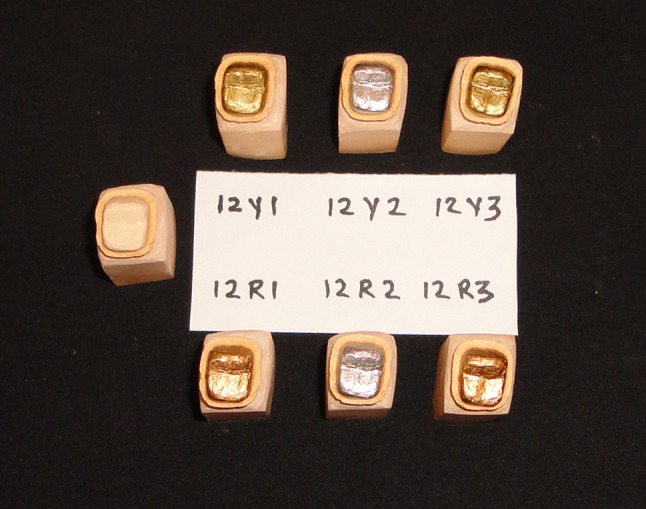
Six dies with DS applied and a control die
Die lubricant (Pico-Sep; Renfert GmbH, Germany) was applied, wax pattern (Crowax; Renfert GmbH, Germany) was fabricated for metal-ceramic crown, with a uniform thickness of 0.5 mm except at the finish line where it had 1 mm thickness so as to develop metal collar that covers 1 mm finish line. To minimize the error due to casting variables [18, 19], six wax patterns for a subject were sprued, invested (Begosol/Bellavest SH; Bego, Bremen, Germany) and cast with Nickel Chromium alloy (Bellbond plus; Bego, Germany) in the same ring. After divestment, copings were recovered and the intaglio surface of all copings was cleaned by sand blasting with 50 µ aluminum oxide. Castings cleaned of nodules under magnification and no additional relief was given to that provided by the die spacer. Clean copings with no defects were used for the study. Metal margins generally have more accurate fit than porcelain margins [20] hence copings and not porcelain fused to metal crown were utilized for seating. Similarly, six copings were fabricated for each subject; thus a total of 90 copings were fabricated.
Seating of Coping In Vitro
Each of six copings for a subject was seated on the die (without die spacer applied on it) using fit indicating material (Fit Checker II; GC Corporation, Tokyo, Japan). Use of rubber replica of cement space for measurement of pre-cementation space was followed by previous studies [14, 21]. Fit checker was mixed according to the manufacturer’s instructions, applied on the intaglio surface of coping and seated on the control die with a firm axial movement under finger pressure. The coping was loaded vertically by the Universal Testing Machine at 5 kg of constant load for 3 min. The procedure of dynamic loading [22] was simulated, by placing orangewood stick in between the coping and the compression head of the Universal Testing Machine (Fig. 2). The load was maintained for 3 min [23] while the fit checker sets. The optimum cementation force required to reduce the film thickness of cement was 5 kg for 1 min [10, 24]. The fit checker was then removed from inside of the coping; this had given three-dimensional pre-cementation space record, and then placed in a numbered container. The procedure was repeated for remaining copings.
Fig. 2.
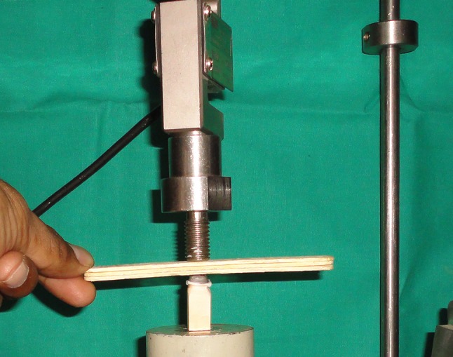
Seating of coping on control die in vitro
Seating of Coping In Vivo
Each of six copings for a subject was seated on the prepared tooth using fit checker. Fit checker was used just like it was done in laboratory step. The procedure of dynamic loading was simulated, by placing orangewood stick in between the coping and the opposing natural teeth. Then subject was asked to maintain the biting load for 3 min till the fit checker set (Fig. 3). The Fit checker was then removed from inside of the coping and placed in a numbered container. The procedure was repeated for remaining copings.
Fig. 3.
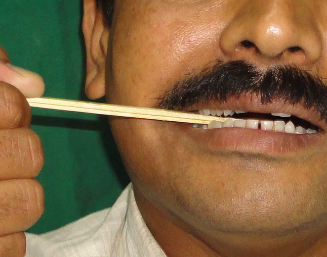
Seating of coping on prepared tooth in vivo
Measurement of Pre-cementation Space
The measurement of thickness of fit checker had given pre-cementation space between the coping and prepared tooth surface/die. The fit checker was marked with a fine marker pen at the middle of mesio-distal measurement; then it was sectioned buccolingually using sharp fine scissors (Fig. 4). Thickness of fit checker was measured using a Micrometer (Mitutoyo; Tokyo, Japan) at three locations—mid-occlusal, mid-axial and near finish line for mesial/distal half of the each sample (Fig. 5). Only one examiner made measurements, since the resilience of the fit checker would have made inter-examiner reliability difficult. The examiner was trained for measurements; after he was tested using five samples requiring three readings for each sample. He was able to constantly reproduce measurements to within 1 µ. The examiner was unknown of sample information regarding the die spacers, number of layers of die spacer and in vitro or in vivo record. Also samples were provided to the examiner for measurement randomly. The measurements of pre-cementation space were clustered with following titles:
| (1) CPA1, CPO1, CPF | (2) CPA2, CPO2, CPF2 | (3) CPA3, CPO3, CPF3 |
| (2) CYA1, CYO1, CYF1 | (5) CYA2, CYO2, CYF2 | (6) CYA3, CYO3, CYF3 |
| (3) LPA1, LPO1, LPF1 | (8) LPA2, LPO2, LPF2 | (9) LPA3, LPO3, LPF3 |
| (4) LYA1, LYO1, LYF1 | (11) LYA2, LYO2, LYF2 | (12) LYA3, LYO3, LYF3 |
Fig. 4.
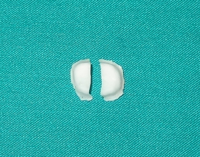
FC material sectioned buccolingually
Fig. 5.
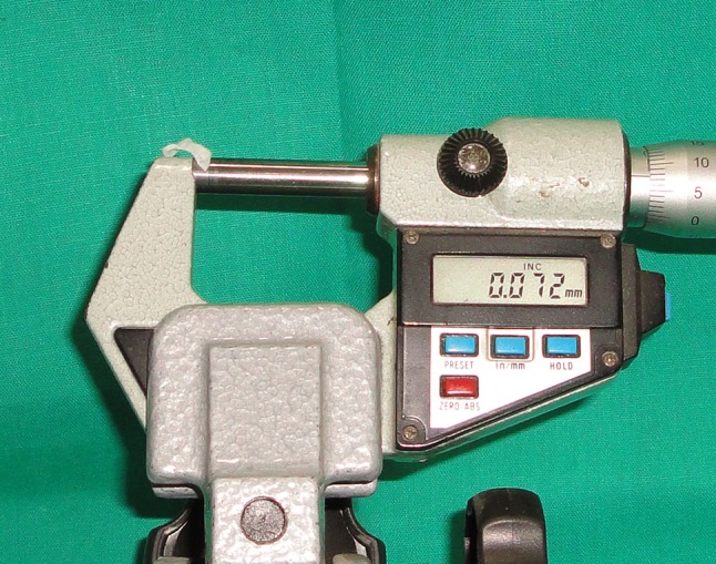
Measurement of PCS with micrometer
C—clinical (in vivo), L—laboratory (in vitro), P—Pico-fit die spacer, Y—Yeti die spacer, A—mid-axial measurement, O–mid-occlusal measurement, F—near finish line measurement, 1—one layer of die spacer, 2—two layers of die spacer, 3—three layers of die spacer
Here CPA1, LYO2, etc. represented individual groups.
Results
The pre-cementation space for each sample was measured in microns (µ) near finish line, mid-axial and mid-occlusal area (Tables 1, 2). There were total one hundred eighty samples- ninety clinical and ninety laboratory. The mean pre-cementation space and standard deviations were calculated for statistical analysis of all groups—(Table 3). The statistical analysis was performed using statistical software (Minitab version 14.0 and Systat version 12.0). The data was interpreted at a confidence interval of 95 %. The values of pre-cementation space measured at finish line, were not analyzed statistically, as no die spacer was applied near finish line.
Table 1.
Distribution of samples- pre-cementation space (in microns) in vivo for Pico-fit and Yeti die spacers
| In Vivo Pico-fit | One layer | Two layers | Three layers | In Vivo Yeti | One layer | Two layers | Three layers | ||||||||||||
|---|---|---|---|---|---|---|---|---|---|---|---|---|---|---|---|---|---|---|---|
| Sr. no. | F | A | O | F | A | O | F | A | O | Sr. no. | F | A | O | F | A | O | F | A | O |
| 1 | 41 | 54 | 94 | 39 | 65 | 100 | 53 | 87 | 115 | 1 | 35 | 51 | 92 | 45 | 66 | 90 | 47 | 90 | 108 |
| 2 | 40 | 51 | 109 | 41 | 88 | 100 | 60 | 104 | 129 | 2 | 28 | 47 | 114 | 47 | 77 | 106 | 50 | 100 | 116 |
| 3 | 43 | 59 | 120 | 35 | 60 | 112 | 47 | 90 | 128 | 3 | 37 | 49 | 94 | 49 | 84 | 89 | 48 | 84 | 105 |
| 4 | 35 | 50 | 102 | 59 | 79 | 96 | 39 | 81 | 109 | 4 | 48 | 60 | 114 | 52 | 79 | 97 | 55 | 95 | 142 |
| 5 | 32 | 46 | 101 | 46 | 81 | 95 | 40 | 88 | 108 | 5 | 26 | 37 | 85 | 45 | 72 | 105 | 41 | 83 | 112 |
| 6 | 26 | 37 | 98 | 53 | 83 | 80 | 31 | 79 | 105 | 6 | 25 | 39 | 82 | 50 | 84 | 100 | 39 | 68 | 120 |
| 7 | 29 | 48 | 110 | 33 | 58 | 89 | 41 | 81 | 105 | 7 | 42 | 48 | 112 | 40 | 62 | 86 | 45 | 80 | 121 |
| 8 | 25 | 51 | 105 | 29 | 69 | 82 | 40 | 83 | 109 | 8 | 28 | 42 | 103 | 30 | 55 | 82 | 33 | 69 | 94 |
| 9 | 37 | 61 | 112 | 32 | 57 | 104 | 50 | 94 | 127 | 9 | 22 | 48 | 97 | 31 | 58 | 92 | 46 | 86 | 121 |
| 10 | 58 | 74 | 118 | 52 | 73 | 101 | 40 | 91 | 121 | 10 | 52 | 64 | 128 | 32 | 65 | 102 | 37 | 84 | 133 |
| 11 | 49 | 62 | 91 | 28 | 67 | 100 | 57 | 79 | 108 | 11 | 50 | 62 | 121 | 29 | 68 | 110 | 52 | 88 | 112 |
| 12 | 37 | 49 | 109 | 51 | 69 | 117 | 33 | 71 | 106 | 12 | 38 | 47 | 110 | 40 | 65 | 112 | 39 | 83 | 108 |
| 13 | 38 | 50 | 100 | 31 | 59 | 112 | 30 | 63 | 101 | 13 | 35 | 53 | 112 | 48 | 65 | 120 | 34 | 73 | 124 |
| 14 | 38 | 51 | 106 | 43 | 75 | 101 | 41 | 81 | 109 | 14 | 29 | 44 | 92 | 44 | 62 | 80 | 31 | 70 | 109 |
| 15 | 21 | 45 | 99 | 36 | 65 | 94 | 55 | 95 | 114 | 15 | 35 | 52 | 100 | 37 | 60 | 90 | 44 | 92 | 117 |
F pre-cementation space near finish line, A pre-cementation space at mid-axial site, O pre-cementation space at mid- occlusal site
Table 2.
Distribution of samples- pre-cementation space (in microns) in vitro for Pico-fit and Yeti die spacers
| In vitro Pico-fit | One layer | Two layers | Three layers | In vitro Yeti | One layer | Two layers | Three layers | ||||||||||||
|---|---|---|---|---|---|---|---|---|---|---|---|---|---|---|---|---|---|---|---|
| Sr. no. | F | A | O | F | A | O | F | A | O | Sr. no. | F | A | O | F | A | O | F | A | O |
| 1 | 40 | 51 | 87 | 42 | 62 | 104 | 62 | 89 | 110 | 1 | 38 | 55 | 90 | 43 | 59 | 88 | 45 | 68 | 115 |
| 2 | 62 | 54 | 120 | 46 | 80 | 98 | 61 | 102 | 125 | 2 | 30 | 46 | 113 | 49 | 82 | 104 | 63 | 108 | 119 |
| 3 | 42 | 55 | 115 | 40 | 89 | 116 | 49 | 100 | 123 | 3 | 41 | 51 | 91 | 47 | 86 | 87 | 52 | 104 | 99 |
| 4 | 41 | 53 | 95 | 57 | 83 | 106 | 42 | 87 | 106 | 4 | 48 | 59 | 104 | 55 | 77 | 100 | 40 | 91 | 139 |
| 5 | 28 | 43 | 108 | 50 | 82 | 99 | 43 | 89 | 114 | 5 | 23 | 38 | 87 | 43 | 69 | 103 | 43 | 87 | 118 |
| 6 | 30 | 41 | 120 | 51 | 80 | 83 | 29 | 88 | 116 | 6 | 27 | 44 | 116 | 48 | 80 | 98 | 36 | 88 | 140 |
| 7 | 27 | 58 | 131 | 39 | 64 | 88 | 45 | 88 | 121 | 7 | 39 | 50 | 109 | 36 | 60 | 83 | 40 | 75 | 116 |
| 8 | 28 | 48 | 98 | 32 | 62 | 65 | 42 | 86 | 120 | 8 | 30 | 43 | 97 | 31 | 58 | 76 | 21 | 71 | 123 |
| 9 | 32 | 65 | 116 | 49 | 68 | 102 | 46 | 92 | 122 | 9 | 21 | 71 | 110 | 35 | 63 | 97 | 43 | 88 | 121 |
| 10 | 60 | 71 | 114 | 34 | 61 | 98 | 42 | 96 | 116 | 10 | 49 | 68 | 99 | 30 | 55 | 98 | 39 | 91 | 139 |
| 11 | 46 | 60 | 98 | 54 | 79 | 102 | 61 | 104 | 124 | 11 | 54 | 70 | 93 | 27 | 59 | 107 | 64 | 95 | 118 |
| 12 | 44 | 52 | 111 | 39 | 66 | 103 | 31 | 82 | 133 | 12 | 40 | 45 | 124 | 41 | 66 | 109 | 29 | 86 | 127 |
| 13 | 42 | 51 | 106 | 45 | 67 | 110 | 32 | 62 | 109 | 13 | 31 | 49 | 109 | 49 | 78 | 116 | 30 | 64 | 119 |
| 14 | 32 | 54 | 104 | 36 | 76 | 102 | 39 | 79 | 103 | 14 | 27 | 42 | 98 | 41 | 60 | 88 | 35 | 81 | 109 |
| 15 | 30 | 48 | 100 | 38 | 68 | 98 | 50 | 93 | 108 | 15 | 33 | 50 | 102 | 38 | 80 | 89 | 37 | 99 | 118 |
F pre-cementation space near finish line, A pre-cementation space at mid-axial site, O pre-cementation space at mid- occlusal site
Table 3.
Mean pre-cementation space and standard deviation (microns) for different GROUPS
| In vivo | In vitro | |||||||||||
|---|---|---|---|---|---|---|---|---|---|---|---|---|
| Pico-fit | Yeti | Pico-fit | Yeti | |||||||||
| Ia | IIb | IIIc | I | II | III | I | II | III | I | II | III | |
| Fd | ||||||||||||
| Me | 36.60 | 40.53 | 43.80 | 35.33 | 41.27 | 42.73 | 37.60 | 43.47 | 44.93 | 35.40 | 40.87 | 41.13 |
| SDf | 09.48 | 09.78 | 09.44 | 09.63 | 07.82 | 07.19 | 09.12 | 07.53 | 10.46 | 09.81 | 08.03 | 11.67 |
| Ag | ||||||||||||
| M | 52.53 | 69.87 | 84.50 | 49.53 | 68.13 | 83.00 | 53.60 | 72.47 | 89.10 | 52.10 | 68.80 | 86.40 |
| SD | 08.70 | 09.72 | 10.10 | 07.87 | 09.13 | 09.63 | 07.77 | 09.17 | 10.30 | 10.05 | 10.06 | 12.08 |
| Oh | ||||||||||||
| M | 104.93 | 98.90 | 112.93 | 103.7 | 97.40 | 116.10 | 108.20 | 98.30 | 116.67 | 102.8 | 96.20 | 121.30 |
| SD | 08.25 | 10.30 | 09.12 | 13.40 | 11.70 | 11.60 | 11.60 | 12.10 | 08.35 | 10.06 | 10.90 | 11.20 |
aOne layer of die spacer
bTwo layers of die spacer
cThree layers of die spacer
dFinish line
eMean
fStandard deviation
gMid axial site
hMid occlusal site
Comparison Between Varying Layers of Die Spacers
One way analysis of variance (ANOVA) test was used for evaluating the mean differences among groups. At the 95 % confidence interval, the ‘P’ values for ANOVA tests were less than 0.001. Though the differences given by one way ANOVA were significant, this test showed only collective results of all means therefore, individual Scheffe’s test was applied. Scheffe’s test compared- one layer group with two layers group, one layer group with three layers group and two layers group with three layers group—(Table 4).
Table 4.
Result of Scheffe’s test
| Groups compared | P value | Groups compared | P value |
|---|---|---|---|
| (CPA1,CPA2)* | <0.001 | (LPA1, LPA2)* | <0.001 |
| (CPA1,CPA3)* | <0.001 | (LPA1, LPA3)* | <0.001 |
| (CPA2,CPA3)* | <0.001 | (LPA2, LPA3)* | <0.001 |
| (CPO1,CPO2) | 0.213 | (LPO1, LPO2) | <0.052 |
| (CPO1,CPO3) | 0.073 | (LPO1, LPO3) | <0.112 |
| (CPO2,CPO3)* | <0.001 | (LPO2, LPO3)* | <0.001 |
| (CYA1,CYA2)* | <0.001 | (LYA1, LYA2)* | <0.001 |
| (CYA1,CYA3)* | <0.001 | (LYA1, LYA3)* | <0.001 |
| (CYA2,CYA3)* | <0.001 | (LYA2, LYA3)* | <0.001 |
| (CYO1,CYO2) | 0.379 | (LYO1, LYO2) | <0.052 |
| (CYO1,CYO3) | 0.030 | (LYO1, LYO3) | <0.112 |
| (CYO2,CYO3)* | <0.001 | (LYO2, LYO3)* | <0.001 |
* Significant difference
Comparison Between the Die Spacers- Pico-Fit and Yeti
To compare between the groups with Pico-fit die spacer and Yeti die spacer, student’s unpaired t test was applied. The results of student’s unpaired t-test are tabulated in Table 5.
Table 5.
Result of Student’s unpaired t test
| Student’s unpaired t test | P value |
|---|---|
| CPA1/CYA1 | 0.331 |
| CPA2/CYA2 | 0.619 |
| CPA3/CYA3 | 0.686 |
| CPO1/CYO1 | 0.771 |
| CPO2/CYO2 | 0.719 |
| CPO3/CYO3 | 0.411 |
| LPA1/LYA1 | 0.653 |
| LPA2/LYA2 | 0.320 |
| LPA3/LYA3 | 0.525 |
| LPO1/LYO1 | 0.194 |
| LPO2/LYO2 | 0.627 |
| LPO3/LYO3 | 0.209 |
P > 0.05 denotes non-significant difference
Comparison Between Clinical (In Vivo) and Laboratory (In Vitro) Findings
To correlate the measurements of pre-cementation space for clinical seating with laboratory seating, correlation analysis was carried out between respective pair of in vivo and in vitro groups. The r value (correlation coefficient value) for correlation between each pair of group is shown in Table 6.
Table 6.
Correlation analysis of PCS in vitro and in vivo
| Treatment pair | r value | Comment |
|---|---|---|
| LPA1, CPA1 | 0.892 | Positive correlation |
| LPA2, CPA2 | 0.435 | Positive correlation |
| LPA3, CPA3 | 0.744 | Positive correlation |
| LPO1, CPO1 | 0.595 | Positive correlation |
| LPO2, CPO2 | 0.819 | Positive correlation |
| LPO3, CPO3 | 0.267 | Positive correlation |
| LYA1, CYA1 | 0.785 | Positive correlation |
| LYA2, CYA2 | 0.681 | Positive correlation |
| LYA3, CYA3 | 0.578 | Positive correlation |
| LYO1, CYO1 | 0.190 | Positive correlation |
| LYO2, CYO2 | 0.949 | Positive correlation |
| LYO3, CYO3 | 0.604 | Positive correlation |
Discussion
Ideal cementation of fixed prosthesis leads to perfect marginal seal but unfortunately, this clinical procedure causes incomplete seating and marginal opening. Because of development of hydraulic pressure under the restoration, it causes incomplete seating of restoration. Amongst all the methods available, use of die spacer for internal relief of crown is the most popular and more accurate method. There is enough laboratory data but inadequate clinical data on thickness of die spacer or cement thickness for varying layers of die spacers; hence this combined (in vitro and in vivo) study was planned.
The mean pre-cementation spaces achieved in vivo for one, two and three layers of Pico-fit die spacer (Table 3) in the present study are in agreement with pre-cementation spaces achieved by respective layers of die spacer at the same three locations measured by Emtiaz et al. [25]. Similarly, the mean pre-cementation spaces achieved in vivo for one, two and three layers of Yeti die spacer (Table 3) in the present study are in agreement with pre-cementation spaces achieved by respective layers of die spacer at the same three locations measured by Emtiaz et al. [25]. The mean pre-cementation spaces for one layer of either of the die spacers in vivo and in vitro (Table 1) are comparable to cement thickness achieved by Fusayama et al. [8].
The range of pre-cementation space, 35–44 µ near finish line is consistent with mean measurements reported by White et al. [26] and Grajower et al. [12]. Pre-cementation spaces ranging 35–44 µ near finish line indicates copings were not completely seated on the die or prepared tooth, as die spacer was not applied near the finish line. Increased marginal opening of a crown will invariably occur with introduction of a luting agent regardless of the relief method used [23, 27].
ANOVA tests suggested that pre-cementation space achieved with one layer, two layers and three layers of die spacers differed from each others; hence the first hypothesis was rejected. Similar results were reported by Emtiaz et al. [25].
Pre-cementation space (Table 3) increased from one to two layers and from two to three layers at mid-axial sites while pre-cementation space decreased from one to two layers and increased from two to three layers at mid-occlusal sites. Differences in results (Table 4) for mid-occlusal groups as compared to mid-axial groups can be explained on the basis of findings of Grajower et al. [12] and Passon et al. [28]. When no die spacer is used or at low die spacer thicknesses, seating of the crown is arrested at the axial walls. With increasing die spacer thickness, the elevation decreases until a certain die spacer thickness value, seating of the crown becomes arrested at the shoulder margin [12]. The increase was slight when the original space was greater than 30 µ. The thickness, however, was markedly increased when the original space thickness was less than 30 µ [19].
Cement thickness under casting was generally greater than the original space thickness. [23, 29, 30] Cement film thickness may be greater than the maximum film thickness specified for cement and even more on occlusal area compared to axial areas. Passon et al. [28] assumed that with complete coping seating, the cement should be uniformly distributed to a thickness equal to the die spacer thickness plus the thickness caused by the cement film thickness at the unrelieved margin.
Results (Table 5) suggest that one, two and three layers of Pico-fit die spacer provides in vivo pre-cementation space equivalent to in vivo pre-cementation space for respective layers of Yeti die spacer for the mid-axial and mid-occlusal locations. Similarly, one, two and three layers of Pico-fit die spacer provides in vitro pre-cementation space equivalent to in vitro pre-cementation space for respective layers of Yeti die spacer for the mid-axial and mid-occlusal locations; therefore second hypothesis was rejected. This can be explained as die spacer application technique, wax pattern fabrication, casting procedure, method of seating, material used for seating and pre-cementation space measurement, all steps were similar for both the die spacers compared.
The r values (correlation coefficient values—Table 6) suggest positive correlation between the each of the in vivo and in vitro groups; therefore the third hypothesis was rejected. For clinical and laboratory seating, same coping, same material fit checker, dynamic method of loading were used; only different were the prepared tooth and die. Results suggest that with the present method, in vitro pre-cementation space for a sample provides nearly equal in vivo pre-cementation space for the same sample at same location and for similar number of layers of die spacer.
Clinical Significance
Main objective of internal relief with die spacer is to achieve minimal marginal opening. Two layers of die spacers resulted in lesser mid-occlusal pre-cementation space and greater seating of copings towards finish line. Hence, painting two layers of either Pico-fit or Yeti die spacer following the method of application suggested by manufacturer is recommended. By following the present methodology, pre-cementation space accomplished in laboratory may predict intraoral pre-cementation space. Mean pre-cementation space at mid-axial and mid-occlusal sites achieved with varying layers of either Pico-fit or Yeti die spacers was generally greater than the thickness of die spacer applied and clinical (also laboratory) pre-cementation space exceeded accepted range of thickness of die spacer which is 25–40 μ. Thus, clinically acceptable range of pre-cementation space needs to be studied.
Limitations of the Study
It was difficult to standardize the tooth preparation clinically, according to size, shape and surface area for all subjects. Though care was taken to avoid dimensional changes due to impression and die materials, which may have affected pre-cementation space. Fit checker used for seating of copings may not have performed exactly like the cements.
Conclusion
Within the limitations of the study the following conclusions were drawn: (1) Pre-cementation space differed significantly when compared between one and two, one and three and two and three layers of die spacers at mid-axial site and mid-occlusal site except between one and two layers and one and three layers at mid-occlusal site. Two layers of either of two die spacers resulted in lesser mid-occlusal pre-cementation space as compared to one and three layers denote greater seating of copings. Therefore, application of two layers of Pico-fit or Yeti die spacer is advisable. (2) Pre-cementation space accomplished with Pico-fit and Yeti die spacers did not differ significantly for same location, layers and in vitro and in vivo. (3) Pre-cementation space achieved in vitro was analogous to pre-cementation space achieved in vivo for respective location, layers and die spacer.
References
- 1.Kasloff Z. Casting techniques and some variables. J Prosthet Dent. 1961;11:533–536. doi: 10.1016/0022-3913(61)90236-0. [DOI] [Google Scholar]
- 2.Pilo R, Cardash HS, Baharav H, Helft M. Incomplete seating of cemented crowns: a literature review. J Prosthet Dent. 1988;59:429–433. doi: 10.1016/0022-3913(88)90037-6. [DOI] [PubMed] [Google Scholar]
- 3.Jorgensen KD. Factors affecting the film thickness of zinc phosphate cements. Acta Odontol Scand. 1960;18:479–490. doi: 10.3109/00016356009043879. [DOI] [Google Scholar]
- 4.Campagni WV, Preston JD, Reisbick MH. Measurement of paint-on die spacers used for casting relief. J Prosthet Dent. 1982;47:606–611. doi: 10.1016/0022-3913(82)90132-9. [DOI] [PubMed] [Google Scholar]
- 5.Hollenback GM. Precision gold inlays made by a simple technic. J Am Dent Assoc. 1943;30:99–109. doi: 10.14219/jada.archive.1943.0023. [DOI] [Google Scholar]
- 6.Tjan AHL, Sarkissian R, Miller GD. Effect of multiple axial grooves on the marginal adaptation of full cast-gold crowns. J Prosthet Dent. 1981;46:399–403. doi: 10.1016/0022-3913(81)90445-5. [DOI] [PubMed] [Google Scholar]
- 7.Webb EL, Murray HV, Holland GA, Taylor DF. Effects of preparation relief and flow channels on seating full coverage castings during cementation. J Prosthet Dent. 1983;49:777–780. doi: 10.1016/0022-3913(83)90347-5. [DOI] [PubMed] [Google Scholar]
- 8.Fusayama T, Ide K, Hosada H. Relief of resistance of cement of full cast crowns. J Prosthet Dent. 1964;14:95–106. doi: 10.1016/0022-3913(64)90124-6. [DOI] [Google Scholar]
- 9.Fusayama T. Factors and technique of precision casting. Part I and II. J Prosthet Dent. 1959;9(468):486. doi: 10.1016/0022-3913(59)90081-2. [DOI] [Google Scholar]
- 10.Council on Dental Materials and Devices Reports of Councils and Bureaus. Revised American National Standards Institute/American Dental Association Specification no. 8 for zinc phosphate cement. J Am Dent Assoc. 1978;96:121–123. doi: 10.14219/jada.archive.1978.0032. [DOI] [Google Scholar]
- 11.Reiger MR, Tanquist RA, Brose MO, Ali M. Measuring the thickness of a paint- on die spacer. J Prosthet Dent. 1987;58:305–308. doi: 10.1016/0022-3913(87)90045-X. [DOI] [PubMed] [Google Scholar]
- 12.Grajower R, Zuberi Y, Lewinstein I. Improving the fit of crowns with die spacers. J Prosthet Dent. 1989;61:555–563. doi: 10.1016/0022-3913(89)90275-8. [DOI] [PubMed] [Google Scholar]
- 13.Campbell SD. Comparison of conventional paint on die spacers and those used with the all-ceramic restorations. J Prosthet Dent. 1990;63:151–155. doi: 10.1016/0022-3913(90)90098-W. [DOI] [PubMed] [Google Scholar]
- 14.McLean JW, Von Fraunhofer JA. The estimation of cement film thickness by an in vivo technique. Br Dent J. 1971;131:107–111. doi: 10.1038/sj.bdj.4802708. [DOI] [PubMed] [Google Scholar]
- 15.Gonzalo E, Saurez MJ, Serrano B, Lozano JFL. A comparison of the marginal vertical discrepancies of zirconium and metal ceramic posterior fixed dental prostheses before and after cementation. J Prosthet Dent. 2009;102:378–384. doi: 10.1016/S0022-3913(09)60198-0. [DOI] [PubMed] [Google Scholar]
- 16.Soriani NC, Leal MB, Paulino SM, Pagnano VO, Bezzon OL. Effect of the use of die spacer on the marginal fit of copings cast in NiCr, NiCrBe and commercially pure Titanium. Braz Dent J. 2007;18:225–230. doi: 10.1590/S0103-64402007000300009. [DOI] [PubMed] [Google Scholar]
- 17.Eames WB, O’Neal SJ, Monterio J, Miller C, Roan JD, Cohen KS. Techniques to improve the seating of castings. J Am Dent Assoc. 1978;96:432–437. doi: 10.14219/jada.archive.1978.0090. [DOI] [PubMed] [Google Scholar]
- 18.Gavelis JR, Morency JD, Riley ED, Sozie RB. The effect of various finish line preparations on the marginal seal and occlusal seat of full crown preparations. J Prosthet Dent. 2004;45:138–145. doi: 10.1016/0022-3913(81)90330-9. [DOI] [PubMed] [Google Scholar]
- 19.Teteruck WR, Mumford G. The fit of certain dental casting alloys using different investing materials and techniques. J Prosthet Dent. 1966;16:910–927. doi: 10.1016/0022-3913(66)90014-X. [DOI] [PubMed] [Google Scholar]
- 20.Rosenstiel SF, Land MF, Fujimoto J. Contemporary fixed prosthodontics. 4. New Delhi: Mosby; 2007. pp. 761–763. [Google Scholar]
- 21.Rosenstiel SF, Gegauff AG. Improving the cementation of complete cast crowns: a comparison of static and dynamic seating methods. J Am Dent Assoc. 1988;117:845–848. doi: 10.14219/jada.archive.1988.0137. [DOI] [PubMed] [Google Scholar]
- 22.Koyano E, Iwaku M, Fusayama T. Pressuring techniques and cement thickness for cast restorations. J Prosthet Dent. 1978;40:544–548. doi: 10.1016/0022-3913(78)90090-2. [DOI] [PubMed] [Google Scholar]
- 23.Fusayama T, Ide K, Kurosu A, Hosoda H. Cement thickness between cast restorations and preparation walls. J Prosthet Dent. 1963;13:354–364. doi: 10.1016/0022-3913(63)90181-1. [DOI] [Google Scholar]
- 24.Horn H. The cementation of crowns and fixed partial dentures. Dent Clin North Am. 1965;23:65–81. [PubMed] [Google Scholar]
- 25.Emtiaz S, Goldstein G. Effect of die spacer on precementation space of complete-coverage restorations. Int J Prosthodont. 1997;10:131–135. [PubMed] [Google Scholar]
- 26.White SN, Sorensen JA, Kang SK. Improved marginal seating of cast restorations using a silicone disclosing medium. Int J Prosthodont. 1991;4:323–326. [PubMed] [Google Scholar]
- 27.Van Nortwick WT, Gettleman L. Effect of internal relief, vibration and venting on the vertical seating of cemented crowns. J Prosthet Dent. 1981;45:395–399. doi: 10.1016/0022-3913(81)90099-8. [DOI] [PubMed] [Google Scholar]
- 28.Passon C, Lambart RH, Lambart RL, Newman S. The effect of multiple layers of die spacers on crown retention. Oper Dent. 1992;17:42–49. [PubMed] [Google Scholar]
- 29.Carter SM, Wilson PR. The effect of die spacing on post-cementation crown elevation and retention. Aust Dent J. 1997;42:192–198. doi: 10.1111/j.1834-7819.1997.tb00121.x. [DOI] [PubMed] [Google Scholar]
- 30.Ortorp A, Jonsson D, Mouhsen A, Vult von Steyern P. The fit of cobalt-chromium three unit fixed dental prostheses fabricated with four different techniques: a comparative in vitro study. Dent Mater. 2011;27:356–363. doi: 10.1016/j.dental.2010.11.015. [DOI] [PubMed] [Google Scholar]