Abstract
Esophageal transport is a physiological process that mechanically transports an ingested food bolus from the pharynx to the stomach via the esophagus, a multilayered muscular tube. This process involves interactions between the bolus, the esophagus, and the neurally coordinated activation of the esophageal muscles. In this work, we use an immersed boundary (IB) approach to simulate peristaltic transport in the esophagus. The bolus is treated as a viscous fluid that is actively transported by the muscular esophagus, and the esophagus is modeled as an actively contracting, fiber-reinforced tube. Before considering the full model of the esophagus, however, we first consider a standard benchmark problem of flow past a cylinder. Next a simplified version of our model is verified by comparison to an analytic solution to the tube dilation problem. Finally, three different complex models of the multi-layered esophagus, which differ in their activation patterns and the layouts of the mucosal layers, are extensively tested. To our knowledge, these simulations are the first of their kind to incorporate the bolus, the multi-layered esophagus tube, and muscle activation into an integrated model. Consistent with experimental observations, our simulations capture the pressure peak generated by the muscle activation pulse that travels along the bolus tail. These fully resolved simulations provide new insights into roles of the mucosal layers during bolus transport. In addition, the information on pressure and the kinematics of the esophageal wall resulting from the coordination of muscle activation is provided, which may help relate clinical data from manometry and ultrasound images to the underlying esophageal motor function.
Keywords: fluid-structure interaction, immersed boundary method, esophageal transport, muscle activation
1 Introduction
Interactions between fluids and deformable structures are widespread in biological systems, and such interactions often involve complex moving interfaces and large structural deformations [1]. Esophageal transport is one such process, whereby the food bolus is transported to the stomach via the esophagus. The esophagus is a flexible, multi-layered tube that consists of mucosal, interfacial, circumferential, and longitudinal muscle layers. The pumping force required to produce this peristaltic transport process is generated by neurally coordinated muscle activation along the esophagus [2,3], and accounting for the full physiological details of the transport process is challenging. Simplified analytical models can provide some insights into this biophysical process [4] but are often limited in their scope. More complete models are needed to investigate esophageal pathophysiology, such as motility disorders, and hold the potential to advance diagnoses and patient treatment.
Previous studies on modeling esophageal transport have focused on specific, albeit important, subproblems, such as characterizing the material properties of each layer of the esophagus tube [5,6,7,8,9,10], investigating the flow of bolus with specified time-dependent bolus geometry or known lumen pressure [4,11,12], and estimating the muscle active tension based on known time-dependent pressure distribution [13,14]. To the best of our knowledge, however, there are no previous integrated computational models of esophageal transport that couple models of the bolus, the esophageal structure, and the muscle activation.
This work presents one such integrative model of esophageal transport that is based on the immersed boundary (IB) method [15]. The IB method is an approach to modeling fluid-structure interaction that was introduced to simulate the fluid dynamics of heart valves [16,17], and which has subsequently been applied to a broad range of problems in biology [15]. The IB method uses an Eulerian description of the momentum and incompressibility of the coupled fluid-structure system along with a Lagrangian description of the structural forces produced by the passive elasticity and active tension generation of the structure. The primary advantage of this formulation is that it avoids the need to employ body-fitted grids, and thereby eliminates the need to develop complex remeshing strategies as the immersed structure deforms [15,18]. In this paper, we present a fully resolved fluid-structure interaction model of esophageal transport that includes detailed descriptions of the esophageal wall, the bolus, and their interaction. This model is fully resolved in the sense that it does not assume simplified fluid dynamics or structural deformations.
In our model, the majority of the computational domain is occupied by the immersed body, and the fluid (i.e., the bolus) is confined in a narrow lumen. Thus, it is important to describe the mechanical response of the esophagus tube. To that end, we discretize the fibers of the esophagus into springs and beams and associate a volumetric patch with each such spring and beam. This allows us to compute the spring and beam parameters from the material properties of the esophagus (e.g., its Young’s modulus).
To verify our immersed boundary scheme, we consider a standard benchmark problem of flow past a cylinder at various Reynolds numbers, and we compare the results for drag and lift coefficients and Strouhal number of the flow with those given in the literature. Then, to test the fiber-based esophagus tube model, we simulate the problem of dilation of a three-dimensional tube and compare the numerically obtained inner fluid pressure with an analytically derived solution.
To simulate bolus transport in a physiologically realistic manner, an esophagus model is constructed as a four-layered structure. Muscle activation that results in the peristaltic motion of the esophagus is modeled via springs with dynamic rest lengths. To handle the numerical challenge arising from large deformations of the mucosal layer, we employ a locally refined structural discretization that ensures that the Lagrangian structure does not “leak” even under very large deformations [15]. We consider three cases with different muscle activation models and mucosal layer fiber arrangements, and we discuss the key features related to muscle cross-section area and pressure peaks during bolus transport.
2 Mathematical formulation
2.1 The immersed boundary method
The IB formulation of problems of fluid-solid interaction employs an Eulerian description for the momentum equation and the divergence-free condition and a Lagrangian description of the deformation of the immersed structure and the resulting structural forces. Here, we use the same notation for the Eulerian and Lagrangian coordinates as detailed in Griffith [19]. Specifically, we let x = (x, y, z) ⊂ U denote fixed Cartesian coordinates, in which U ⊂ ℝ3 denotes the fixed domain occupied by the entire fluid-structure system. We use s = (s1, s2, s3) ⊂ Ω to denote the Lagrangian coordinates attached to the immersed structure, in which Ω ⊂ ℝ3 denotes the fixed material coordinate system attached to the structure. For simplicity of implementation, we consider that the fluid-structure system possesses a uniform mass density ρ and dynamic viscosity μ. This simplification implies that the immersed structure is neutrally buoyant and viscoelastic rather than purely elastic. An extension of the present mathematical formulation to problems with nonuniform mass densities or viscosities is also feasible; see Ref. [20] for details.
The equations of motion of the coupled fluid-structure system are [15]
| (1) |
| (2) |
| (3) |
| (4) |
| (5) |
Eqs. (1) and (2) are the incompressible Navier-Stokes equations written in the Eulerian form, u(x, t) is the Eulerian velocity, p(x, t) is the pressure, and g(x, t) is the Eulerian elastic force density. Eq. (5) describes the elastic force in the immersed body in Lagrangian form, in which G(s, t) is the elastic force density and 𝒢 : X ↦ G is a time-dependent functional that determines the Lagrangian force density from the current configuration of the immersed structure. Interactions between Lagrangian and Eulerian variables in eqs. (3) and (4) are mediated by integral transforms with a three-dimensional Dirac delta function kernel δ(x) = δ(x)δ(y)δ(z). Specifically, eq. (3) converts the Lagrangian force density G(s, t) into an equivalent Eulerian force density g(x, t), and eq. (4) determines the physical velocity of each Lagrangian material point from the Eulerian velocity field, thereby effectively imposing the no-slip condition along the fluid-solid interface. The discretized version of these equations used in this work employs a regularized version of the delta function, denoted δh(x) = δh(x)δh(y)δh(z); for details on the construction of such regularized delta functions, see Ref. [15]. The details on the spatial discretization of Eulerian fluid system (i.e., eqs. (1) and (2)), Lagrangian-Eulerian interaction equations, (i.e., eqs. (3) and (4)), and the temporal discretization of the system of equations can be found in refs. [19,21]. In the following section, we discuss the Lagrangian discretization of Eq. (5) to characterize the material elasticity of the immersed structure.
2.2 Material elasticity
The specific form of the mapping function 𝒢 : X ↦ G is dictated by the model of material elasticity of the immersed body. To that end, Chadwick [22], Ohayon and Chadwick [23], and Tozeren [24] proposed the “fluid-fiber” and the “fluid-fiber-collagen” models to characterize the material elasticity of biological tissues. They assumed the tissues to be an aggregation of elastic fibers that are embedded in a soft matrix. These models were used to describe the esophageal wall by Nicosia and Brasseur [14]. They considered the muscle layer as a family of fibers and discarded the elasticity of the soft matrix. Inspired by the success of their model [14], we also ignore the elasticity of the soft ground matrix in the esophageal wall and model all esophageal layers as families of continuous fibers embedded in the background fluid. Thus, the material elasticity of the esophagus tube is essentially represented by the fiber elasticity, which is approximated using springs and beams in our discretized IB scheme. By contrast, Ghosh et al. [13] have modeled the esophageal muscle layer as a family of incompressible continuous fibers embedded in a soft isotropic matrix. Such models will be explored in our future work.
We describe the fiber-based material elasticity in terms of a strain-energy functional E = E[X(·, t)]. The corresponding Lagrangian elastic force density can be derived by taking the Fréchet derivative of E as
| (6) |
in which ℘ denotes the perturbation of a quantity. Since the elastic properties of the structure are described in terms of a family of elastic fibers that resist extension, compression and bending, the strain-energy functional E = E[X(·, t)] can be decomposed into a stretching part Es that accounts for the extension and compression of the fibers, and a bending part Eb which accounts for the resistance of the fibers to bending, i.e., E = Es + Eb.
2.3 Elastic springs and beams
We use a three-dimensional spring network to represent the elastic stretching energy Es of the esophagus tube. Three families of springs are employed for the radial, circumferential, and axial fibers of the tube. By contrast, we only include axial beams in esophagus model to account for the bending energy Eb, as the significant curvature change for the long esophageal tube occurs primarily along the axial direction.
In our implementation of the IB method [19], instead of computing the elastic force density, we compute the elastic force on each Lagrangian node, which is then spread to the Eulerian grid (via eq. (3)) to obtain the equivalent Eulerian force density. To relate the spring and beam constants to the material properties of the esophagus (such as its Young’s modulus), we associate a volumetric patch with each spring and beam. To obtain the volumetric patch, we describe the tube in cylindrical coordinates (r, θ, z) with the reference configuration given by (a ≤ r ≤ b, 0 ≤ θ ≤ 2π, 0 ≤ z ≤ l), in which a, b, and l are the inner radius, the outer radius, and the length of the tube in the reference configuration, respectively. Let (ri, θj, zk) denote a nodal point of the tube, with Δri = ri+1 − ri, Δθj = θj+1 − θj, and Δzk = zk+1 − zk denoting the spacing along r, θ, and z coordinates. Then, uniform spacing Δr, Δθ, and Δz will be obtained if we let Δri = Δr, Δθj = Δθ, and Δzk = Δz. Depending on whether any of the three types of springs or an axial beam lies in the interior of the structure or its boundary, different volumetric patches (interior or boundary patches) will be associated with them. We distribute the nodes of the structural discretization so that volumetric patches of each type Ptype (i.e., patches associated with radial, axial, or circumferential springs or with axial beams) do not overlap and sum to the volume of the esophagus tube. This can be written as
| (7) |
in which, Vesophagus is the volume of the esophagus, Ntype is the number of patches of the same type, and I and J are patch indices.
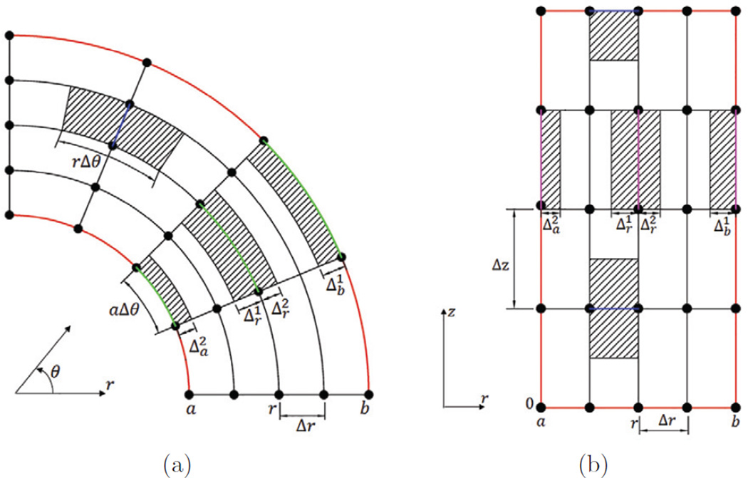
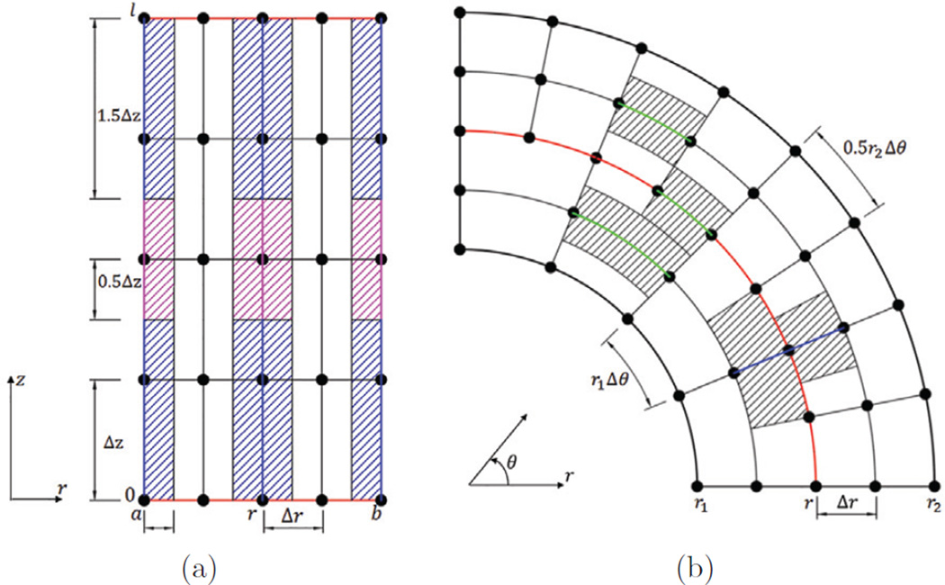
Fig. 1(a) and 1(b) show the volumetric patches of various springs in the (r, θ) plane and the (r, z) plane, respectively. Fig. 2(a) shows the patches associated with axial beams. Cases with nonuniform circumferential spacing are also considered in this work. In particular, we consider cases with Δθ for inner layers and 0.5Δθ for outer layers of the tube. The patches associated with the circumferential springs in (r, θ) plane for the nonuniform circumferential spacing are shown in Fig. 2(b). Once the patches for the discrete springs and beams are obtained, the elastic force due to extension, compression, and bending of the fibers can be computed with given material parameters. Next we discuss how spring and beam constants are obtained in our model from the elastic modulus of the fibers.
Fig. 1.
(a) Schematic of patches (hatched areas) associated with radial springs and circumferential springs in (r, θ) plane. Two boundaries of the tube shown here are the inner (r = a) and the outer surface (r = b). In (r, θ) plane, the patch of a radial spring connected by nodes (r, θ, z) and (r + Δr, θ, z) is (r, r + Δr) × (θ − 0.5Δθ, θ + 0.5Δθ). The patch of a circumferential spring connected by the nodes (r, θ, z) and (r, θ + Δθ, z) is for a < r < b, for r = b, and for r = a. Here and are such that the circumferential patch is partitioned into two equal volumes. (b) Schematic of patches (hatched areas) associated with radial springs and axial springs in (r, z) plane. The boundaries of the tube shown here are: the inner (r = a); outer (r = b); lower (z = 0); and upper (z = l) surfaces. In the (r, z) plane, the patch of a radial spring connected by nodes (r, θ, z) and (r + Δr, θ, z) is (r, r + Δr) × (z − 0.5Δz, z + 0.5Δz) for 0 < z < l; (r, r + Δr) × (z − 0.5Δz, z) for z = l and (r, r + Δr) × (z, z + 0.5Δz) for z = 0. The patch of an axial spring connected by nodes (r, θ, z) and (r, θ, z + Δz) is for a < r < b, for r = b, and for r = a.
Fig. 2.
(a) Schematic of patches (hatched areas) associated with axial beams in the (r, z) plane. The boundaries of the tube shown here are: the top z = l and the bottom z = 0. For a beam that has a node on the top or bottom surface of the tube, its patch volume is: V = 1.5riΔzΔθΔr for a < r < b; or V = 0.75riΔzΔθΔr for (r − a)(r − b) = 0. For a beam that does not have a node at the top or bottom surface of the tube, its patch volume is: V = riΔzΔθΔr for a < r < b or V = 0.5riΔzΔθΔr if (r − a)(r − b) = 0. (b) Schematic of patches (hatched areas) associated with radial springs and circumferential springs in the (r, θ) plane with nonuniform circumferential spacing. Note that there is an interface between the two layers that have different spacing in θ. Compared with the case of uniform Δθ, only circumferential springs located on the interface need special treatment.
Spring constant
We assume a linear relationship between the stress and strain of a spring, sp, which provides resistance to extension and compression of a fiber. If the stress and strain of the spring are defined with respect to the undeformed configuration, then we have
| (8) |
| (9) |
in which σ, ε, and F are the stress, strain, and internal force of the spring, respectively, S is the elastic modulus of the fiber, l is the current length, L is the rest length, and A is the undeformed cross sectional area. Consequently, the expression for the spring nodal forces and for nodes I1 and I2 connected by the spring are given by
| (10) |
in which, K = SA/L is the spring constant (also called the spring stiffness). The undeformed cross sectional area A can be obtained from the associated patch of the spring, A = Vsp/L, in which Vsp is the volume of patch of the spring.
Beam constant
A beam b associated with three nodes I1, I2, and I3, provides resistance to bending and sets a preferred (possibly a time-dependent) curvature of the fiber. The nodal forces for the beam , and can be obtained from the Fréchet derivative of the bending energy as
| (11) |
in which, cb is the bending stiffness, is the associated patch of the beam, and s = (s1, s2, s3) are (Lagrangian) curvilinear coordinates chosen such that s1, s2 = constant along the beam. is the preferred configuration, which in present work satisfies . Thus,
| (12) |
We approximate the second derivative in eq. (12) in the reference configuration of the tube and assume the three beam nodes to be on the same line. This implies small bending deformation. With qi (for i = 1, 2, 3) labeling the three nodes of the beam, we construct a shape function Ni for node qi in the local coordinate system q to obtain and :
| (13) |
| (14) |
| (15) |
Thus, eq. (12) evaluates as
| (16) |
in which, is the volume of the patch associated with the beam and . For the case of uniform distance between neighboring nodes of a beam in the reference configuration, i.e., when q2−q1 = q3−q2 = Δq, simple expression for the nodal forces can be obtained as below,
| (17) |
The bending coefficient cb in the above equation can be determined from the relation , in which I and A are the second moment of area and area of cross section of the beam, respectively.
3 Verification cases
3.1 Flow past a cylinder
As a first test case, we consider the problem of flow past a rigid circular cylinder. This problem has been the subject of many theoretical, experimental, and numerical studies, and the hydrodynamic force on the cylinder at various Reynolds numbers are readily available for comparison. Here, we conduct two-dimensional simulation of cases at Reynolds numbers 20, 40, and 200. In these simulations, instead of modeling the rigid cylinder as a 2D circular disk, we model only the circular boundary of the disk as a rigid boundary immersed in a fluid. Specifically, we consider a cylinder of diameter D centered at the origin of the domain. The circular boundary (i.e. the circle with the diameter D, centered at the origin) is actually modeled and discretized into a series of Lagrangian nodes, denoted by {si|i = 1, 2, …}. The zero-velocity condition along Lagrangian node si is enforced using the penalty method:
| (18) |
in which, F(si, t), X(si, t), and U(si, t) are the Lagrangian nodal force, nodal position, and nodal velocity, respectively. κ1 and κ2 are two positive penalty parameters that are chosen large enough that the motion of Lagrangian nodes is not noticeable. The circle is immersed in a large fluid domain. The size of fluid domain is taken to be [−32D, 32D] × [−32D, 32D] for the cases with Re = 20 and 40, while a domain of [−16D, 48D] × [−32D, 32D] is used for the case with Re = 200 to capture shed vortices behind the body. Along the left side of the domain, we specify velocity boundary conditions: (ux, uy) = (uo, e(y, t)), in which e(y, t) is zero for the cases with Re = 20 and 40, but a decaying sinusoidal function for case with Re = 200 to introduce an initial perturbation. Along the right side of the domain, we specify zero-traction boundary conditions: (tx, ty) = (0, 0). Along the top and bottom of the domain, we use mixed boundary conditions: (tx, uy) = (0, 0). We set the density of both fluid and cylinder as ρ, and thus the Reynolds number is , in which μ is the dynamic viscosity of the fluid. Here we nondimensionalize the system based on uo, ρ and D. Then , and .
To resolve the boundary layer and shed vortex structures, we perform simulations on an adaptively refined grid (Griffith et al. [25]). The mesh size of the fluid grid in the region containing the Lagrangian nodes and shed vortices is h = Δx = Δy = 0.01. The circle that represents the rigid boundary is discretized into No = 315 equally spaced Lagrangian nodes, so that the spacing between two neighboring nodes is about h. The time step is chosen as Δt = 10−3 and the total simulation time is 150. As discussed in Lai and Peskin [26], the drag and lift, denoted by FD(t) and FL(t), can be determined by computing the total forces on all the Lagrange nodes: . Then the drag coefficient is , the lift coefficient is , and the Strouhal number is , in which ωq is the vortex shedding frequency.
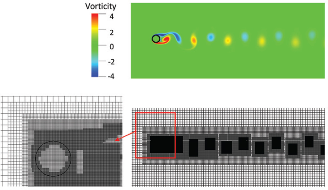
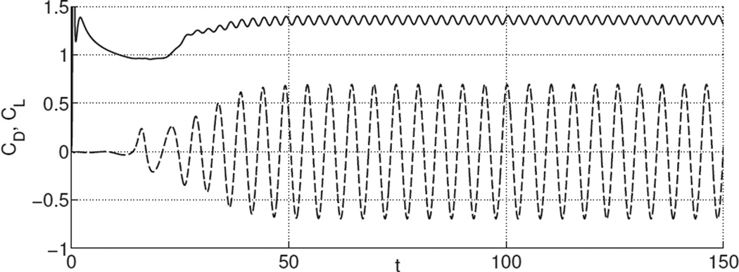
As it is expected, at Re = 20 and Re = 40, steady flow is achieved and drag and lift coefficients become constant in time after short transients. At Re = 200, the flow becomes unstable, with vortices shed behind the body, as shown in Fig. 3. Consequently, the drag and lift coefficients become periodic as shown in Fig. 4. The drag coefficients for cases with Re = 20, 40, and 200, and the lift coefficient and Strouhal number for the case with Re = 200 are listed in Table 1. They are all found to be in good agreement with results from previous studies.
Fig. 3.
Vorticity (Upper) and adaptively refined mesh resolving the region containing a circular cylinder (Lower left) and vortices (Lower right) at Re = 200 and t = 150.
Fig. 4.
Coefficients of drag (solid line) and lift (dashed line) for flow past a cylinder as a function of time at Re = 200.
Table 1.
Comparison of drag coefficient (CD) for flow past a cylinder from experimental and numerical studies at Re = 20, 40, and 200. For the case with periodic vortex shedding at Re = 200, comparison of lift coefficient (CL) and Strouhal number (St) is also presented.
| Study | CD | CL | St | |
|---|---|---|---|---|
| Re = 20 | Present | 2.06 | - | - |
| Taira and Colonius [27] | 2.06 | - | - | |
| Tritton [28] | 2.09 | - | - | |
| Dennis and Chang [29] | 2.05 | - | - | |
| Linnick and Fasel [30] | 2.06 | - | - | |
| Re = 40 | Present | 1.54 | - | - |
| Taira and Colonius [27] | 1.54 | - | - | |
| Tritton [28] | 1.59 | - | - | |
| Dennis and Chang [29] | 1.52 | - | - | |
| Linnick and Fasel [30] | 1.54 | - | - | |
| Re = 200 | Present | 1.36 ± 0.046 | ±0.69 | 0.200 |
| Taira and Colonius [27] | 1.35 ± 0.048 | ±0.68 | 0.196 | |
| Linnick and Fasel [30] | 1.34 ± 0.044 | ±0.69 | 0.197 | |
| Liu et al. [31] | 1.31 ± 0.049 | ±0.69 | 0.200 | |
| Bhalla et al. [32] | 1.39 | - | 0.200 | |
3.2 Dilation of a cylindrical tube
For the fiber-based IB scheme, Griffith [21,33] has studied convergence properties for various 2D cases. Here we present a test case of a 3D elastic cylindrical tube undergoing dilation to verify the solution methodology. A cylindrical tube composed of three families of continuous fibers (i.e., axial, circumferential, and radial fibers) is immersed in a rectangular fluid domain. We nondimensionalize the system based on the inner radius of the cylindrical tube and the density and viscosity of the fluid. The tube’s reference configuration is described in cylindrical coordinates (r, θ, z), with 1 ≤ r ≤ 1 + T, 0 ≤ θ ≤ 2π, 0 ≤ z ≤ 10, in which T is the tube thickness. The fluid domain is described in Cartesian coordinates (x, y, z) with −2 ≤ x ≤ 2, −2 ≤ y ≤ 2, 0 ≤ z ≤ 10. The dimensionless Young’s modulus S of all fibers is taken to be the same, S = 4 × 10⁴.
The dilation process includes two phases. The first phase is an inflation phase. This is modeled by adding fluid in the domain from the top end while keeping its bottom end closed. The second phase is the relaxation phase. The relaxation phase continues until a stationary state is reached, at which the inertial and viscous terms are approximately three orders of magnitude smaller than the pressure term. Thus, the pressure force from the constraint of fluid incompressibility is balanced by the elastic force in the tube. The simulations are carried by specifying the following boundary conditions for the fluid domain: traction (normal and tangential) free boundary conditions for the four lateral surfaces of the domain; zero-velocity boundary condition for the bottom surface; and a time-dependent velocity boundary condition for the top surface. On the top surface, the tangential velocity is zero and the normal velocity is u · n = −u0h(t)(1 − x2 − y2) if x2 +y2 ≤ 1, and zero otherwise. Here, h(t) is a decreasing function of time which vanishes at the end of the inflation process.
We assume a plain strain state for this relatively long tube at the final equilibrium state. Let U(r) denote the radial displacement field of the tube in the middle region, then by assuming plane strain conditions (i.e., a sufficiently long tube) in the final equilibrium state, an analytic expression for the inner pressure can be obtained (see Appendix A),
| (19) |
Here, , ri and ro are the deformed inner and outer radius, respectively; Ri and Ro denote the initial inner and outer radius, respectively. Thus, ri = Ri+U(ri), with U(ri) denoting the radial displacement of the inner surface of the tube and . We use the observed U(ri) in our simulations, and compare the numerical and predicted analytic values of the inner pressure, denoted as Pnumerical and Panalytic, respectively.
Here, we conduct test cases with different tube thickness and dilation levels, where higher dilation level is simulated by adding more fluid into the tube during the dilation phase. For each case, the Eulerian computational domain is discretized using an N × N × 50 Cartesian grid, whereas the Lagrangian structural domain is described using a cylindrical coordinate system (r, θ, z) and discretized using an Nr × Nθ × 100 mesh. To prevent the fluid from leaking out of the structure, we keep the grid size of Lagrangian mesh smaller than that of Eulerian mesh. The grid number for cases with different tube thickness is listed in Table 2. For a thicker tube of thickness T = 1, we use nonuniform Δθ for inner and outer layers, with Nθ = 64 for the inner and Nθ = 128 for the outer layers.
Table 2.
Error in the inner pressure for different tube thickness T. U(ri) and Pnumerical are radial displacement of the inner surface and inner pressure in the middle section of the tube, respectively. The relative error is
| T | Nr × Nθ | N | U(ri) | Pnumerical | Panalytic | εp |
|---|---|---|---|---|---|---|
| 0.2 | 4 × 128 | 40 | 0.07989 | 399.4 | 403.14 | 9.28e-3 |
| 0.5 | 10 × 128 | 40 | 0.07410 | 699.9 | 710.78 | 1.53e-2 |
| 1 | 6 × 64 + 4 × 128 | 20 | 0.07313 | 961.4 | 972.30 | 1.12e-2 |
As can be seen from Table 2 and Table 3, our fiber-based tube model is able to capture the analytical trend for various tube thickness and dilation levels, with relative error below 5%.
Table 3.
Error in the inner pressure for different dilation levels with tube thickness T = 0.2. Higher dilation level is simulated by adding more fluid in the tube, as shown by the increase of U(ri). The relative error
| Dilation level | U(ri) | Pnumerical | Panalytic | εp |
|---|---|---|---|---|
| Level 1 | 0.02827 | 159.7 | 161.24 | 9.57e-3 |
| Level 2 | 0.07989 | 399.4 | 403.14 | 9.28e-3 |
| Level 3 | 0.15658 | 652.7 | 663.85 | 1.68e-2 |
| Level 4 | 0.23483 | 805.2 | 840.9 | 4.25e-2 |
4 Esophageal transport
In the previous section, we showed that our IB formulation for an elastic tube is able to capture the analytical trend of a dilation process. In this section, we extend the elastic tube model to describe esophageal transport.
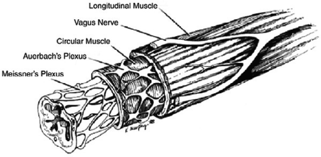
The human esophagus is a long multi-layered composite tube that consists of inner mucosal-submucosal layers (collectively referred to as “mucosal” layer) and outer muscle layers which in turn include the circular and longitudinal muscle layers (so named because of their fiber orientations [34]). The anatomy of the human esophagus is illustrated in Fig. 5. In vitro tests show that there exists a weak connecting tissue, referred to as the “interfacial” layer, between the muscle and mucosal layers [35]. Depending on its content, the bolus is generally considered as a Newtonian fluid, with its viscosity varying from one centipoise (cP) to several hundred centipoise [36]. The overall volume of the bolus is on the order of a few milliliters [37]. Studies of Pouderoux et al. [2] and Mittal et al. [3] suggest that during bolus transport, the circular muscle contraction is well coordinated with the longitudinal muscle shortening. It is this key activation pattern that is used in our esophageal muscle model that enables the transport of the “tear” shaped bolus [4,11] through the esophagus.
Fig. 5.
The multiple layers of the esophagus. The inner most layer is the mucosal layer (including mucosa and submucosa), which is highly folded at rest; the outer layers are muscle layers including circular muscle layer and longitudinal muscle layer (reproduced with permission from Kahrilas [34]).
4.1 Geometry, boundary conditions and material properties
The reference configuration of the esophagus model is taken to be a long straight cylindrical tube made up of elastic fibers. There are five important components in our esophagus model: (1) inner layer of mucosa (IM); (2) outer layer of mucosa (OM); (3) interfacial (IF) layer; (4) circular muscle (CM); and (5) longitudinal muscle (LM). The IM and OM layers together represent the mucosal layer of the esophagus, which we split into two layers for numerical purposes (see Sec. 4.3). The length of the esophagus tube is taken to be 240 mm, as the typical human esophagus length is in the range of 180–250 mm [38]. The thin liquid layer confined in the narrow esophageal lumen is assumed to have a circular cross section in the reference configuration with a radius of 0.3 mm. The thickness of each esophageal wall component is obtained based on the clinical data of human esophagus at non-rest state (i.e., with an intruded catheter in the esophagus). The thickness of each layer at rest is listed in Table 4 and is based on the clinical data of Mittal et al. [39]. The entire esophagus is immersed in a fluid region of size (−7 mm, 7 mm) × (−7 mm, 7 mm) × (−25 mm, 245 mm). On the six surfaces of the fluid box, we impose stress-free boundary conditions. We also fix the esophageal top end, which, in the physiological situation, is constrained by the upper esophageal sphincter. A schematic of the overall model is shown in Fig. 6. Here, we consider the transport of an initially filled bolus in the upper end of esophagus. For all the cases presented here, we take uniform viscosity of 10 cP and uniform density of 1 g/cm3 for both the fluid and the esophagus tube.
Table 4.
Thickness of each esophageal layer: clinical data [39] and data used in our model. Note that the clinical test obtains the thickness of each layer at its non-rest state, with esophageal lumen dilated by the intruded catheter. Computer model adopts the thickness of each layer at its rest state. The thickness of mucosal layer measured based on the ultrasound image is much lower than the thickness at rest, as the intruded catheter will distend the mucosal layer significantly and reduce the layer thickness.
| Unit (mm) | Lumen radius |
Mucosa thickness |
IF thickness |
CM thickness |
LM thickness |
|---|---|---|---|---|---|
| Clinical data | 3.5 | 1.85 | NA | 0.55 | 0.49 |
| Computer model | 0.3 | 3.2 | 0.6 | 0.6 | 0.6 |
Fig. 6.
Schematic (not drawn to scale) of the computational domain consisting of the elastic esophagus and a viscous fluid. The elastic esophagus, a cylindrical tube with its top end fixed, is immersed in the background fluid in our 3D computational model. The upper esophagus is initially filled with a bolus, and the lower part is filled with a thin liquid layer in the lumen. Traction-free boundary conditions are applied to all surfaces of the rectangular computational domain.
The esophageal tissue is generally modeled as a nonlinear anisotropic elastic or pseudo-elastic material. The reported material properties, such as the modulus of the muscle layers in the circumferential and longitudinal orientations, are substantially different [5,6,7,8,9,10]. Here we assume an elastic behavior of each fibrous esophageal layer. Such models have been used to estimate the muscle tension [14]. The elastic modulus for the radial, circumferential, and axial fibers is taken as S = 4 kPa. The interfacial layer that loosely connects the muscle and mucosal layer consists of only radial fibers with modulus S = 0.0004 kPa. For the mucosal layer, Stavropoulou [10] characterized the elasticity of the mucosal layer in their axial and circumferential directions, which can be represented by axially-circumferentially-radially arranged fiber network. By contrast, Natali et al. [6] considered the mucosal layer to comprise two families of helical fibers embedded in a matrix tissue. Thus, to demonstrate the capabilities of our modeling approach, we consider both fiber arrangements of the mucosal layer in Sections 5.1 and 5.3.
4.2 Muscle activation
In vivo experiments [2,3] show that during normal esophageal transport, there is well-coordinated circular muscle (CM) contraction and longitudinal muscle (LM) shortening. A quantitative model to characterize the contraction and shortening process in terms of neuronal firing or reaction kinetics in muscles is not available; however, experiments show that there is a precise synchrony between the two types of muscle activation patterns [2,3]. In our model, this sequential activation is implemented by dynamically changing the rest lengths of the fibers. Specifically, let z denote the vertical coordinate based on the initial configuration of the esophageal tube, with the bottom end of the esophagus as the origin z = 0, and the top as the end z = L. Then an active spring representing a section of one active muscle fiber has its rest length r(z, t) given by
| (20) |
in which, r0 is the spring’s initial rest length, c is the speed of the activation wave, t0 is the initiation time of activation, a(z, t) is the reduction ratio, and ΔL is the contracting segment’s length in the reference coordinate system. Eq. (20) gives the rest length of a spring at its rest, activation and relaxation state, respectively. The equation also shows, at any time, the whole esophageal tube has a contracting segment with a vertical length ΔL. The variation of muscle activation along this contracting segment will likely influence bolus transport. To understand this influence, we propose two muscle activation models, namely uniform muscle activation and nonuniform muscle activation. They differ by how the reduction ratio a(z, t) is distributed along the contracting segment ΔL,
- Uniform muscle activation:
(21) - Nonuniform muscle activation:
(22)
in which a0 is a constant, z0(t) is the z-coordinate at the vertical center of the contraction segment, and λ is the parameter that controls the width of the Gaussian distribution in eq. (22). The common parameters of muscle activation model used in all the cases of esophageal transport are listed in Table 5. a(z, t) differs in test cases depending on whether uniform muscle activation or nonuniform muscle activation is used.
Table 5.
Model parameters for the circular muscle (CM) contraction and longitudinal muscle (LM) shortening used in all the cases. The muscle activation model is based on eq. (20).
| Muscle activation type | c (mm/s) | L (mm) | t0 (s) |
|---|---|---|---|
| CM contraction | 100 | 60 | 0 |
| LM shortening | 100 | 60 | 0 |
4.3 Numerical issues
Esophageal transport involves multiple length scales, which is evidenced by the fact that the esophageal length is 240 mm, while the lumen radius at rest is only 0.3 mm. The requirement of resolving the narrow lumen dictates the grid size of the problem. More challenging in terms of computational modeling is the large deformation of the inner lumen, which results from the dilation caused by bolus movement. This can be seen in Fig. 9 (Section 5.1). For reasonable numerical resolution of the transport problem, we use Δx = Δy = 0.2 mm and Δz = 1 mm for the Eulerian mesh. The choice of the Lagrangian mesh size must also address the issues of large deformations of lumen and the external fluid leaking into the tube, which could occur when the Lagrangian mesh becomes coarser than its Eulerian counterpart [15]. In our implementation, considering the fact that significant deformation is mainly confined in the inner layer of mucosa (IM), we employ a refined mesh in the IM layer along the circumferential and axial orientations to form an “impermeable” surface. For the outer layers with relatively small dilation, a relatively coarser Lagrangian mesh is used to reduce the computational cost. The mesh sizes for various esophageal components are listed in Table 6. The axial beams included in the model provide resistance to curvature changes in the axial direction that are associated with buckling of the tube. The time step Δt needs to satisfy the stability constraints from both the fluid and solid system. Based on empirical tests, we choose Δt = 0.02 ms. The total time for the transport is about 2.5 s, which requires about 125,000 timesteps. The relative change in the bolus volume is within 0.8% before the bolus begins to empty from the bottom of the esophagus. This indicates that the immersed esophagus model is relatively “water-tight”.
Fig. 9.
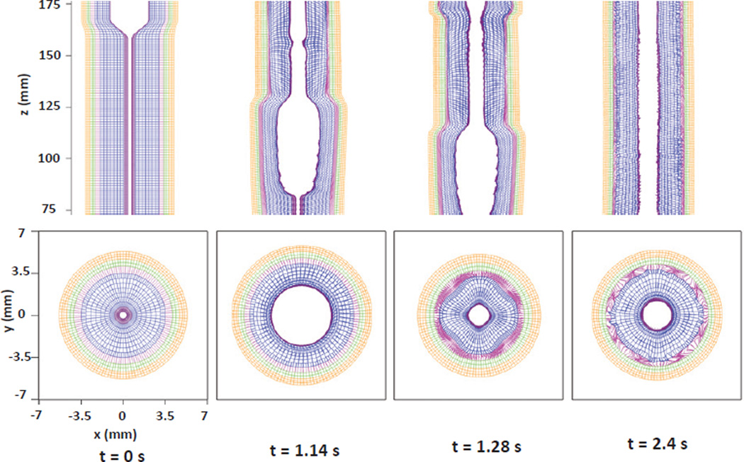
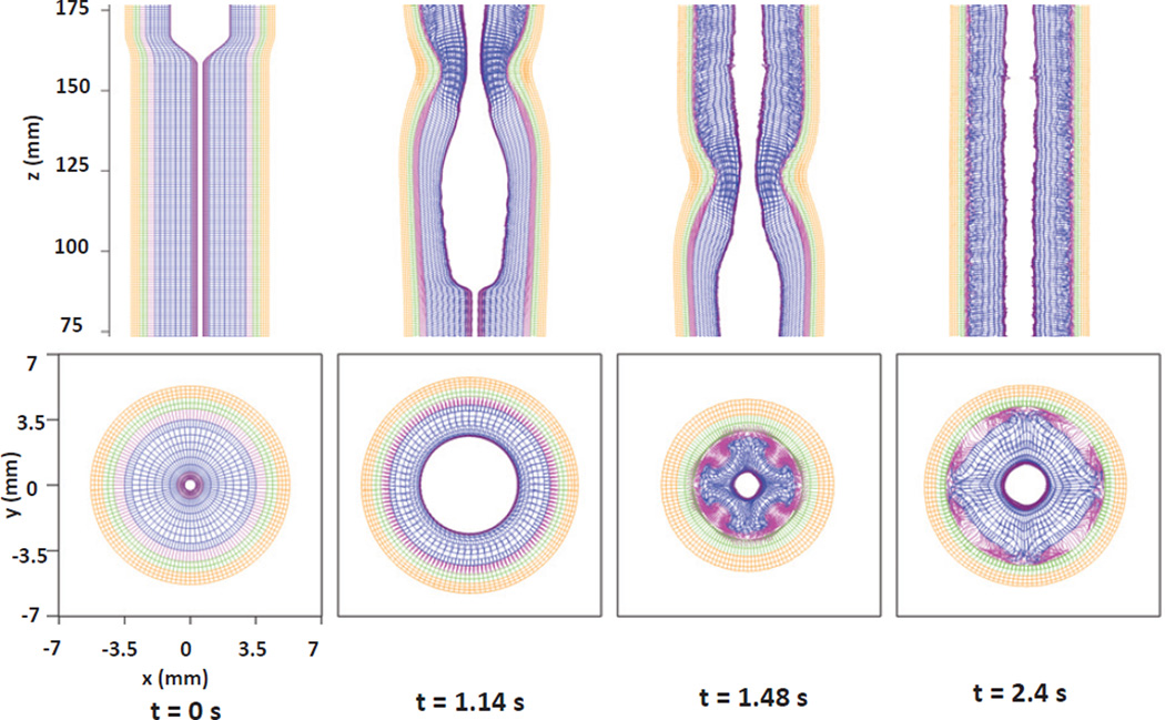
Kinematics of the esophageal layers at four different stages: at rest (t=0 s); at dilation (t=1.14 s); at contraction (t=1.28 s); and at relaxation (t=2.4 s) for Case 1 in Section 5.1. The five layers included in the model, from the inside to the outside, are the IM, OM, IF, CM, and LM layers, respectively. (Upper) Side view of a section of the esophagus within the box: (−7 mm, 7 mm) × (−0.2 mm, 0.2 mm) × (75 mm, 175 mm); (Lower) top view of a section of the esophagus within the box: (−7 mm, 7 mm) × (−7 mm, 7 mm) × (119.5 mm, 120.5 mm). Because of complex kinematics of the esophageal structure, the apparently overlapping or missing springs in the above figures are actually a consequence of out-of-plane motions.
Table 6.
Grid size along (r, θ, z) orientations, denoted as Δr, rΔθ, Δz, for each layer of the esophagus in the reference configuration. Note that the grid size in circumferential orientation rΔθ for each layer should be understood as an average value, since the coordinate r increases from the inner surface to the outer surface.
| Grid size (0.1mm) | IM | OM | IF | CM | LM |
|---|---|---|---|---|---|
| Δr | 2 | 4 | 3 | 3 | 2 |
| rΔθ | 0.5 | 2 | 1.9 | 2.2 | 2.5 |
| Δz | 4 | 8 | 8 | 8 | 8 |
5 Results
5.1 Case 1: Axially-circumferentially-radially arranged mucosal fibers with uniform muscle activation
Here we report a case study of the esophageal transport that considers the mucosal layer to be composed of axially-circumferentially-radially arranged fibers. Experiments show the intact mucosal layer is highly folded at rest (see Fig. 1 in Ref. [8]), so we take the relatively low moduli for circumferential, radial, and axial fibers to be 0.004 kPa, 0.004 kPa, and 0.04 kPa, respectively, to qualitatively capture its effective elastic property. We use uniform activation model as described in eq. (21). The reduction ratio a0 for CM contraction and LM shortening are chosen to be 0.6 and 0.5, respectively. Other parameters are listed in Table 5.
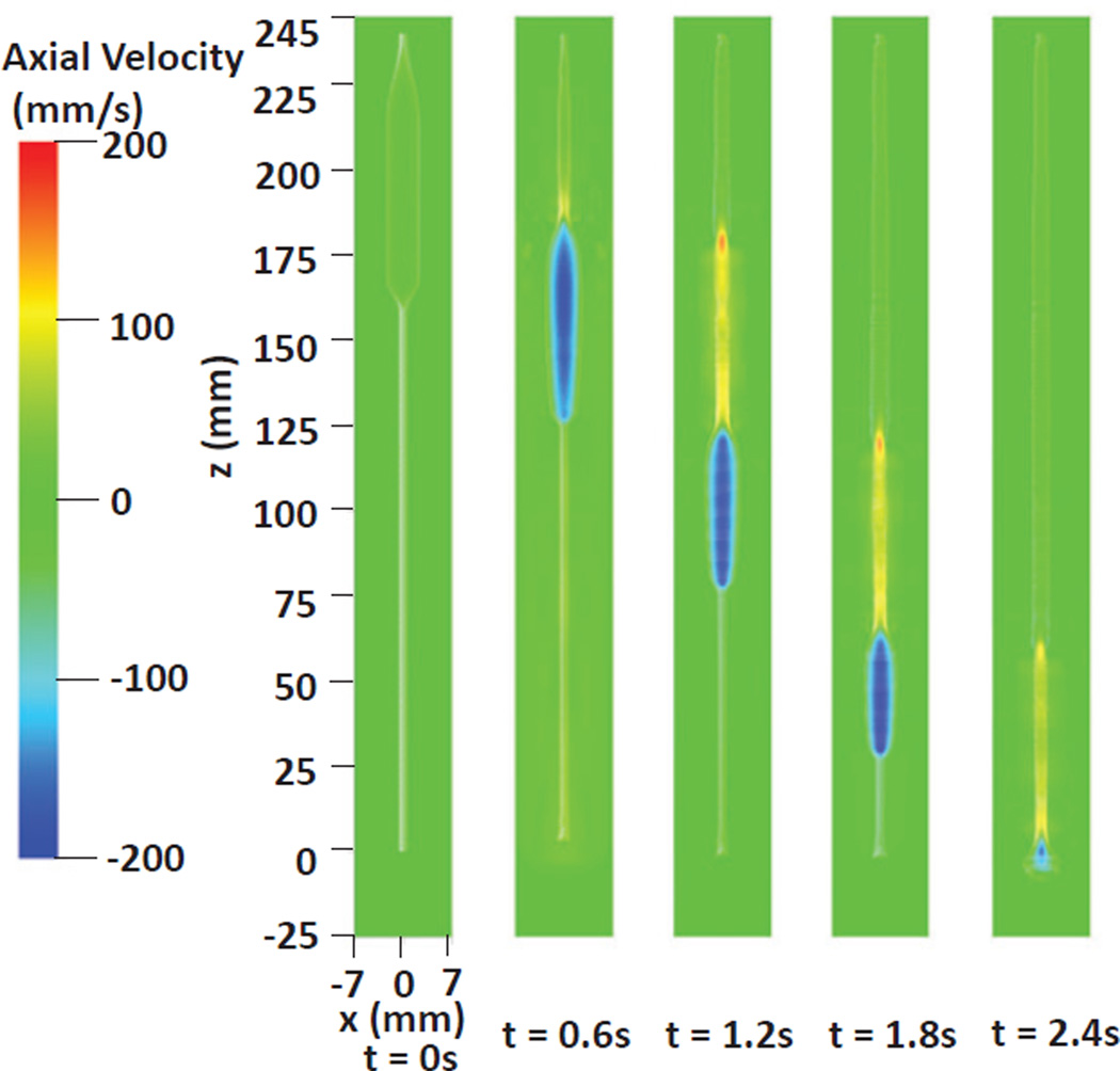
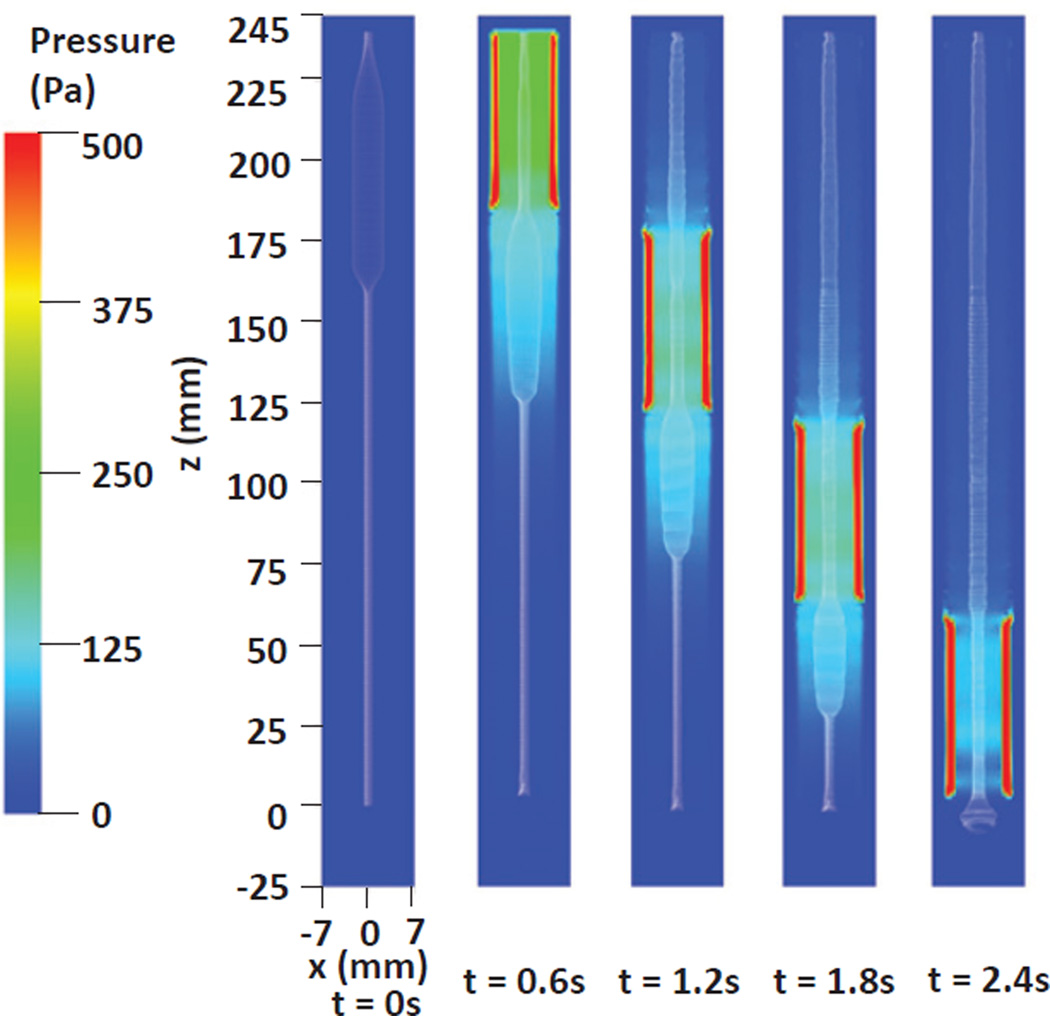
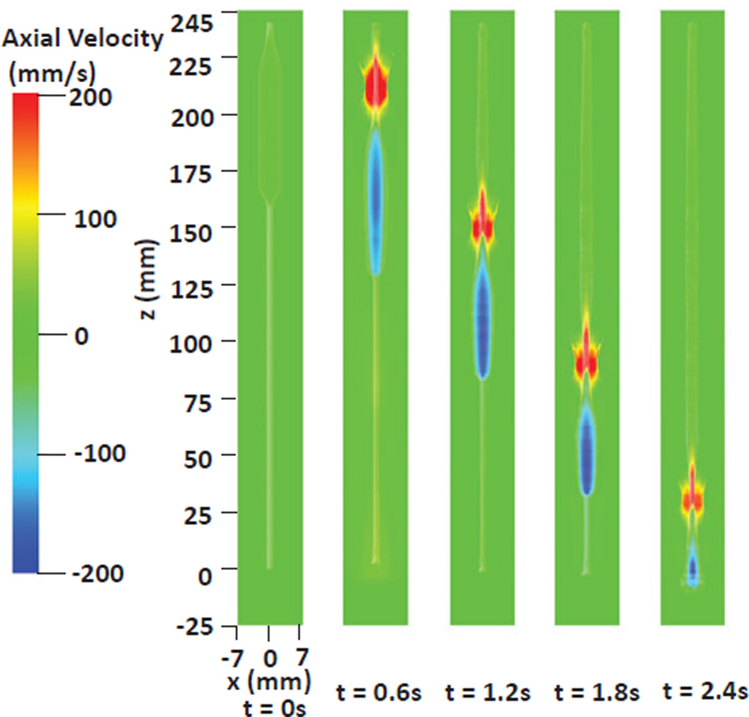
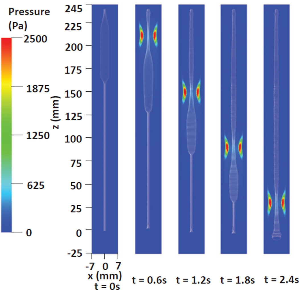
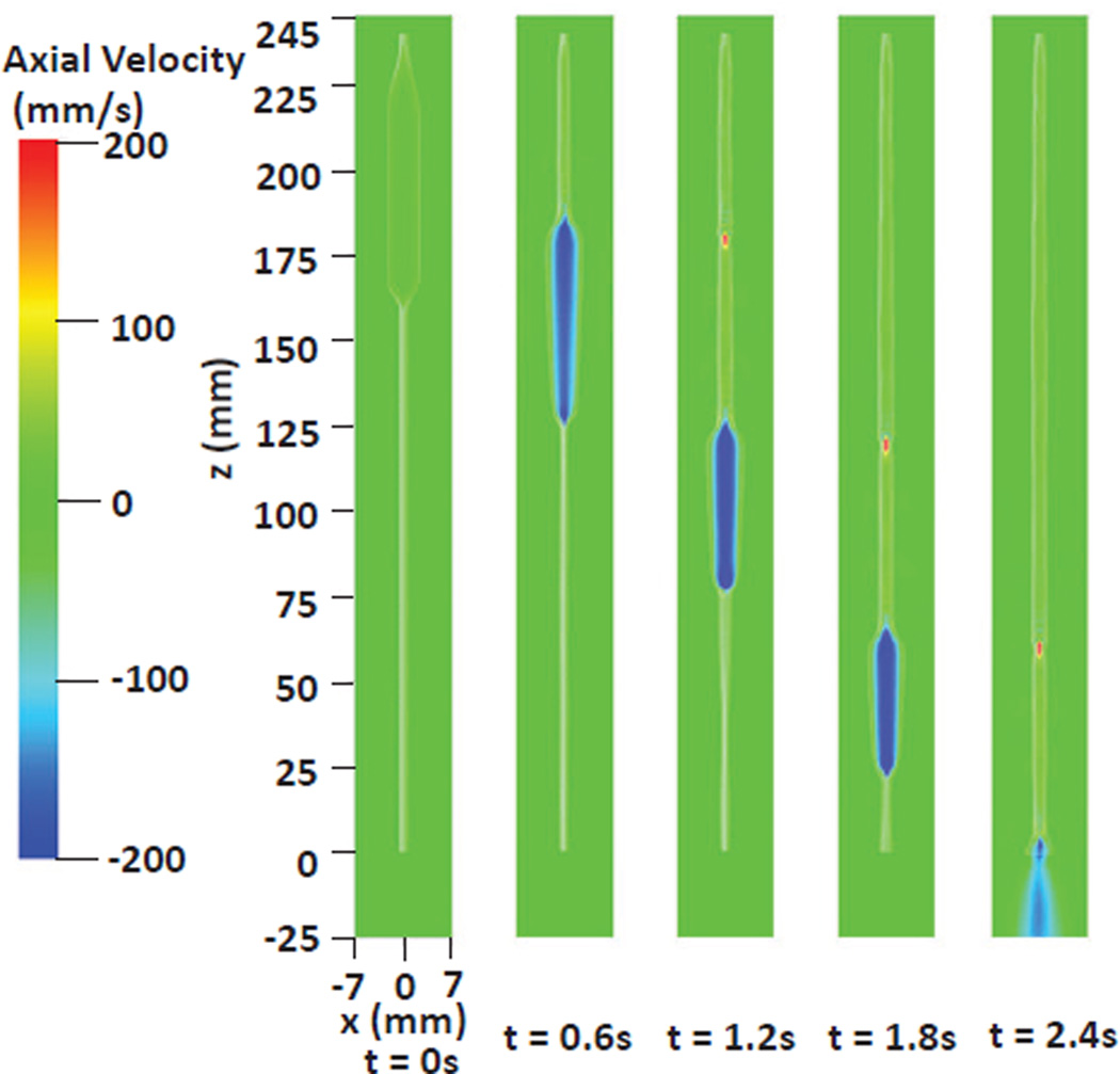
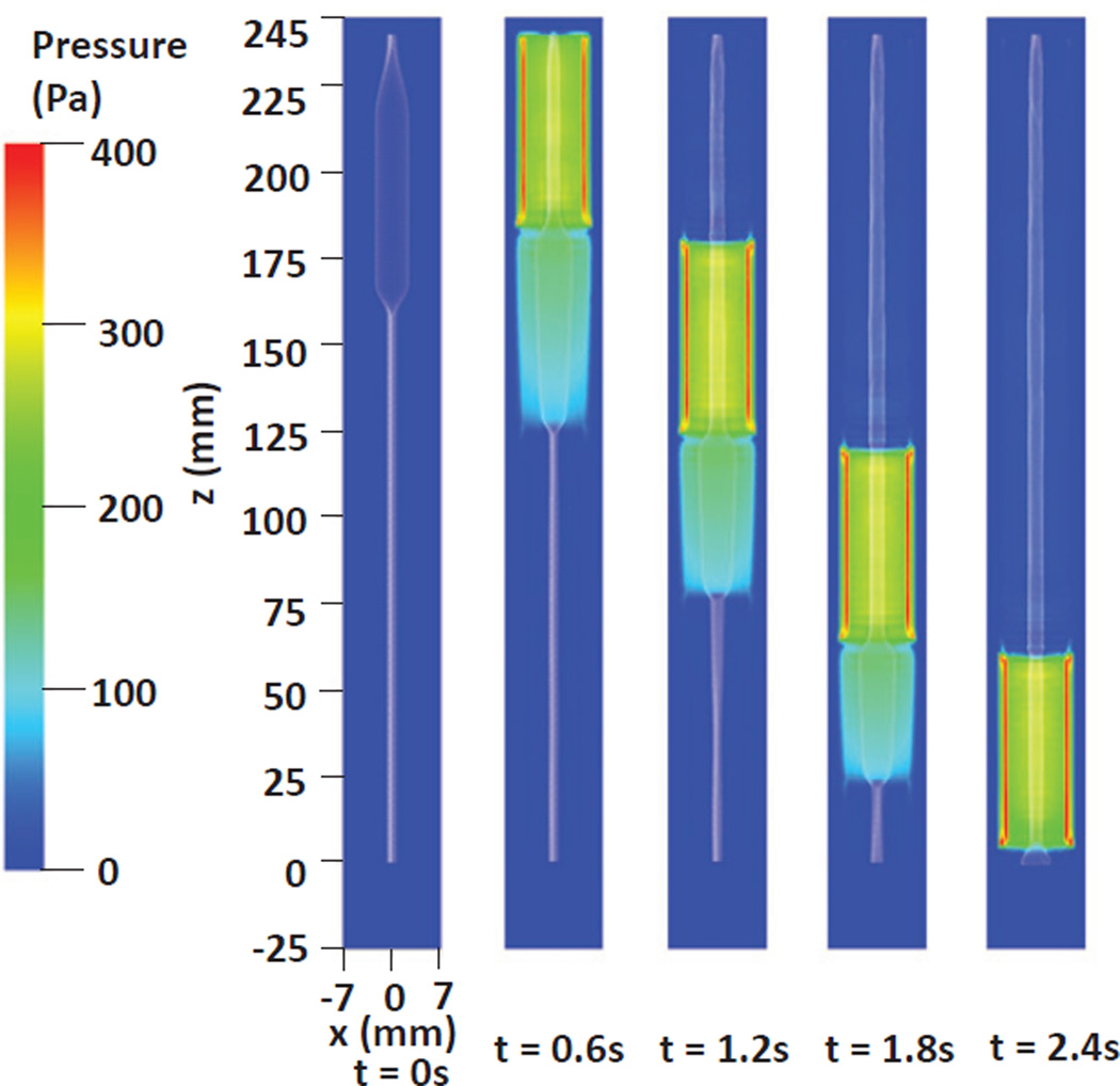
As shown in the Fig. 7, the bolus is transported to and emptied through the bottom of the esophagus in about 2.4 seconds. The running bolus, indicated by the negative axial velocity, is confined by the inner layer of mucosa (IM). This underlines the role of mucosal layers in preparing the tear-drop shape of the bolus. The pressure distribution shown in Fig. 8 implies that the primary pumping force behind the bolus is generated by muscle activation, evidenced by the peak pressure at the contraction region. This is consistent with reported experimental observations [3]. We remark that the “tear-drop” shape of the running bolus is not specified, but rather is a consequence of the fluid-structure-muscle activation interaction. This is different from previous models for bolus transport [4,12,14] where the bolus shape was pre-defined.
Fig. 7.
Axial velocity in the plane y = 0 at different times for Case 1 in Section 5.1. Only the inner layer of mucosa (IM) of the esophagus (white) is shown to better visualize the inside bolus.
Fig. 8.
Pressure in the plane y = 0 at different times for Case 1 in Section 5.1. Only the inner layer of mucosa (IM) of the esophagus (white) is shown to better visualize the inside bolus.
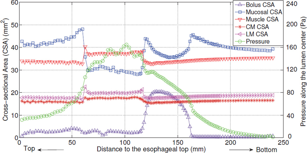
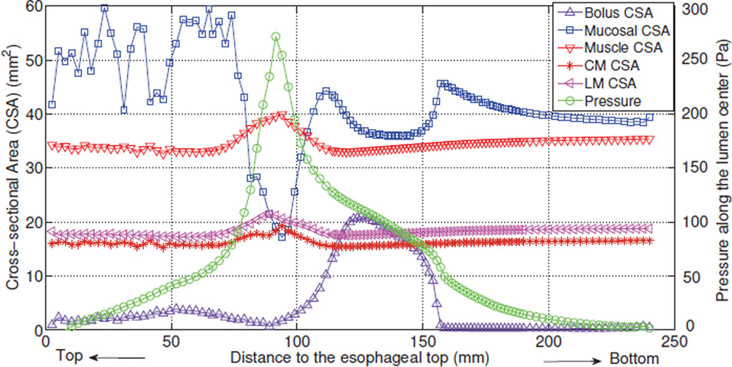
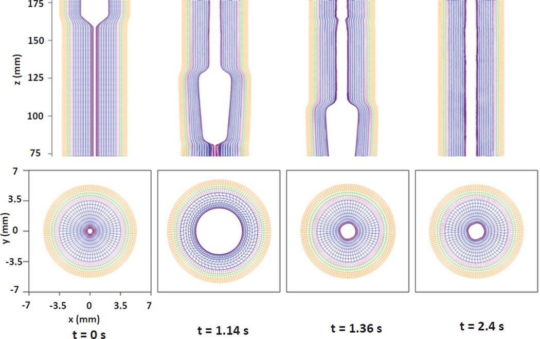
Detailed information on the deformation of each esophageal layer is illustrated in Fig. 9. It can be seen that a typical esophageal segment (at each axial location) passes through four distinct stages: (a) the segment is at rest; (b) the segment is dilated by the incoming bolus; (c) the segment contracts as a result of the incoming activation wave; and (d) the segment relaxes after the activation wave passes. Figs. 7 and 9 show that the mucosal layer plays an important role in the bolus transport. First, mucosal layer shapes the running bolus by dynamically closing (or narrowing) the lumen above the bolus region while opening the lumen from below. Second, the pronounced axial movement of mucosal layer “lubricates” the running bolus, which helps to achieve better transport efficiency. Previous studies on bolus transport excluded mucosal layers, and did not capture this important feature of bolus movement [4,12,14]. Quantitative results for the cross-sectional area (CSA) of the esophageal layers, the bolus, as well as for the pressure distribution along the lumen center at time instant t = 1.2 s are shown in Fig. 10. At the contraction region behind the bolus, a pressure peak and an increased muscle CSA (i.e. the sum of the CSAs of the LM and CM layer) coexist, which is consistent with the experimental observation of Mittal et al. [3].
Fig. 10.
The cross-sectional area (CSA) of the bolus and the esophageal components, and the lumen pressure along its central line: x = 0, y = 0, at t = 1.2 s for Case 1 in Section 5.1.
5.2 Case 2: Axially-circumferentially-radially arranged mucosal fibers with non-uniform muscle activation
In this case, we use the same geometry and material model of esophagus as of Case 1 in Section 5.1, but we use the nonuniform muscle activation model. We take λ as 10 mm for both LM shortening and CM contraction, and we set reduction ratio a0 for CM contraction and LM shortening as 0.6 and 0.5. Other parameters used in the muscle activation model are listed in Table 5. The transport phenomenon is shown in Figs. 11 and 12. It is clear that the nonuniform muscle activation results in more pronounced contraction, as illustrated in Fig. 13. We remark that a distinctive muscle CSA peak overlaps with the pressure peak in this case, as shown in Fig. 14. This is different from Case 1 in Section 5.1, which resulted in a plateau of increased muscle CSA; see Fig. 10. A coexisting muscle CSA and pressure peak is also observed in the clinical test of Mittal et al. [3], which, in conjunction with our simulation, implies that a synchronous nonuniform LM shortening and CM contraction probably corresponds to the normal physiology of esophageal muscle activation.
Fig. 11.
Axial velocity in the plane y = 0 at different times for the Case 2 in Section 5.2. Only the inner layer of mucosa (IM) of the esophagus (white) is shown to better visualize the inside bolus.
Fig. 12.
Pressure in the plane y = 0 at different times for the Case 2 in Section 5.2. Only the inner layer of mucosa (IM) of the esophagus (white) is shown to better visualize the inside bolus.
Fig. 13.
Kinematics of the esophageal layers at four different stages: at rest (t=0 s); at dilation (t=1.14 s); at contraction (t=1.48 s); at relaxation (t=2.4 s), for the Case 2 in Section 5.2. The five layers included in the model, from the inside to the outside, are the IM, OM, IF, CM, and LM layers, respectively. (Upper) Side view of a section of the esophagus within the box: (−7 mm, 7 mm) × (−0.2 mm, 0.2 mm) × (75 mm, 175 mm); (Lower) top view of a section of the esophagus within the box: (−7 mm, 7 mm) × (−7 mm, 7 mm) × (119.5 mm, 120.5 mm).
Fig. 14.
The cross-sectional area (CSA) of the bolus and the esophageal components, and the lumen pressure along its central line: x = 0, y = 0, at t = 1.2 s for Case 2 in Section 5.2.
5.3 Case 3: Helical mucosal fibers with uniform muscle activation
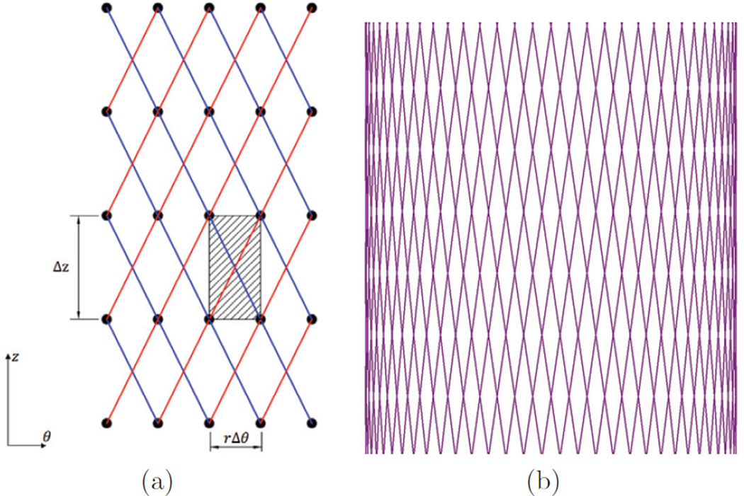
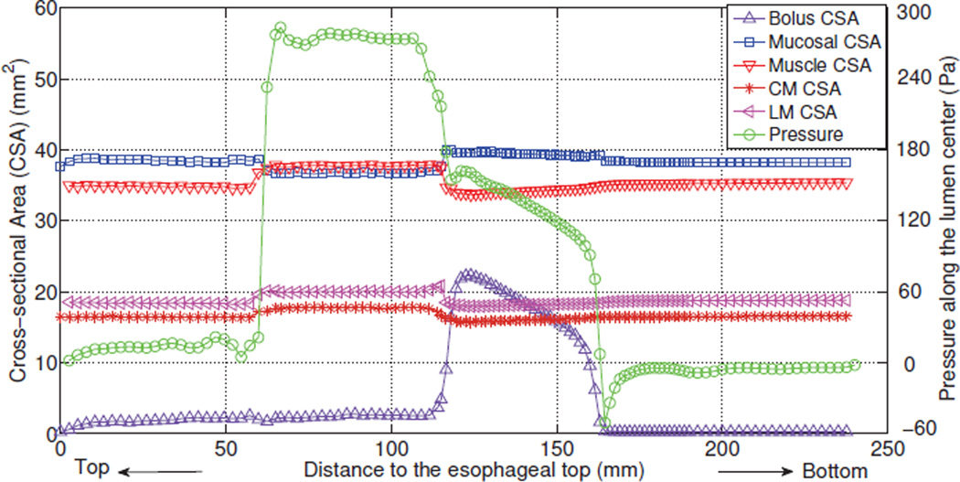
Natali et al. [6] proposed a constitutive model of a multi-layered esophagus, in which the mucosal layer consists of two families of helical fibers, and the muscle layer is composed of axially and circumferentially arranged fibers. Here we present a case with such a helical mucosal fiber arrangement. Two families of helical fibers run in the (r, θ) surfaces, as shown in Fig. 15. Radial springs are used to link the (r, θ) surfaces. The modulus of the helical fibers is taken to be the same as that of fibers in the muscle layer, whereas the modulus of the radial fibers of the mucosal layer are one order of magnitude weaker than the modulus of helical fibers. We use uniform muscle activation model with reduction ratio a0 for CM contraction and LM shortening as 0.5 and 0.3, respectively. Other parameters of muscle activation model are listed in Table 5. Fig. 16 and Fig. 17 shows the bolus transport for this case. A high pressure region exists along the contracting segment, which pushes the bolus down, similar to what is observed in Case 1 in Section 5.1. The details of deformation are illustrated in Fig. 18, which also shows the four distinct stages. However, the deformation pattern is more regular than the previous cases, which may be attributed to the helical configuration of the mucosal layer. As Fig. 17 shows, high pressure and increased muscle CSA overlaps, which indicates a synchrony between CM contraction and LM shortening. No distinct pressure peak exists, however, which is different from results of Case 1 in Section 5.1. This is probably because the helical mucosal layer is less “squeezed”, which is evidenced by the slightly decreased CSA.
Fig. 15.
(a) Schematic of two families of helical fibers and the patch (the hatched area) in (z, θ) surface with radial coordinate r. The patch volume associated with the helical spring of each family is rΔθΔrΔz, if a < r < b; or 0.5rΔθΔrΔz, if r = a or r = b, where a and b are the r-coordinate of the inner surface and outer surface. (b) Illustration of helical fibers running on the inner-most surface of the mucosal layer.
Fig. 16.
Axial velocity in the plane, y = 0 at different times for the Case 3 in Section 5.3. Only the inner layer of mucosa (IM) of the esophagus (white) is shown to better visualize the inside bolus.
Fig. 17.
Pressure field in the plane, y = 0 at different times for the Case 3 in Section 5.3. Only the inner layer of mucosa (IM) of the esophagus (white) is shown to better visualize the inside bolus.
Fig. 18.
Kinematics of the esophageal layers at four different stages: at rest (t=0 s); at dilation (t=1.14 s); at contraction (t=1.36 s); at relaxation (t=2.4 s), for the Case 3 in Section 5.3. The five layers included in the model, from the inside to the outside, are the IM, OM, IF, CM and LM layers, respectively. (Upper) Side view of a section of the esophagus within the box: (−7 mm, 7 mm) × (−0.2 mm, 0.2 mm) × (75 mm, 175 mm); (Lower) top view of a section of the esophagus within the box: (−7 mm, 7 mm) × (−7 mm, 7 mm) × (119.5 mm, 120.5 mm).
6 Remarks on the fiber-based immersed boundary method
In the previous three sub-sections, we showed results for esophageal transport with new insights including roles of mucosal layer and information on lumen pressure and kinematics resulting from the synchrony between CM contraction and LM shortening, in spite of the complexity of the configuration. Here, we add remarks on the application of the classical fiber-based IB method [15] to problems involving significant deformations. First, it is noted that the choice of number of Lagrangian points per Eulerian grid is challenging. Two Lagrangian grid points per Eulerian grid are recommended in each direction to stop the fluid from leaking through the immersed structure [15]. However, the esophagus dilates significantly during the bolus transport. It is important to ensure that there are at least two grid points per Eulerian grid in each direction in the dilated state. This leads to a practical requirement that there should be more than two Lagrangian points per Eulerian grid in each direction in the rest and relaxation state. Increasing Lagrangian grid refinement relative to the Eulerian grid does not necessarily imply higher accuracy, but instead over constrains the system. Hence, we need to verify that the results are reasonable (Fig. 10). The fact that the number of Lagrangian grid points are determined via simulation trials is an undesirable feature.
One remedy, not within the scope of this work, would be to use an adaptive Eulerian mesh, where the adaptive criterion is based on Lagrangian grid spacing. Current adaptive meshing of the Eulerian grid is based on the magnitude of velocity gradients. Another approach could be to have an adaptive Lagrangian discretization such that the number of Lagrangian grid points in the rest and dilated states would differ if the Eulerian grid size is fixed.
The second issue is related to spurious deformations at the scale of the Lagrangian grid. Multiple Lagrangian grid points per Eulerian grid can result in spurious deformation modes at the Lagrangian grid scale. These modes are internal to the Lagrangian grid and thus not resolved by the fluid solution which is at the scale of the Eulerian grid. As a result, in the case of esophageal transport, the relaxed configuration recovered after a bolus has passed has residual deformations at the Lagrangian grid scale. These deformations are pronounced in the compliant mucosal layer.
The third issue pertains to spurious deformations leading to errors in the incompressibility of the Lagrangian structure. The incompressibility constraint is imposed on the Eulerian grid scale. This is not strictly sufficient to impose incompressibility at the Lagrangian grid, which is at a sub-grid scale with respect to the Eulerian grid.
One remedy for both issues two and three is to use a spring configuration with diagonal springs in addition to springs oriented in the three orthogonal directions or to use a helical fiber configuration. Such an approach has been used in prior studies involving swimming of two-dimensional eels [32,40]. Another remedy for these issues could be to use finite element based Lagrangian immersed structure instead of a fiber-based structure [41]. This is being pursued by us but it is not within the scope of this work.
7 Conclusions
In this work, we introduce a method based on the volumetric patch to characterize the elasticity of the immersed fiber-based structure employed in the typical IB method [15,19,21].We first conduct verification studies for flow past a rigid cylinder at Reynolds numbers of 20, 40, and 200. The obtained drag and lift coefficients and Strouhal number of the computed flow are in good agreement with the experimental and numerical data in the literature. We perform a second verification case via comparisons between the computational results and an analytic solution to an idealized tube dilation problem. Low relative errors (5%) are obtained. To study esophageal transport, we develop a fully resolved active musculo-mechanical model that is able to incorporate the liquid bolus, multi-layered esophageal wall, and muscle activation into a unified model. We present three cases of the esophageal transport that differ in the choice of muscle activation model and mucosal fiber arrangement, thereby demonstrating the capabilities and generality of the model. The key feature of bolus transport observed experimentally is a “tear-drop” bolus driven by a muscle contraction wave. This is captured in our simulations. Moreover, new insights are also provided by fully resolved simulations. The simulations show that perfect synchrony between LM shortening and CM contraction leads to an overlap of the high pressure region and an increased muscle CSA. This helps to relate clinical test data from manometry and ultrasound image to the underlying neurally-controlled activity, such as the coordination between CM contraction and LM shortening. Detailed information on kinematics elucidates the role of the mucosal layer in shaping the bolus. Specifically, the mucosal layer provides distensibility to the esophageal lumen, and lubricates the running bolus. We remark that this is the first study that directly looks at the interaction between the bolus and the mucosal layer. Future work should include a parametric study of the effect of changing mucosal property on bolus transport. This will help to understand certain esophageal diseases that are related to the inflammation of the mucosa.
Fig. 19.
The cross-sectional area (CSA) of the bolus and the esophageal components, and the lumen pressure along its central line x = 0 and y = 0, at t = 1.2 s for Case 3 in Section 5.3.
Acknowledgements
The support of grant R01 DK079902 (J.E.P.) and R01 DK056033 (P.J.K.) from the National Institutes of Health, USA is gratefully acknowledged. B.E.G. acknowledges research support from the National Science Foundation (NSF awards DMS-1016554 and ACI-1047734).
Appendix A: Analysis of a fiber-based tube dilation problem
Here we derive eq. (20) for the tube dilation problem presented in Section 3.2. The governing equations for an incompressible fluid are
| (23) |
| (24) |
in which σf is the fluid stress, u is the fluid velocity, ρ is the fluid density, μ is the fluid viscosity, and p is the pressure imposing the incompressibility constraint. For a neutrally buoyant incompressible viscoelastic structure, the governing equations are
| (25) |
| (26) |
in which σe is the stress tensor in the elastic structure, pe is the pressure that imposes the incompressibility constraint in the elastic structure and σ̄ is the unknown deviatoric part of the elasticity tensor. Continuity of traction and velocity at the fluid-solid interface implies
| (27) |
in which n denotes the outward normal vector to the structure interface. This equation implies that there is generally a pressure discontinuity at the fluid-structure interface. For the dilation problem at steady state, eq. (23) implies a uniform pressure in the tube, denoted as Pinner, because the inertial and viscous terms vanish. Thus, eq. (27) becomes
| (28) |
For the fiber-based structure, let R and r denote the initial and deformed radial coordinates, respectively, at each material point. At the boundaries of the tube, let Ri and Ro denote the initial inner and outer radius, and ri and ro denote the current inner and outer radius, respectively. Then we can obtain the relationship: R = R(r), based on volume conservation and plain-strain deformation:
| (29) |
The elasticity of the fiber-based tube is represented by three families of springs in circumferential, radial, and axial directions. In the (r, θ) plane, only deviatoric stresses along the radial and circumferential orientations are nonzero,
| (30) |
| (31) |
Here, Sr and Sθ are the moduli of radial and circumferential fibers, respec tively. At steady state, the inertial term in the momentum equations of fluid and structure vanishes, and ∇ · σe = 0. Therefore, along the r-direction we obtain
| (32) |
This gives us the equation for pe as
| (33) |
We impose zero-traction boundary condition on the four lateral surfaces of the fluid domain. At steady state, this implies that the exterior fluid pressure is zero, so that traction continuity at the exterior fluid-solid interface implies,
| (34) |
The solution to eq. (33) for pe with the boundary condition given by eq. (34) is
| (35) |
The inner pressure, Pinner is obtained from eq. (28) as
| (36) |
Under dilation and in the absence of shearing motions, the radial fibers will become compressed. For compression-resistant fibers such as those used in this model, this is an unstable configuration, and the minimum energy configuration is obtained when the layers of the tube rotate to release the energy of compression. In this configuration, the radial fibers do not contribute to the elastic stress. Therefore, by letting Sθ = S and Sr = 0, the fluid pressure at the inner surface ri becomes
| (37) |
Substituting eq. (29) into eq. (37), we obtain the explicit form of Pinner as
| (38) |
Here , ri = Ri + U(ri), U(ri) denotes the radial displacement of the inner surface of the tube, and .
Footnotes
Publisher's Disclaimer: This is a PDF file of an unedited manuscript that has been accepted for publication. As a service to our customers we are providing this early version of the manuscript. The manuscript will undergo copyediting, typesetting, and review of the resulting proof before it is published in its final citable form. Please note that during the production process errors may be discovered which could affect the content, and all legal disclaimers that apply to the journal pertain.
Contributor Information
Wenjun Kou, Theoretical and Applied Mechanics, Northwestern University, 2145 Sheridan Road, Evanston, Illinois 60208, USA.
Amneet Pal Singh Bhalla, Department of Mechanical Engineering, Northwestern University, 2145 Sheridan Road, Evanston, Illinois 60208, USA; Courant Institute of Mathematical Sciences, New York University, New York, NY 10012, USA.
Boyce E. Griffith, Department of Mathematics, University of North Carolina at Chapel Hill, Phillips Hall, Campus Box 3250, Chapel Hill, North Carolina 27599-3250, USA
John E. Pandolfino, Department of Medicine, Feinberg School of Medicine, Northwestern University, 676 North Saint Clair Street, 14th Floor, Chicago, Illinois 60611, USA
Peter J. Kahrilas, Department of Medicine, Feinberg School of Medicine, Northwestern University, 676 North Saint Clair Street, 14th Floor, Chicago, Illinois 60611, USA
Neelesh A. Patankar, Department of Mechanical Engineering, Northwestern University, 2145 Sheridan Road, Evanston, Illinois 60208, USA.
References
- 1.Heil M, Hazel AL. Fluid-structure interaction in internal physiological flows. Annual Review of Fluid Mechanics. 2011;43:141–162. [Google Scholar]
- 2.Pouderoux P, Lin S, Kahrilas PJ. Timing, propagation, coordination, and effect of esophageal shortening during peristalsis. Gastroenterology. 1997;112(4):1147–1154. doi: 10.1016/s0016-5085(97)70125-2. [DOI] [PubMed] [Google Scholar]
- 3.Mittal RK, Padda B, Bhalla V, Bhargava V, Liu JM. Synchrony between circular and longitudinal muscle contractions during peristalsis in normal subjects. American Journal of Physiology-Gastrointestinal and Liver Physiology. 2006;290(3):G431–G438. doi: 10.1152/ajpgi.00237.2005. [DOI] [PubMed] [Google Scholar]
- 4.Li M, Brasseur JG. Non-steady peristaltic transport in finite-length tubes. Journal of Fluid Mechanics. 1993;248:129–129. [Google Scholar]
- 5.Fan Y, Gregersen H, Kassab GS. A two-layered mechanical model of the rat esophagus. experiment and theory. BioMedical Engineering OnLine. 2004;3(1):40. doi: 10.1186/1475-925X-3-40. [DOI] [PMC free article] [PubMed] [Google Scholar]
- 6.Natali AN, Carniel EL, Gregersen H. Biomechanical behaviour of oesophageal tissues: Material and structural configuration, experimental data and constitutive analysis. Medical Engineering & Physics. 2009;31(9):1056–1062. doi: 10.1016/j.medengphy.2009.07.003. [DOI] [PubMed] [Google Scholar]
- 7.Sokolis DP. Structurally-motivated characterization of the passive pseudo-elastic response of esophagus and its layers. Computers in Biology and Medicine. 2013;43(9):1273–1285. doi: 10.1016/j.compbiomed.2013.06.009. [DOI] [PubMed] [Google Scholar]
- 8.Yang W, Fung TC, Chian KS, Chong CK. 3D mechanical properties of the layered esophagus: experiment and constitutive model. Journal of Biomechanical Engineering. 2006;128(6):899–908. doi: 10.1115/1.2354206. [DOI] [PubMed] [Google Scholar]
- 9.Yang W, Fung TC, Chian KS, Chong CK. Directional, regional, and layer variations of mechanical properties of esophageal tissue and its interpretation using a structure-based constitutive model. Journal of Biomechanical Engineering. 2006;128(3):409–418. doi: 10.1115/1.2187033. [DOI] [PubMed] [Google Scholar]
- 10.Stavropoulou EA, Dafalias YF, Sokolis DP. Biomechanical and histological characteristics of passive esophagus: Experimental investigation and comparative constitutive modeling. Journal of Biomechanics. 2009;42(16):2654–2663. doi: 10.1016/j.jbiomech.2009.08.018. [DOI] [PubMed] [Google Scholar]
- 11.Li M, Brasseur JG, Dodds WJ. Analyses of normal and abnormal esophageal transport using computer simulations. American Journal of Physiology-Gastrointestinal and Liver Physiology. 1994;266(4 Pt 1):G525–G543. doi: 10.1152/ajpgi.1994.266.4.G525. [DOI] [PubMed] [Google Scholar]
- 12.Ghosh SK, Kahrilas PJ, Zaki T, Pandolfino JE, Joehl RJ, Brasseur JG. The mechanical basis of impaired esophageal emptying postfundoplication. American Journal of Physiology-Gastrointestinal and Liver Physiology. 2005;289(1):G21–G35. doi: 10.1152/ajpgi.00235.2004. [DOI] [PubMed] [Google Scholar]
- 13.Ghosh SK, Kahrilas PJ, Brasseur JG. Liquid in the gastroesophageal segment promotes reflux, but compliance does not: a mathematical modeling study. American Journal of Physiology-Gastrointestinal and Liver Physiology. 2008;295(5):G920–G933. doi: 10.1152/ajpgi.90310.2008. [DOI] [PMC free article] [PubMed] [Google Scholar]
- 14.Nicosia MA, Brasseur JG. A mathematical model for estimating muscle tension in vivo during esophageal bolus transport. Journal of Theoretical Biology. 2002;219(2):235–255. doi: 10.1006/jtbi.2002.3118. [DOI] [PubMed] [Google Scholar]
- 15.Peskin CS. The immersed boundary method. Acta numerica. 2002;11:479–517. [Google Scholar]
- 16.Peskin CS. Flow patterns around heart valves: A numerical method. Journal of Computational Physics. 1972;10(2):252–271. [Google Scholar]
- 17.Peskin CS. Numerical analysis of blood flow in the heart. Journal of Computational Physics. 1977;25(3):220–252. [Google Scholar]
- 18.Mittal R, Iaccarino G. Immersed boundary methods. Annual Review of Fluid Mechanics. 2005;37:239–261. [Google Scholar]
- 19.Griffith BE. Immersed boundary model of aortic heart valve dynamics with physiological driving and loading conditions. International Journal for Numerical Methods in Biomedical Engineering. 2012;28(3):317–345. doi: 10.1002/cnm.1445. [DOI] [PubMed] [Google Scholar]
- 20.Fai TG, Griffith BE, Mori Y, Peskin CS. Immersed boundary method for variable viscosity and variable density problems using fast constant-coefficient linear solvers i: Numerical method and results. SIAM Journal on Scientific Computing. 2013;35(5):B1132–B1161. [Google Scholar]
- 21.Griffith BE. An accurate and efficient method for the incompressible navier-stokes equations using the projection method as a preconditioner. Journal of Computational Physics. 2009;228(20):7565–7595. [Google Scholar]
- 22.Chadwick RS. Mechanics of the left-ventricle. Biophysical Journal. 1982;39(3):279–288. doi: 10.1016/S0006-3495(82)84518-9. [DOI] [PMC free article] [PubMed] [Google Scholar]
- 23.Ohayon J, Chadwick RS. Effects of collagen microstructure on the mechanics of the left-ventricle. Biophysical Journal. 1988;54(6):1077–1088. doi: 10.1016/S0006-3495(88)83044-3. [DOI] [PMC free article] [PubMed] [Google Scholar]
- 24.Tozeren A. Continuum rheology of muscle-contraction and its application to cardiac contractility. Biophysical Journal. 1985;47(3):303–309. doi: 10.1016/S0006-3495(85)83920-5. [DOI] [PMC free article] [PubMed] [Google Scholar]
- 25.Griffith BE, Hornung RD, McQueen DM, Peskin CS. An adaptive, formally second order accurate version of the immersed boundary method. Journal of Computational Physics. 2007;223(1):10–49. [Google Scholar]
- 26.Lai MC, Peskin CS. An immersed boundary method with formal second-order accuracy and reduced numerical viscosity. Journal of Computational Physics. 2000;160(2):705–719. [Google Scholar]
- 27.Taira K, Colonius T. The immersed boundary method: A projection approach. Journal of Computational Physics. 2007;225(2):2118–2137. [Google Scholar]
- 28.Tritton DJ. Experiments on the flow past a circular cylinder at low reynolds numbers. Journal of Fluid Mechanics. 1959;6:547–567. [Google Scholar]
- 29.Dennis SCR, Chang G-Z. Numerical solutions for steady flow past a circular cylinder at reynolds numbers up to 100. Journal of Fluid Mechanics. 1970;42(03):471–489. [Google Scholar]
- 30.Linnick MN, Fasel HF. A high-order immersed interface method for simulating unsteady incompressible flows on irregular domains. Journal of Computational Physics. 2005;204(1):157–192. [Google Scholar]
- 31.Liu C, Zheng X, Sung CH. Preconditioned multigrid methods for unsteady incompressible flows. Journal of Computational Physics. 1998;139(1):35–57. [Google Scholar]
- 32.Bhalla APS, Bale R, Griffith BE, Patankar NA. A unified mathematical framework and an adaptive numerical method for fluid-structure interaction with rigid, deforming, and elastic bodies. Journal of Computational Physics. 2013;250(0):446–476. [Google Scholar]
- 33.Griffith BE, Peskin CS. On the order of accuracy of the immersed boundary method: Higher order convergence rates for sufficiently smooth problems. Journal of Computational Physics. 2005;208(1):75–105. [Google Scholar]
- 34.Kahrilas PJ. The anatomy and physiology of dysphagia. In: Gelfand DW, Richter JE, editors. Dysphagia, Diagnosis, and Treatment. New York: Igaku-Shoin; 1989. pp. 11–28. [Google Scholar]
- 35.Gregersen H, Kassab GS, Fung YC. The zero-stress state of the gastrointestinal tract: biomechanical and functional implications. Digestive diseases and sciences. 2000;45(12):2271–2281. doi: 10.1023/a:1005649520386. [DOI] [PubMed] [Google Scholar]
- 36.Dooley CP, Schlossmacher B, Valenzuela JE. Effects of alterations in bolus viscosity on esophageal peristalsis in humans. American Journal of Physiology-Gastrointestinal and Liver Physiology. 1988;254(1 Pt 1):G8–G11. doi: 10.1152/ajpgi.1988.254.1.G8. [DOI] [PubMed] [Google Scholar]
- 37.Dantas RO, Kern MK, Massey BT, Dodds WJ, Kahrilas PJ, Brasseur JG, Cook IJ, Lang IM. Effect of swallowed bolus variables on oral and pharyngeal phases of swallowing. American Journal of Physiology-Gastrointestinal and Liver Physiology. 1990;258(5 Pt 1):G675–G681. doi: 10.1152/ajpgi.1990.258.5.G675. [DOI] [PubMed] [Google Scholar]
- 38.Meyer GW, Austin RM, r Brady CE, Castell DO. Muscle anatomy of the human esophagus. Journal of Clinical Gastroenterology. 1986;8(2):131–134. doi: 10.1097/00004836-198604000-00005. [DOI] [PubMed] [Google Scholar]
- 39.Puckett JL, Bhalla V, Liu J, Kassab G, Mittal RK. Oesophageal wall stress and muscle hypertrophy in high amplitude oesophageal contractions. Neurogastroenterology & Motility. 2005;17(6):791–799. doi: 10.1111/j.1365-2982.2005.00693.x. [DOI] [PubMed] [Google Scholar]
- 40.Tytell ED, Hsu C-Y, Williams TL, Cohen AH, Fauci LJ. Interactions between internal forces, body stiffness, and fluid environment in a neuromechanical model of lamprey swimming. Proceedings of the National Academy of Sciences. doi: 10.1073/pnas.1011564107. [DOI] [PMC free article] [PubMed] [Google Scholar]
- 41.Griffith BE, Luo X. Hybrid finite difference/finite element version of the immersed boundary method. Submitted, preprint available from http://www.cims.nyu.edu/~griffith. [Google Scholar]


