

Abstract
Emulsification is a powerful, well-known technique for mixing and dispersing immiscible components within a continuous liquid phase. Consequently, emulsions are central components of medicine, food and performance materials. Complex emulsions, including multiple emulsions and Janus droplets which contain hemispheres of differing material, are of increasing importance1 in pharmaceuticals and medical diagnostics2, in the fabrication of microparticles and capsules3–5 for food6, in chemical separations7, in cosmetics8, and in dynamic optics9. Because complex emulsion properties and functions are related to the droplet geometry and composition, the development of rapid, simple fabrication approaches allowing precise control over the droplets’ physical and chemical characteristics is critical. Significant advances in the fabrication of complex emulsions have been made using a number of procedures, ranging from large-scale, less precise techniques that give compositional heterogeneity using high-shear mixers and membranes10, to small-volume but more precise microfluidic methods11,12. However, such approaches have yet to create droplet morphologies that can be controllably altered after emulsification. Reconfigurable complex liquids potentially have greatly increased utility as dynamically tunable materials. Here we describe an approach to the one-step fabrication of three- and four-phase complex emulsions with highly controllable and reconfigurable morphologies. The fabrication makes use of the temperature-sensitive miscibility of hydrocarbon, silicone and fluorocarbon liquids, and is applied to both the microfluidic and the scalable batch production of complex droplets. We demonstrate that droplet geometries can be alternated between encapsulated and Janus configurations by varying the interfacial tensions using hydrocarbon and fluorinated surfactants including stimuli-responsive and cleavable surfactants. This yields a generalizable strategy for the fabrication of multiphase emulsions with controllably reconfigurable morphologies and the potential to create a wide range of responsive materials.
Phase separation approaches using mass transfer of a co-solvent or separating agent13–16 have attracted interest as simplified routes to the fabrication of complex emulsions. In designing our new method, we use the facts that fluorocarbons are lipophobic as well as hydrophobic and that many fluorocarbon and hydrocarbon liquids are immiscible at room temperature but have a low upper consolute temperature (Tc) and mix with gentle heating17. Hexane and perfluorohexane, for example, have a Tc of 22.65 °C (ref. 18). Our interest in fluorocarbons and their emulsions was also based on the fact that they are inert materials with unique properties that have been exploited for use as magnetic resonance imaging and ultrasound contrast agents, as artificial blood, in water-repellent surfaces, and in the acoustically triggered release of payloads17,19,20. To explore the feasibility of using a temperature-induced phase separation route to complex emulsions (Fig. 1a), we emulsified a 1:1 volume ratio of hexane and perfluorohexane above Tc in an aqueous solution of Zonyl FS-300 (hereafter ‘Zonyl’), which is a nonionic fluorosurfactant with the linear chemical formula RfCH2CH2O(CH2CH2O)xH. Cooling below Tc induced phase separation and yielded structured complex droplets (Fig. 1b). These complex emulsions were readily produced in bulk by shaking warm hexane–perfluorohexane liquid in a surfactant solution (Fig. 1c). Although these droplets were polydisperse, the morphology and composition of the droplets were highly uniform. Chemical partitioning during phase separation14 gave directed compartmentalization of solutes (Fig. 1d). Therefore, temperature-induced phase separation of liquids provides a simple, scalable approach to the fabrication of complex functional emulsions.
Figure 1. Temperature-controlled phase separation of hydrocarbon and fluorocarbon liquids can be used to create complex emulsions.

a, Complex emulsion fabrication. b, Above Tc, hexane and perfluorohexane are miscible and emulsified in aqueous 0.1% Zonyl (top left). Below Tc, hexane and perfluorohexane phases separate to create a hexane-in-perfluorohexane-in-water (H/F/W) double emulsion (bottom right). Hexane is dyed red. Scale bar, 200 μm. c, Emulsions of uniform composition made by bulk emulsification (such as shaking). Scale bar, 100 μm. d, Lateral confocal cross-section of H/F/W double-emulsion droplets. Hydrocarbon-soluble Nile Red dye (green) selectively extracts into hexane. Rhodamine B dyes the aqueous phase (red). Scale bar, 100 μm. Monodisperse droplets in b and d were made using a microcapillary device.
The morphology of the complex droplets is exclusively controlled by interfacial tension. To put this in an analytical context, consider a complex emulsion of any immiscible liquids F and H (at a given volume ratio) in a third immiscible liquid W. We choose the interfacial tensions of the H–W interface, γH, the F–W interface, γF, and the F–H interface, γFH, such that γF and γH are significantly larger than γFH. This regime is relevant to combinations of liquids H and F that have low interfacial tension just below Tc. It can be shown21 that these multiphase droplets are nearly spherical in shape and will adopt one of the following three thermodynamically permissible internal configurations: (1) liquid H completely encapsulates liquid F, (2) liquids H and F form a Janus droplet, and (3) liquid F completely encapsulates liquid H (Fig. 2a). These droplet configurations are characterized by two contact angles, θH between the H–W and F–H interfaces, and θF between the F–H and F–W interfaces. The three interfacial tensions acting along the interfaces must be in equilibrium for the droplet configuration to be stable, as can be expressed by the following equations:
| (1) |
| (2) |
Figure 2. Reconfiguration of droplet morphology is dynamic and results from changes in the balance between interfacial tensions.
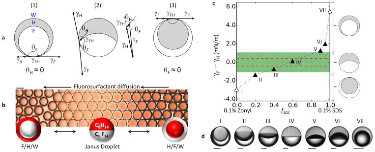
a, Sketch of the effect of interfacial tensions on the configuration of a complex droplet. In (1), γF > γH + γFH, favouring encapsulation of phase F within phase H. In (3), γH > γF + γFH and phase H is encapsulated within phase F. At intermediate values of γF and γH, a Janus droplet with geometry typified by (2) is formed. γF, γH and γFH can be reconfigured into a Neumann triangle29 solvable for θH and θF. b, Hexane–perfluorohexane droplets reconfigure in response to variation in the concentration of Zonyl as it diffuses through 0.1% SDS from right (high Zonyl concentration) to left (low Zonyl concentration). Scale bar, 100 μm. c, Configurational stability diagram for the hexane–perfluorohexane–water system showing γF – γH as a function of the fraction of 0.1% SDS, fSDS, where the other fraction is 0.1% Zonyl. The green band denotes the region |γF – γH| < γFH = 1.07 ± 0.1 mN m−1, obtained from geometrical analysis of Janus droplets. The red dashed lines correspond to γFH = 0.4 mN m−1 as predicted for a temperature of 10 °C (ref. 23), the approximate temperature at which the droplets in d were imaged. Filled and unfilled triangles indicate conditions under which Janus droplets and double emulsions were observed, respectively. Labels I–VII correspond to the droplets in d. d, Optical micrographs of hexane–perfluorohexane droplets in solutions of 0.1% Zonyl and 0.1% SDS in varying ratios as plotted in c. Hexane is dyed and appears grey. Scale bars, 50 μm.
Figure 2a shows that configurations (1) and (3) are the limiting cases of configuration (2) as θH → 0 and θF → 0, respectively. Equations (1) and (2) can be used to translate these limiting contact angles into interfacial tension conditions, yielding the following two relationships:
| (3) |
| (4) |
Recast as the difference between γH and γF, equations (3) and 4 indicate that when γF – γH ≥ γFH the droplets assume configuration (1) in Fig. 2a. Conversely, when γH – γF ≥ γFH the droplets adopt configuration (3) in Fig. 2a. However, when the difference between γH and γF is of the order of γFH, the droplets adopt a Janus droplet geometry associated with configuration (2) in Fig. 2a.
These physical relationships reveal that, given a low value of γFH, only slight changes in the balance of γH and γF are necessary to induce dramatic changes in the droplet’s morphology. We proposed that if liquids F, H, and W were fluorocarbon, hydrocarbon and water, respectively, dynamic reconfiguration of the droplets might be triggered by hydrocarbon and fluorinated surfactants22. Consistently, a 1:1 volume mixture of hexane and perfluorohexane in 0.1% Zonyl generated hexane-in-perfluorohexane-in-water (H/F/W) double emulsions (Fig. 1), indicating a preferential decrease in γF. In comparison, emulsification of the same hexane–perfluorohexane mixture in water containing 0.1% sodium dodecyl sulphate (SDS, an anionic hydrocarbon surfactant), yielded F/H/W double emulsions as a result of a preferentially decreased γH. When we introduced a small volume of 10% Zonyl into F/H/W droplets in 0.1% SDS, we observed that the droplet morphology dynamically changed in accordance with the concentration gradient of Zonyl. Droplets first passed through a spherical Janus drop morphology before inverting to H/F/W double emulsions (Fig. 2b and Supplementary Video 1). The reverse was seen when concentrated SDS was added to 0.1% Zonyl-stabilized droplets (Supplementary Video 2). These results suggest that not only is droplet morphology highly controllable on initial emulsification by the choice of surfactants, but that these emulsions are also dynamically and reversibly reconfigurable by changing the balance of γF and γH.
To validate the proposed dynamic mechanism, we measured the tensions of hexane–water (γH) and perfluorohexane–water (γF) interfaces for a variety of 0.1% SDS and 0.1% Zonyl ratios using the pendant-drop method (Methods, Extended Data Fig. 1 and Extended Data Table 1). The perfluorohexane–hexane interfacial tension, γFH, has been estimated previously23 and is in general agreement with our γFH estimates based on geometrical analysis of the Janus drops produced (Methods, Extended Data Fig. 2 and Extended Data Table 2). We can use the quantity γF – γH as a simple indicator of droplet configuration, and this quantity is plotted as a function of surfactant ratio in Fig. 2c. When only 0.1% SDS was used (fSDS = 1), we measured γF – γH > γFH and observed complete encapsulation of perfluorohexane by hexane. In a mixed SDS–Zonyl composition, the trajectory entered the narrow green zone (Fig. 2c) corresponding to |γF – γH| < γFH. Within this Janus droplet configurational zone, the droplet morphology began to ‘flip’ as visualized in Fig. 2d. As the proportion of 0.1% SDS approached zero and fluorosurfactant dominated, the trajectory left the Janus zone and the droplets assumed a configuration in which hexane was encapsulated by perfluorohexane. Overall, the observed droplet geometries closely followed the predicted morphological trend and confirm that variations in hydrocarbon and fluorinated surfactants are effective for the manipulation of the balance between γF and γH.
This understanding has made it possible for us to induce droplet morphological transitions with stimuli-responsive and cleavable surfactants (Fig. 3a). Responsive surfactants24 undergo reversible changes in their effectiveness25 when triggered by stimuli such as magnetic fields, pH, CO2 or light. To create optically sensitive droplets, we synthesized a light-responsive surfactant26 consisting of an azobenzene moiety that reversibly undergoes a photo-induced isomerization between a more effective trans configuration and a less effective cis configuration (Fig. 3b). When this surfactant was used in combination with Zonyl, we observed that the hexane–perfluorohexane droplets rapidly and reversibly changed morphology in response to ultraviolet (wavelength, λ = 365 nm) and blue (λ = 470 ± 20 nm) light. Depending on the relative concentrations of Zonyl and the light-responsive surfactant and on the length of exposure to light, we tuned the morphology to switch between the double-emulsion and Janus states or to invert entirely (Supplementary Videos 3 and 4). Analogous results were achieved with Zonyl and a pH-responsive surfactant, N-dodecylpropane-1,3-diamine, by alternating the pH between values above and below the surfactant’s lowest pKa value, 4.7 (ref. 27; Fig. 3c). Similarly, cleavable surfactants show a reduction in efficacy when irreversibly degraded by exposure to light, heat or changes in pH. In this context, we demonstrated irreversible transition between the F/H/W and H/F/W double-emulsion states (Fig. 3d) using an acid-cleavable surfactant28, sodium 2,2-bis(hexyloxy)propyl sulphate, in conjunction with Zonyl. The results shown here demonstrate the versatility of the complex fluorous–hydrocarbon droplets’ response to a wide range of stimuli.
Figure 3. Emulsions reconfigure in response to light and pH.

a, Sketch of how the variations in γF and γH induced by alterations in the effectiveness of a hydrocarbon surfactant translate into differences in drop morphology on a phase-stability diagram. Grey represents hexane and white represents perfluorohexane. b, Chemical structure of the light-responsive surfactant which reversibly isomerizes under ultraviolet (UV) and blue light between the more effective trans form of the surfactant (left) and the less effective cis form (right). Aligned beneath are optical micrographs of hexane–perfluorohexane emulsions that are tuned to undergo specific morphological transitions in response to light. Hexane is dyed red, and the aqueous phase consists of Zonyl and the light-responsive surfactant pictured. Top: droplets undergo complete inversion. Middle: F/H/W double-emulsion drops transition to Janus droplets. Most droplets are viewed from the top, but one is lying on its side allowing a view of the droplet profile. Bottom: Janus droplets transition to an H/F/W double emulsion. Scale bar, 100 μm. c, A pH-responsive surfactant, N-dodecylpropane-1,3-diamine, is used in combination with Zonyl to create pH-responsive droplets. Acid diffuses through the solution from right (high concentration) to left (low concentration), reducing the pH below pKa = 4.7 and so generating a less effective surfactant30 and inducing inversion of the hexane–perfluorohexane emulsions. Scale bar, 100 μm. d, Emulsions stabilized by a combination of Zonyl and acid-cleavable surfactant, sodium 2,2-bis(hexyloxy)propyl sulphate28, undergo morphological changes as the cleavable surfactant is degraded over time at pH = 3. Scale bar, 50 μm.
Liquid droplets and solid particles with asymmetric properties were created by effecting different chemistries in the separate compartments of a fluorous–hydrocarbon Janus droplet. To create directionally orientable and movable liquid Janus droplets, we synthesized magnetic Fe3O4 nanoparticles stabilized with oleic acid for preferential partitioning into the hydrocarbon hemisphere. Janus droplets with hemispheres of ethyl nonafluorobutyl ether (the fluorous phase) and dichlorobenzene with Fe3O4 (the hydrocarbon phase) were rapidly oriented and moved in the direction of a magnet (Fig. 4a). To generate solid hemispherical particles, we polymerized an emulsion consisting of a liquid polymer precursor, 1,6-hexanediol diacrylate, as the hydrocarbon phase and methoxyperfluorobutane as the fluorous phase (Fig. 4b). By replacing methoxyperfluorobutane with a fluorinated acrylate oligomer and crosslinker, we created spherical solid Janus particles with fluorinated and non-fluorinated sides (Fig. 4c).
Figure 4. Magnetic complex emulsions, complex emulsions as templates and four-phase emulsions.

a, Janus droplets of ethyl nonafluorobutyl ether and dichlorobenzene containing magnetite nanoparticles in the dichlorobenzene phase are oriented with a magnet. Scale bar, 200 μm. b, Scanning electron micrograph of hemispherical particles made from photopolymerized Janus droplets containing hexanediol diacrylate and methoxyperfluorobutane. Scale bar, 100 μm. c, Top: scanning electron micrograph of a Janus particle with hydrocarbon and fluorinated polymeric hemispheres. Bottom: the energy-dispersive X-ray spectral map reveals the fluorinated hemisphere. Scale bar, 50 μm. d, Four-phase emulsions reconfigure in response to changes in interfacial tension. Drops contain hydrocarbon oil (H, mineral oil with octadecane), silicone oil (Si) and fluorinated oil (F, ethyl nonafluorobutyl ether) emulsified in water (W). The silicone phase is enriched with a fraction of the two other phases. Left: 1% Zonyl generates an H/Si/F/W triple emulsion. Right: 1% SDS generates an F/Si/H/W triple emulsion with a thin outer shell. Phases were identified with fluorescent dyes. Nile Red (green) preferentially dyes the hydrocarbon oil, and fluorous-tagged coumarin dye31 preferentially dyes the fluorous phase (blue). Scale bars, 50 μm.
The same principles of droplet transformations observed in three-phase emulsions were extended to a four-phase system, thereby generating reconfigurable droplets of even higher-order complexity. We designed a system comprised of silicone oil (Si), hydrocarbon oil (H, mineral oil and octadecane) and fluorinated oil (F, ethyl nonafluorobutyl ether) such that the liquids mixed when heated and separated into three phases at room temperature (20°C). Systematically varying ratios of 1% Zonyl and 1% SDS aqueous surfactant solutions caused droplets to assume morphologies combining both Janus configurations (indicated using ‘|’) and encapsulated configurations (indicated using ‘/’) (Fig. 4d). For example, a triple emulsion H/Si/F/W was formed in 1% Zonyl, but in a 3:2 ratio of 1% Zonyl:1% SDS we observed a Janus configuration between the fluorous and silicone phases while the hydrocarbon phase remained encapsulated in the silicone phase, H/Si|F/W. As the proportion of SDS increased, the droplet passed through Janus droplet and mixed Janus–encapsulated droplet configurations before inverting to the reverse triple emulsion (F/Si/H/W) in 1% SDS.
Complex droplets of controllable composition and dynamic reconfigurable morphology provide a new active element for novel and existing applications of emulsions. The fabrication method and the dynamic mechanism presented are general and can be broadly applied using a wide variety of chemicals, materials and surfactants well beyond the initial demonstrations described here. Droplets triggered by environmental stimuli could be used, for example, to target the release of drugs at tumours, to induce changes in colour or transparency for camouflage, as vehicles for the sequestration of pollutants, as tunable lenses, or as sensors. Emulsions with the characteristic ability to selectively ‘present’ and ‘hide’ specific liquid interfaces and controllably alter droplet morphology and symmetry will find abundant applications.
METHODS
Chemicals
The following chemicals were used as received: sodium dodecyl sulphate (≥99%), Sudan Red 7B (95%), 1,6-hexanediol diacrylate (80%), 1,4-butanediol diacrylate (90%), trimethylolpropane ethoxylate triacrylate (Mn = 428 g mol−1), 1,2-dichlorobenzene (99%), Zonyl FS-300 (40% solids), methoxyperfluorobutane (99%), mineral oil (light), iron(II) chloride tetrahydrate (99.99%), 2,2,3,3,4,4,5,5,6,6,7,7,8,8,9,9-hexadecafluorodecane-1,10-diol (97%), methacrylic acid (99%) and octadecane (99%) (Sigma-Aldrich); silicone oil (for oil baths −40 to +200 °C), perfluorohexanes (98%), hexanes (98%), and iron(III) chloride (98%) (Alfa Aesar); ethyl nonafluorobutyl ether (>98%) and sodium oleate (>97%) (TCI); Darocur 1173 (Ciba); fluorinated acrylate oligomer (Sartomer); Nile Red (99%) (Acros); N-dodecylpropane-1,3-diamine (>95%) (Matrix). Light-responsive surfactant was made by the literature procedure26,32. Fluorinated coumarin dye was made by the literature procedure31. Cleavable surfactant sodium 2,2-bis(hexyloxy)propyl sulphate was made by the literature procedure28.
Synthesis of the fluorinated crosslinker
To synthesize the fluorinated crosslinker 2,2,3,3,4,4,5,5,6,6,7,7,8,8,9,9-hexadecafluorodecane-1,10-diyl bis(2-methylacrylate), a mixture of 2,2,3,3,4,4,5,5,6,6,7,7,8,8,9,9-hexadecafluorodecane-1,10-diol (10 g, 22 mmol, 1 equiv.), methacrylic acid (20 ml, 240 mmol, 11 equiv.), 2,6-di-tert-butyl-4-methylphenol (200 mg, 0.9 mmol, 0.04 equiv.) and sulphuric acid (0.1 ml, 18 M) in toluene (250 ml) was heated to reflux with azeotropic removal of water (Dean–Stark trap). After three days, the mixture was cooled to room temperature and washed with saturated sodium bicarbonate (3 × 300 ml). The toluene was dried with MgSO4 and evaporated. The remaining residue/product was dissolved in perfluorohexanes (150 ml) and filtered. The filtrate was evaporated to yield 7.81 g of colourless liquid (13.1 mmol, 61% yield). 1H-NMR (400 MHz, CDCl3): δ 6.22 (p, J = 1.1 Hz, 2H), 5.70 (p, J = 1.5 Hz, 2H), 4.65 (t, J = 13.3 Hz, 4H), 1.98 (t, J = 1.3 Hz, 6H). 13C-NMR (101 MHz, CDCl3): δ 165.8, 135.0, 127.9, 117.5–107.5 (m, CF2), 60.1 (t, J = 27.3 Hz), 18.1. 19F-NMR (376 MHz, CDCl3): δ −119.3 (p, J = 13.3 Hz, 4F), −121.8–−122.0 (m, 8F), −123.3 (bs, 4F). LRMS (EI): calculated for C18F14F18O4 [M]+, 598; found, 598. NMR spectra were obtained on a Bruker Avance 400 MHz spectrometer. LRMS was acquired on an Agilent 5973N GCMS. Please see Extended Data Fig. 3 and Extended Data Fig. 4 for reaction scheme and NMR spectra.
General fabrication of complex emulsions
The hydrocarbon and fluorocarbon liquids of choice were heated until miscible and emulsified. The temperature required varied depending on the solutions. Solutions were emulsified either in bulk by shaking or by coaxial glass capillary microfluidics and cooled to induce phase separation. For hexane–perfluorohexane emulsions, the emulsions were chilled on ice before imaging and often imaged while immersed in a cool water bath to maintain a temperature below 20 °C. For microfluidics, Harvard Apparatus PHD Ultra syringe pumps were used to inject the outer phase and inner phase using a glass capillary microfluidic device made from an outer square capillary (outer diameter, 1.5 mm; inner diameter, 1.05 mm; AIT Glass) and inner cylindrical capillary (outer diameter, 1 mm; World Precision Instruments) pulled to a 30 μm tip using a P-1000 Micropipette Puller (Sutter Instrument Company). The microfluidic set-up was heated above the Tc of the inner phase solution using a heat lamp. Emulsions were then cooled below Tc to induce phase separation. Emulsions were observed to be stable during the time periods used (of the order of days). Longer-term stability experiments were not conducted.
Measurement of interfacial tensions
Interfacial tension measurements were made using the pendant-drop method (ramé-hart Model 500 Advanced Goniometer). Measurements on a drop were taken every 5 s until the interfacial tension appeared to be nearing equilibrium or the droplet became unstable. The hexane–water interfacial tension was measured to be 50 mN m−1 and the perfluorohexane–water interfacial tension was measured to be 55 mN m−1.
Microscopy
Lateral confocal cross-sections of the droplets were imaged using a Nikon 1AR ultrafast spectral scanning confocal microscope. Scanning electron microscopy was conducted on gold-sputtered samples with a JEOL 6010LA scanning electron microscope. Fluorescence and bright-field images were taken with a Zeiss Axiovert 200 inverted microscope equipped with a Zeiss AxioCam HRc camera. Droplets typically orient themselves with the denser, fluorous phase downward. To take side-view images of the drops, emulsions were shaken to induce the drops to roll around while images were made with a 1 ms exposure.
Fabrication of magnetic Janus droplets
Magnetite nanoparticles were made as follows: 25 ml of concentrated NH3OH was added to an acidified solution of 1.6 g of FeCl3 and 1 g of FeCl2·4H2O in 50 ml of water at 80 °C. The magnetite nanoparticle precipitate was collected with a magnet, washed with water and redispersed. One gram of sodium oleate in 10 ml of water was added while stirring at room temperature. The oily black precipitate was extracted with hexanes. The solid was collected by evaporation of solvent, and was subsequently redispersed in dichlorobenzene. Janus droplets were obtained by heating the nanoparticle–dichlorobenzene solution and ethyl nonafluorobutyl ether above Tc and shaking in 0.2% SDS and 0.2% Zonyl in a 2.5:1 ratio. The drops were oriented using a neodymium magnet.
Fabrication of light-responsive emulsions
Hexane dyed with Sudan Red 7b and perfluorohexane in equal volumes were used as the inner phase, and a mixture of 0.1% light-sensitive surfactant and 0.1% Zonyl FS-300 in an 8:2 ratio was used as surfactants in the aqueous phase. Slight adjustments to the surfactant concentrations were made during imaging to tune the droplet morphological transitions to achieve the desired outcome; for example, more Zonyl was needed to generate droplets that transitioned from a Janus droplet to a hexane–perfluorohexane–water double emulsion. A mercury lamp was used as the intense light source, and DAPI and FITC filters were used to selectively allow ultraviolet (λ = 365 nm) and blue (λ = 470 ± 20 nm) light to reach the sample while imaged on an inverted microscope.
Fabrication of reversibly responsive pH-sensitive emulsions
Hexane and perfluorohexane in equal volumes were emulsified in a solution of 2 mM N-dodecylpropane-1,3-diamine and 1.2% Zonyl in 0.2 M NaCl. Salt solution was used to control for effects of ionic strength on the emulsion morphology. The pH was adjusted to above and below pH 4.7 by addition of HCl and NaOH.
Fabrication of emulsions using an acid-cleavable surfactant
Hexane and perfluorohexane in equal volumes were emulsified in a solution of 0.3% sodium 2,2-bis(hexyloxy)propyl sulphate and 0.4% Zonyl in 0.1 M NaCl. The pH was adjusted to 3 using HCl and the solution was allowed to sit undisturbed on the inverted microscope stage while images were periodically made over an hour.
Fabrication of hemispherical particles
1–6,hexanediol diacrylate with 4% Darocur 1173 photo-initiator was heated with an equal volume of methoxyperfluorobutane above Tc and emulsified. 1% SDS and 1% Zonyl in a 3:2 ratio yielded Janus droplets which were then polymerized under a Dymax Blue Wave 200 ultraviolet lamp while kept cold on ice.
Fabrication of fluorous–hydrocarbon Janus particles
Fluorinated acrylate oligomer, fluorinated crosslinker, 1,4-butanediol diacrylate and trimethylolpropane ethoxylate triacrylate were used in a volume ratio of 15:3:14:10. 5% Darocur 1173 was used as the photo-initiator. The inner phase mixture was heated above Tc, emulsified in 1% SDS and polymerized with ultraviolet light over ice.
Fabrication of four-phase emulsions
Light mineral oil with 20 wt% octadecane (used to reduce Tc in a mixture with the other liquids), silicone oil and ethyl nonafluorobutyl ether were used as the inner phases in a volume ratio of 6:7:13. The mineral oil and ethyl nonafluorobutyl ether both partition into the silicone oil such that on phase separation the silicone oil phase is enriched with some quantity of the two other phases. Aqueous mixtures of varying ratios of 1% Zonyl and 1% SDS were used as the outer phase, and emulsions were formed in bulk by shaking.
Estimation of equilibrium interfacial tensions in the presence of surfactants
Experimentally, it proved difficult to measure the interfacial tensions with the pendant-drop method accurately for very long periods of time while maintaining a stable drop volume because surfactant continued to adsorb at the droplet interface, further reducing the already low interfacial tensions. Therefore, it is likely that the final interfacial tensions, γ̂, recorded for the hexane–water interface and, respectively, the perfluorohexane–water interface for different surfactant compositions, fSDS, as illustrated in Extended Data Fig. 1a, are not the equilibrium interfacial tensions, γeqb, for that system. In the absence of additional experimental data for long time scales, we used theories of dynamic interfacial tension to estimate γeqb.
Rosen suggested33 that the dynamic interfacial tension of surfactants could be accurately modelled using an empirical model of the form
| (5) |
where γ0 = γ(t = 0) and t* and n are positive, empirically determined constants. The value of n depends on the type of surfactant and the interface considered, as well as on the concentration of the surfactant, and must therefore be independently determined for every set of experimental conditions. The constant t* is the half-life of the interfacial tension decay process—it is the time taken for the difference, Δγ = γ(t) − γeqb to decrease to half its initial value. The three unknown model parameters (γeqb, t* and n) can be determined from a least-squares fit of equation (5) to the experimental dynamic interfacial tension data. The measure of the ‘goodness-of-fit’ of equation (5) to the experimental data is quantified by the coefficient of determination, or R2, value34. The closer this value is to 1, the better the fit.
An example of the fit of the model to the dynamic interfacial tension data is shown in red in Extended Data Fig. 1a. The parameter results of using equation (5) to fit the interfacial tension data for all the surfactant systems considered are presented in Extended Data Table 1. The smallest value of R2 obtained for the experimental data across all the systems studied was 0.909, indicating very good agreement between the predictions made using equation (5) and the experimental data generated using the goniometer.
The resulting extracted values of γeqb have been used to plot the variation in the interfacial tensions γH and γF as a function of the 0.1% SDS fraction, fSDS, in Fig. 2 and Extended Data Fig. 1b. We note that some droplets fall just outside the designated Janus region. Discrepancies may be due to our inability to measure and estimate the equilibrium interfacial tensions with the 0.1 mN m−1 accuracy required, or there may be slight mixing of hexane and perfluorohexane in the droplets, which would alter the interfacial tensions relative to those of the pure liquids.
Estimation of γFH from the analysis of Janus droplet images
Bulk mixtures of hexane and perfluorohexane have an upper consolute temperature, Tc, of approximately 22 °C, with a critical density of 1.14 g cm−3 and a volume ratio very close to 1:1 (ref. 18). The interfacial tension of the hexane–perfluorohexane interface at temperatures close to (but below) this upper consolute temperature is close to zero, and, consequently, it is difficult to measure accurately using conventional laboratory techniques such as pendant-drop or Du Nuoy ring tensiometry. The best estimate in the physical chemistry literature comes from the predictions of a model for capillary fluctuations at an interface fitted to X-ray reflectivity measurements23. In ref. 23 it is proposed that the variation in the interfacial tension γFH (in units of mN m−1) with temperature T (in units of K) is given by
| (6) |
Equation (6) predicts that at a temperature of 283.15 K (10 °C), the hexane–perfluorohexane interfacial tension should be 0.4 mN m−1. We were unable to find other experimental data in the literature to support this estimate. However, given the equilibrium interfacial tension values and images of the resulting Janus droplets, it was possible to also estimate γFH for our system.
The relationships between the shapes of Janus droplets and the ratio of the volumes of the two constituent phases, k, and the relative magnitudes of the interfacial tensions operating at the various interfaces of the droplet have been examined in ref. 21. The theoretical treatment there can be used to relate the radii of curvature of the F–H, H–W and F–W interfaces to the volume ratio and the interfacial tensions γH, γF and γFH:
| (7) |
Given the interfacial tension values at the H–W and F–W interfaces (γH and γF, respectively), equation (7) can be used to determine γFH if we can independently calculate the three radii of curvature RH, RF and RFH.
The shape of a typical hexane–perfluorohexane Janus droplet in water is illustrated in Extended Data Fig. 2a. The droplet’s interfaces are spherical arcs with different radii of curvature (denoted by RH, RF and RFH). Furthermore, the line of contact between the two phases on the outer (water-facing) surface of the droplet is a circle whose diameter, D, is indicated by the dotted line in Extended Data Fig. 2a, b. The droplet in Extended Data Fig. 2a can be deconstructed into three spherical caps of the type shown in Extended Data Fig. 2b, each with the same base—a circle of diameter D—and respective radii RH, RF and RFH. The volumes of these three spherical caps are denoted by Vcap(RH, D), Vcap(RF, D) and Vcap(RFH, D), respectively.
From the definition of the volume ratio, k, between the hexane and perfluorohexane phases, it follows that:
| (8) |
The volume of a spherical cap, Vcap(r, d), can be calculated using the principles of elementary three-dimensional geometry35. Knowledge of the values of k, RH, RF and D allows us to solve equation (8) for the radius of curvature of the F–H interface, RFH. Equation (7) can then be used to solve for the missing interfacial tension, γFH.
The two radii of curvature, RH and RF, and the diameter, D, of the circle of contact can be computed by analysing the images of the Janus droplets. A schematic of the analysis process is shown in Extended Data Fig. 2c–e. A raw image of a Janus droplet (Extended Data Fig. 2c) is first subjected to the Canny edge-detection algorithm36 based on the non-normalized contrast, with a Gaussian kernel radius of 2.0 and low and high thresholds of 2.0 and 7.0, respectively. This procedure results in the detection of the outer (water-facing) interfaces of the Janus droplet as shown in Extended Data Fig. 2d. Arcs corresponding to the H–W and F–W interfaces are then selected by visual inspection and fitted to circles using Taubin’s algorithm37. These arcs and their fitted circles are depicted as blue and red circles (with green dots for centres) in Extended Data Fig. 2e. The radii of these two circles correspond to the radii of curvature, RH and RF, of the H–W and F–W interfaces, respectively. The diameter, D, of the circle of contact between the hexane and perfluorohexane phases is calculated as the minimum separation between the points lying between the arcs chosen to represent the H–W and F–W interfaces. This line of minimum separation is shown in Extended Data Fig. 2e. Image preprocessing and edge detection were performed in ImageJ v1.48, and the circle-fitting and interfacial tension calculation was performed in MATLAB.
This droplet analysis was performed for six Janus droplets, three from each of the two conditions fSDS = 0.4 and fSDS = 0.6. The interfacial tensions obtained are tabulated in Extended Data Table 2. The values of γFH do not vary significantly between the two sets of surfactant systems, which is consistent with our expectation that γFH is at best only weakly affected by the composition of the surfactant. The average value of γFH deduced from this analysis is 1.07 ± 0.1 mN m−1.
We note that accurately determining the interfacial tensions through the radii of curvature of the interfaces of the droplet is feasible only in the absence of fluid flow around the complex emulsion droplets. The presence of such a flow, even at low shear rates, leads to a deformation of the surface area of the droplet, causing local gradients in surfactant concentration and inducing Marangoni stresses38. The interplay between these effects ultimately determines the interfacial tensions at any point on a complex emulsion droplet. Higher shear rates can dramatically disrupt droplet stability, leading to the fragmentation of the complex emulsion and the release of the encapsulated phases—a phenomenon whose onset has been examined in detail by theoretical39 and experimental40 studies.
Extended Data
Extended Data Figure 1. Dynamic interfacial tension data was used to estimate the equilibrium interfacial tensions for the hexane–water and perfluorohexane–water interfaces.
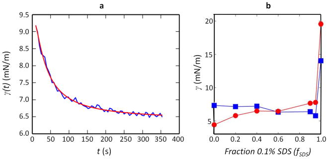
a, Dynamic interfacial tension data (in blue) was obtained from the pendant-drop method; the representative data shown here was measured for the hexane–water interface at fSDS = 0.9 (such that the aqueous solution contained 0.1% SDS and 0.1% Zonyl in a 9:1 ratio). The data was fitted to an empirical model (in red) to estimate the equilibrium value of the interfacial tension γeqb = γ(t → ∞). Such fitting was performed for all measured interfacial tensions and the fitted parameter results are tabulated in Extended Data Table 1. b, The estimated equilibrium interfacial tension values were used to plot the hexane–water (squares) and perfluorohexane–water (circles) interfacial tensions as a function of the fraction of 0.1% SDS, fSDS, where the other fraction is 0.1% Zonyl. See discussion in Methods section for more details.
Extended Data Figure 2. The geometry of a Janus droplet can be used to estimate the interfacial tension between hydrocarbon and fluorocarbon internal phases.
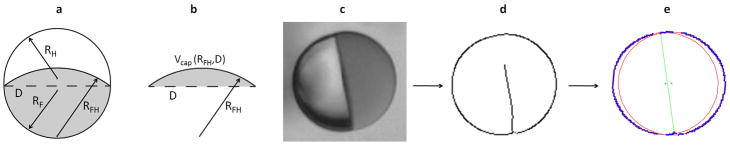
a, Sketch of a Janus droplet consisting of hydrocarbon (grey) and fluorocarbon (white) phases within an aqueous outer phase. The radii of curvature of the H–W (RH), F–W (RF) and F–H (RFH) interfaces are related to their respective interfacial tensions through the Young–Laplace equation. The diameter of the circle of contact between the two phases (dashed line) is denoted as D. b, The Janus droplet is composed of three spherical caps, and the volume, Vcap, of each constituent spherical cap is a function of the radius of curvature of the spherical surface and the base diameter D. Here we show the cap at the intersection of the hydrocarbon and fluorocarbon phases in which Vcap is a function of RFH and D. c, An exemplary image of a hexane–perfluorohexane Janus droplet obtained at fSDS = 0.6, which was used to estimate RFH and, in turn, γFH. d, The droplet pictured in c is subjected to edge detection to determine the H–W and F–W interfaces. e, The resulting edges are fitted to circles (red lines with green centres). The diameter of the circle of contact is then computed (green line). Given the ratio of the volumes of the two phases, we then determined the radius of curvature, RFH, of the hexane–perfluorohexane interface, which was subsequently used to estimate γFH. See discussion in the Methods section for more details and Extended Data Table 2 for estimated values of γFH.
Extended Data Figure 3. Synthesis scheme and 1H-NMR of fluorinated crosslinker.

a, Reaction scheme for the synthesis of the fluorinated crosslinker. b, 1H-NMR spectrum of the fluorinated crosslinker.
Extended Data Figure 4. 13C-NMR and 19F-NMR of the fluorinated crosslinker.

a, 13C-NMR spectrum of the fluorinated crosslinker. b, 19F-NMR of the fluorinated crosslinker.
Extended Data Table 1. Parameter values obtained by fitting an empirical model to interfacial tension measurements obtained using pendant-drop goniometry.
Dynamic interfacial tension data were fitted to a model (discussion in Methods) to estimate equilibrium interfacial tension values. The parameters obtained from the fitting are presented here. The larger the value of the characteristic time, t*, the slower the decay of the interfacial tension to its equilibrium value, γeqb. The value of R2 is a measure of how well the model fits the experimental data. For all the data used in this study, R2 was above 0.9, signifying a good fit.
| 0.1% SDS fraction (fSDS) | Hexane-Water Interface | Perfluorohexane-Water Interface | ||||
|---|---|---|---|---|---|---|
|
| ||||||
| γeqb (mN/m) | t* (s) | R2 | γeqb (mN/m) | t* (s) | R2 | |
| 0.00 | 7.33 ± 0.12 | 156 ± 24 | 0.925 | 4.42 ± 0.14 | 159 ± 42 | 0.980 |
| 0.20 | 7.15 ± 0.03 | 337± 15 | 0.989 | 5.80± 0.04 | 106±5 | 0.979 |
| 0.40 | 7.21 ±0.14 | 315 ± 53 | 0.956 | 6.49 ± 0.05 | 233 ± 22 | 0.978 |
| 0.60 | 6.33 ± 0.22 | 293 ± 113 | 0.947 | 6.45± 0.12 | 301 ± 54 | 0.982 |
| 0.90 | 6.39 ± 0.02 | 35 ± 1 | 0.992 | 7.66 ± 0.03 | 57 ± 1 | 0.994 |
| 0.95 | 5.78 ± 0.06 | 41 ±1 | 0.993 | 7.73 ± 0.06 | 85 ±2 | 0.991 |
| 1.00 | 14.04 ± 0.15 | 21 ± 3 | 0.909 | 19.56 ± 0.3 | 702 ± 50 | 0.967 |
Extended Data Table 2. Values of γFH were estimated from geometrical analysis of images of Janus droplets and are independent of the composition of the surfactant added to the system, fSDS.
The values of γFH presented here were obtained by computing the radii of curvature of the hexane–perfluorohexane, hexane–water and perfluorohexane–water interfaces, and subsequently using the Young–Laplace equation (discussion in Methods). Six droplets in total, three each under the conditions fSDS = 0.4 and fSDS = 0.6, were used to estimate a value of γFH = 1.07 ± 0.1 mN m−1.
| γFH (mN/m) | fSDS = 0.4 | fSDS = 0.6 |
|
| ||
| 1.06 | 0.93 | |
| 1.17 | 1.18 | |
| 0.99 | 1.10 | |
Supplementary Material
Acknowledgments
Financial support from Eni S.p.A. under the Eni-MIT Alliance Solar Frontiers Program and by the US Army Research Laboratory and the US Army Research Office through the Institute for Soldier Nanotechnologies under contract number W911NF-13-D-0001 is acknowledged. E.M.S. and J.A.K. were supported by F32 Ruth L. Kirschtein NRSA Fellowships under award numbers EB014682 (E.M.S.) and GM106550 (J.A.K.). We thank L. Arriaga for introducing us to the fabrication of capillary microfluidic devices.
Footnotes
Supplementary Information is available in the online version of the paper.
Author Contributions L.D.Z. and T.M.S. developed the concept for the research. L.D.Z. conducted experiments involving emulsion fabrication and imaging, and measured interfacial tensions. V.S. and D.B. modelled the system and calculated and analysed equilibrium interfacial tensions. E.M.S. synthesized the fluorinated crosslinker and fluorinated coumarin dye. J.A.K. synthesized the light-responsive surfactant and the cleavable surfactant. All authors contributed to the writing of the manuscript.
Readers are welcome to comment on the online version of the paper.
References
- 1.Aserin A. Multiple Emulsions: Technology and Applications. Wiley; 2008. [Google Scholar]
- 2.Gresham PA, Barnett M, Smith SV. Use of a sustained-release multiple emulsion to extend the period of radioprotection conferred by cysteamine. Nature. 1971;234:149–150. doi: 10.1038/234149a0. [DOI] [PubMed] [Google Scholar]
- 3.Lone S, Cheong IW. Fabrication of polymeric Janus particles by droplet microfluidics. RSC Adv. 2014;4:13322–13333. [Google Scholar]
- 4.Kim JW, Utada AS, Fernández-Nieves A, Hu Z, Weitz DA. Fabrication of monodisperse gel shells and functional microgels in microfluidic devices. Angew Chem Int Ed. 2007;119:1851–1854. doi: 10.1002/anie.200604206. [DOI] [PubMed] [Google Scholar]
- 5.Shum HC, et al. Droplet microfluidics for fabrication of non-spherical particles. Macromol Rapid Commun. 2010;31:108–118. doi: 10.1002/marc.200900590. [DOI] [PubMed] [Google Scholar]
- 6.Augustin MA, Hemar Y. Nano-and micro-structured assemblies for encapsulation of food ingredients. Chem Soc Rev. 2009;38:902–912. doi: 10.1039/b801739p. [DOI] [PubMed] [Google Scholar]
- 7.Chakravarti A, Chowdhury S, Chakrabarty S, Chakrabarty T, Mukherjee D. Liquid membrane multiple emulsion process of chromium (VI) separation from waste waters. Colloids Surf A. 1995;103:59–71. [Google Scholar]
- 8.Patravale V, Mandawgade S. Novel cosmetic delivery systems: an application update. Int J Cosmet Sci. 2008;30:19–33. doi: 10.1111/j.1468-2494.2008.00416.x. [DOI] [PubMed] [Google Scholar]
- 9.Chen L, et al. Photoresponsive monodisperse cholesteric liquid crystalline microshells for tunable omnidirectional lasing enabled by a visible light-driven chiral molecular switch. Adv Optical Mater. 2014;2:845–848. [Google Scholar]
- 10.van der Graaf S, Schroën CGPH, Boom RM. Preparation of double emulsions by membrane emulsification—a review. J Membr Sci. 2005;251:7–15. [Google Scholar]
- 11.Shah RK, et al. Designer emulsions using microfluidics. Mater Today. 2008;11:18–27. [Google Scholar]
- 12.Choi CH, et al. Microfluidic design of complex emulsions. Chem Phys Chem. 2014;15:21–29. doi: 10.1002/cphc.201300821. [DOI] [PubMed] [Google Scholar]
- 13.Zhao CX, Middelberg APJ. Microfluidic mass-transfer control for the simple formation of complex multiple emulsions. Angew Chem Int Ed. 2009;48:7208–7211. doi: 10.1002/anie.200902485. [DOI] [PubMed] [Google Scholar]
- 14.Choi CH, Weitz DA, Lee CS. One step formation of controllable complex emulsions: from functional particles to simultaneous encapsulation of hydrophilic and hydrophobic agents into desired position. Adv Mater. 2013;25:2536–2541. doi: 10.1002/adma.201204657. [DOI] [PubMed] [Google Scholar]
- 15.Haase MF, Brujic J. Tailoring of high-order multiple emulsions by the liquid–liquid phase separation of ternary mixtures. Angew Chem Int Ed. 2014;53:11793–11797. doi: 10.1002/anie.201406040. [DOI] [PubMed] [Google Scholar]
- 16.Song Y, Shum HC. Monodisperse w/w/w double emulsion induced by phase separation. Langmuir. 2012;28:12054–12059. doi: 10.1021/la3026599. [DOI] [PubMed] [Google Scholar]
- 17.Gladysz JA, Curran DP, Horváth IT. Handbook of Fluorous Chemistry. Wiley-VCH; 2004. [Google Scholar]
- 18.Bedford RG, Dunlap RD. Solubilities and volume changes attending mixing for the system: perfluoro-n-hexane-n-hexane. J Am Chem Soc. 1958;80:282–285. [Google Scholar]
- 19.Wong TS, et al. Bioinspired self-repairing slippery surfaces with pressure-stable omniphobicity. Nature. 2011;477:443–447. doi: 10.1038/nature10447. [DOI] [PubMed] [Google Scholar]
- 20.Duncanson WJ, et al. Microfluidic fabrication of perfluorohexane-shelled double emulsions for controlled loading and acoustic-triggered release of hydrophilic agents. Langmuir. 2014;30:13765–13770. doi: 10.1021/la502473w. [DOI] [PubMed] [Google Scholar]
- 21.Guzowski J, Korczyk PM, Jakiela S, Garstecki P. The structure and stability of multiple micro-droplets. Soft Matter. 2012;8:7269–7278. [Google Scholar]
- 22.Mukerjee P, Handa T. Adsorption of fluorocarbon and hydrocarbon surfactants to air-water, hexane-water and perfluorohexane-water interfaces. Relative affinities and fluorocarbon-hydrocarbon nonideality effects. J Phys Chem. 1981;85:2298–2303. [Google Scholar]
- 23.McClain B, Yoon M, Litster J, Mochrie S. Interfacial roughness in a near-critical binary fluid mixture: X-ray reflectivity and near-specular diffuse scattering. Eur Phys J B. 1999;10:45–52. [Google Scholar]
- 24.Brown P, Butts CP, Eastoe J. Stimuli-responsive surfactants. Soft Matter. 2013;9:2365–2374. [Google Scholar]
- 25.Rosen MJ, Kunjappu JT. Surfactants and Interfacial Phenomena. Wiley; 2012. [Google Scholar]
- 26.Chevallier E, et al. Pumping-out photo-surfactants from an air–water interface using light. Soft Matter. 2011;7:7866–7874. [Google Scholar]
- 27.Li X, Yang Y, Eastoe J, Dong J. Rich self-assembly behavior from a simple amphiphile. Chem Phys Chem. 2010;11:3074–3077. doi: 10.1002/cphc.201000500. [DOI] [PubMed] [Google Scholar]
- 28.Li M, Powell MJ, Razunguzwa TT, O’Doherty GA. A general approach to anionic acid-labile surfactants with tunable properties. J Org Chem. 2010;75:6149–6153. doi: 10.1021/jo100954q. [DOI] [PubMed] [Google Scholar]
- 29.Neumann FE. Vorlesungen über die Theorie der Capillarität. Teubner; 1894. [Google Scholar]
- 30.Yang Y, et al. Environmentally responsive adsorption and assembly behaviors from N-alkyl-1,2-ethylenediamines. Soft Matter. 2013;9:1458–1467. [Google Scholar]
- 31.Sletten EM, Swager TM. Fluorofluorophores: fluorescent fluorous chemical tools spanning the visible spectrum. J Am Chem Soc. 2014;136:13574–13577. doi: 10.1021/ja507848f. [DOI] [PMC free article] [PubMed] [Google Scholar]
- 32.Haiying L, Zhongfan L. A convenient synthesis of novel mercapto-ended azobenzene derivatives. Synth Commun. 1998;28:3779–3785. [Google Scholar]
- 33.Hua XY, Rosen MJ. Dynamic surface tension of aqueous surfactant solutions: 1. Basic parameters. J Colloid Interface Sci. 1988;124:652–659. [Google Scholar]
- 34.Glantz SA, Slinker BK. Primer of Applied Regression and Analysis of Variance. 6. McGraw-Hill; 1990. [Google Scholar]
- 35.Harris JW, Stöcker H. Handbook of Mathematics and Computational Science. Vol. 107. Springer; 1998. [Google Scholar]
- 36.Canny J. A computational approach to edge detection. IEEE Trans Patt Anal Mach Interf PAMI-8. 1986:679–698. [PubMed] [Google Scholar]
- 37.Taubin G. Estimation of planar curves, surfaces, and nonplanar space curves defined by implicit equations with applications to edge and range image segmentation. IEEE Trans Patt Anal Mach Interf. 1991;13:1115–1138. [Google Scholar]
- 38.Fischer P, Erni P. Emulsion drops in external flow fields — the role of liquid interfaces. Curr Opin Colloid Interface Sci. 2007;12:196–205. [Google Scholar]
- 39.Stone HA, Leal LG. Breakup of concentric double emulsion droplets in linear flows. J Fluid Mech. 1990;211:123–156. [Google Scholar]
- 40.Muguet V, et al. W/O/W multiple emulsions submitted to a linear shear flow: correlation between fragmentation and release. J Colloid Interface Sci. 1999;218:335–337. doi: 10.1006/jcis.1999.6374. [DOI] [PubMed] [Google Scholar]
Associated Data
This section collects any data citations, data availability statements, or supplementary materials included in this article.